Advertisement
Table of Contents
- 1 Table of Contents
- 2 Scope of Application
- 3 Reference Standards
- 4 Safety Guidelines
- 5 Product Structure
- 6 Transportation, Transfer, Lifting, Handover, Storage
- 7 Installation
- 8 Commissioning
- 9 Operation
- 10 Maintenance
- 11 Appendix
- 12 Warranty Instructions
- 13 Customer Satisfaction Questionnaire
- Download this manual
Advertisement
Table of Contents

Related Manuals for Siemens GEAFOL Neo


Summary of Contents for Siemens GEAFOL Neo
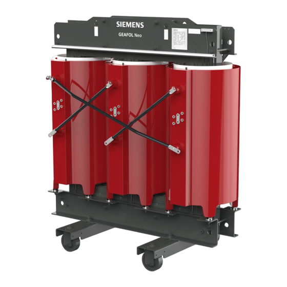
- Page 1 Operating Manual for Siemens Cast-resin Dry Type Distribution Transformer siemens.com.cn...
-
Page 2: Table Of Contents
Catalogue 1. Scope of Application ............... 1 2. Reference Standards ............... 1 3. Safety Guidelines ..............2 4. Product Structure ..............4 5. Transportation, Transfer, Lifting, Handover, Storage ....7 6. Installation ................12 7. Commissioning ................ 18 8. Operation ................21 9. -
Page 3: Scope Of Application
1. Scope of Application This Manual applies to all cast-resin dry-type Cast-resin dry-type transformers are widely used transformers of Siemens with three-phase and single- indoors, especially in fire hazard areas and underground phase, including special purpose transformers such as: flooding areas. Generally, cast-resin transformers can be rectifier transformers and earthing transformers. -
Page 4: Safety Guidelines
After the overhaul, dismantle the grounding wire, evacuate the personnel from the site, and energize the transformer after dismantling the warning sign. If the transformer is damaged or does not work for some unclear reason, please contact Siemens manufacturer. 3.2 Operator safety matters When lifting the transformer vertically, it is strictly forbidden to stand below, and never enter the lifting work area of the crane and the operating radius of the vehicles and machine without permission. - Page 5 Make sure that no operator performs commissioning or other operations on the transformer body before power on. Keep a safe At the moment of power on, the operator shall maintain an effective and safe distance from the transformer. distance When the transformer needs to be reparied d after tripping or power outage, it is strictly prohibited to repair the transformer itself immediately.
-
Page 6: Product Structure
4. Product Structure 4.1 Transformer body Low-voltage terminal Insulator Siemens logo Nameplate Lifting hole Upper clamping Insulating cylinder Safety sign High-voltage tapping High-voltage winding Earth terminal Lower clamping Wheels Towing hole High-voltage connection tube High-voltage terminal Remarks: This picture is a standard legend and does not cover all types of transformers... - Page 7 4.2 Transformer enclosure Enclosure lifting ring Siemens Logo Nameplate Enclosure flank Safety sign Air inlet Door panel Door lock Observation window Position number plate Temperature control system Primary / Secondary side marking Air outlet Foundation Enclosure earth terminal...
- Page 8 Impedance voltage: Impedance voltage, classes also known as short circuit voltage, Type of cooling: represents the voltage loss (percentage) Manufacturer: Siemens Transformer AN -- Natural air cooling on the transformer's impedance when (Guangzhou) Co., Ltd. AF -- forced air cooling...
-
Page 9: Transportation, Transfer, Lifting, Handover, Storage
5. Transportation, Transfer, Lifting, Handover, Storage 5.1 Transportation According to the packaging requirements of the destination and customers (such as moisture-proof or waterproof), the appropriate transport and packaging scheme shall be selected. During the transportation process, the products are firmly placed, and shaking, collision and movement are prohibited. - Page 10 5. Transportation, Transfer, Lifting, Handover, Storage 5.2.2 If the transformer is packed with wooden pallet support, it shall be lifted from the lifting hole of the transformer. Or shall be transferred according to fork-lift marks, as shown below. Wooden pallet support packing and fork-lift transportation Wooden pallet support packing and lifting 5.2.3 If there is only the transformer body (without packaging), it shall be lifted from the lifting hole of the body, as shown in the following figure.
- Page 11 5.3 Lifting 5.3.1 Vertical lifting The unloading and transfer methods of transformers after unpacking shall be as follows: 1. The transformer has no protective enclosure and can only be lifted by slings through the lifting holes of the upper clamping piece. The lifting angle must comply with the requirements on the labels affixed beside the lifting holes, as shown in the following figure.
- Page 12 5. Transportation, Transfer, Lifting, Handover, Storage 5.3.2 Horizontal transfer 1. When the transformer has no protective enclosure and needs to be transferred: a. If the transformer is equipped with rollers (unconventional configuration), the external traction equipment can be fixed through the traction hole of the lower clamping piece of the transformer. Afterwards, pull the transformer horizontally, as shown below.
- Page 13 Open the transformer package and immediately check for damage during transport. In case of damage, please claim compensation against the carrier and ask the representative of Siemens to coordinate this issue if necessary. Report the damage to Siemens through the Siemens representative who is in charge of such matters.
-
Page 14: Installation
6. Installation 6.1 Positioning Before the transformer is positioned, check the product size drawing and foundation drawing, and check whether the actual size of foundation corresponds to the transformer base. Confirm that the foundation is level and able to withstand the weight of the transformer. - Page 15 6.3 Low voltage side busbar or cable connections The low-voltage terminal of the transformer has reserved cable connection holes, and fasteners with loosening preventive measures are required to fix the cable or bus bar. If it is required to be equipped with copper-aluminium composite foil (cupal) as specially specified in the contract, the copper-aluminium composite foil (cupal) shall be installed between the low-voltage terminal of the transformer and the cable, or between the low-voltage terminal of the transformer and the bus bar.
- Page 16 6. Installation 6.4 Cable installation layout 6.4.1 Installation wiring with enclosure: For the transformer with protective enclosure, cables in its high-voltage side and low-voltage side can be imported to internal part of the enclosure through the top or bottom of the enclosure, which can be connected to the corresponding wiring site of the transformer.
- Page 17 6.4.2 Installation wiring without enclosure The high voltage side cable can be connected to the transformer after layout in the bottom cable tray or after layout the top cable tray. Cable or bus bar can used for the low-voltage side connection. If the bus bar connection is used, soft connection transition is recommended to avoid mechanical impact on the low-voltage winding and reduce noise level due to structural reasons.
- Page 18 6. Installation 6.5.3 Connection torque Bolts shall be secured with a torque wrench to ensure uniform clamping force. To eliminate any restoration after fastening at the contact areas, it is recommended that the fastening bolts be re-checked after several weeks. However, the torque shall not be higher than the torque used in the first installation.
- Page 19 Maximum voltage Um ① Rated lightning impulse withstand voltage LI ① Minimum clearance value of the equipment List 1 List 2 (Effective value) ① See IEC 60071 * If there is a high-voltage tap on this side, parameters of column 'a' shall apply to column 'b'; Otherwise, column 'c' applies. 6.7 Grounding After the transformer is installed, ensure that the transformer body and enclosure are reliably grounded.
-
Page 20: Commissioning
7. Commissioning 7.1 Adjustment of transformer accessories 7.1.1 Commissioning of temperature control system The transformer may be equipped with a temperature control system to monitor the temperature of the winding to prevent abnormal temperature rise of the winding, thereby protecting the transformer. The temperature control system includes a temperature controller and a temperature sensor (PT100). - Page 21 7.1.3 Electromagnetic lock The electromagnetic lock (as shown below) is installed on the protective enclosure of the transformer (if electromagnetic lock is required in the contract) to realize the joint defense requirements of the equipment. Electromagnetic locks with different functions can be selected according to user requirements. Refer to the following commissioning steps: a.
- Page 22 7. Commissioning 7.3 Pre-commissioning test 7.3.1 Voltage ratio test: Measure the voltage ratio of the winding under all taps and the connection group. The allowable deviation of rated tap voltage ratio shall not exceed ± 0.5%, except for special transformers. 7.3.2 Wingding resistance test: Measure the DC resistance of the winding at all taps and records the winding temperature.
-
Page 23: Operation
8. Operation 8.1 Voltage regulation. If the actual grid voltage deviates from the rated voltage of the transformer, the tapping gear of the transformer can be adjusted appropriately to control the output voltage value. a. For no-load voltage regulation, the transformer gear tap shall be adjusted to the appropriate gear to keep in line with the grid voltage. - Page 24 Overload curve of SIEMENS GEAFOL® CRT (without cooling fans) Note: Above are the overload curves of the transformer under natural-cooling condition. The design of overload capacity of the transformer is not...
-
Page 25: Maintenance
9. Maintenance Cast-resin transformers are maintenance-free. Routinely inspect and clean the windings, bolt connections, alarm devices and all fan functions once a year. If the transformer is in dusty environment or close to the pollution source, it is recommended to clean the equipment every six months. It is recommended to fully inspect and clean the transformer every 5 years. - Page 26 (85 ~ 250 V) does not display It is internal failure of temperature controller, power interface of Contact Siemens After Sales Service Center to replace temperature controller is energized, but panel indicator lamp is not on with a new temperature controller...
-
Page 27: Appendix
10. Appendix Exploded diagram of cast resin transformer Disassembling diagram of cast resin transformer body Wheels Foundation Lower clamp High-voltage connecting rod Insulating cylinder Upper iron yoke Neutral bar Low-voltage winding High-voltage winding Upper clamp Fixed screw Remarks: The picture is a standard legend and does not cover all types of transformers. - Page 28 10. Appendix Disassembling diagram of cast resin transformer enclosure Low voltage outlet cover Top cover (high-voltage side) assembly Top cover (high-voltage side) assembly Top cover (middle) assembly Crossbeam Crossbeam Cable support (top left and right) (top cover support) assembly assembly Crossbeam (front and rear of top) assembly...
-
Page 29: Warranty Instructions
2. During the warranty period, under the operation conditions as stipulated in the contract, the faults caused by the quality problems of the products shall be repaired free of charge. The warranty period for the products repaired by Siemens shall follow the provisions of original contract. -
Page 30: Customer Satisfaction Questionnaire
We sincerely hope and thank you for that you could give us your comments or suggestions on our company: Customer Signature/Date: Please fill in this page and send it to us by means of scanning or photographing via Email: allen.cao@siemens.com... - Page 32 解西门子配 电设备与系 统信息 If you have any questions about the distribution transformer, please contact us. Siemens Energy Management Customer Service Center Service Hotline: 400 070 5500 Siemens Transformer (Guangzhou) Co., Ltd Contact information of the after-sale service: E-mail: allen.cao@siemens.com hongjian.zheng@siemens.com Tel.:...