Table of Contents
Advertisement
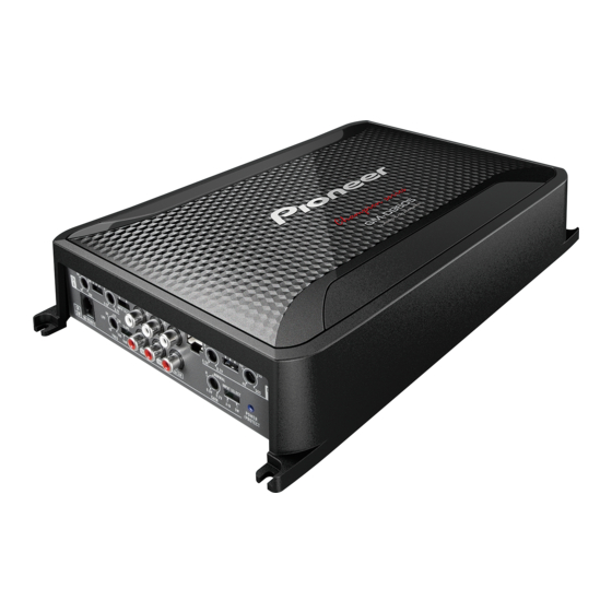
BRIDGEABLE FOUR-CHANNEL POWER AMPLIFIER
GM-D9605
PIONEER CORPORATION
PIONEER ELECTRONICS (USA) INC. P.O. Box 1760, Long Beach, CA 90801-1760, U.S.A.
PIONEER EUROPE NV Haven 1087, Keetberglaan 1, 9120 Melsele, Belgium
PIONEER ELECTRONICS ASIACENTRE PTE. LTD. 253 Alexandra Road, #04-01, Singapore 159936
PIONEER CORPORATION 2015
1-1, Shin-ogura, Saiwai-ku, Kawasaki-shi, Kanagawa 212-0031, Japan
GM-D9605/XEEL
ORDER NO.
CRT5800
/XEEL
K-ZZZ OCT. 2015 Printed in Japan
Advertisement
Table of Contents

Related Manuals for Pioneer GM-D9605


Summary of Contents for Pioneer GM-D9605
- Page 1 PIONEER CORPORATION 1-1, Shin-ogura, Saiwai-ku, Kawasaki-shi, Kanagawa 212-0031, Japan PIONEER ELECTRONICS (USA) INC. P.O. Box 1760, Long Beach, CA 90801-1760, U.S.A. PIONEER EUROPE NV Haven 1087, Keetberglaan 1, 9120 Melsele, Belgium PIONEER ELECTRONICS ASIACENTRE PTE. LTD. 253 Alexandra Road, #04-01, Singapore 159936 PIONEER CORPORATION 2015 K-ZZZ OCT.
-
Page 2: Table Of Contents
10.2 MAIN PCBA (OUTPUT PART) ....................... 17 10.3 MAIN PCBA (SW channel), SUB PCBA ....................18 10.4 MAIN PCBA (POWER PART) ........................ 19 11. PCB CONNECTION DIAGRAM ........................20 11.1 MAIN PCBA ............................20 11.2 SUB PCBA ............................. 22 12. ELECTRICAL PARTS LIST .......................... 23 GM-D9605/XEEL... -
Page 3: Service Precautions
Before disassembling the unit, be sure to turn off the power. Unplugging and plugging the connectors during power-on mode may damage the ICs inside the unit. Please be sure to conduct line process to original status if you make assembling after repair. GM-D9605/XEEL... -
Page 4: Notes On Replacing Parts
704), adjust the position of the part according to the following procedure. Put the Amp Unit on blocks. Put a paper between the block and the Amp Unit, and outline transistors and diodes. Put a part to replace in the outline. GM-D9605/XEEL... -
Page 5: Notes On Adjustment
Be sure to use lead-free solder and a soldering iron that can meet specifications for use with lead-free solders for repairs accompanied by reworking of soldering. 2. SPECIFICATIONS 2.1 SPECIFICATIONS For all items except the backup current, refer to the Owner's Manual. Backup current ......... 1 mA or less GM-D9605/XEEL... -
Page 6: Basic Items For Service
3.2 JIGS LIST - Jigs List Name Jig No. Remarks Bond GYL1006 Applying to choke coil, resistor and capacitor Bond TB1401B or TB1401M For fixing screws (Made by ThreeBond) - Grease List Name Grease No. Remarks Grease GEM1057 Applying to Heatsink GM-D9605/XEEL... -
Page 7: Block Diagram
4. BLOCK DIAGRAM MAIN PCBA DC +/- 15 DC +/- 60V, DC -48V, DC +/ -5V RCA input(AL) Isolator Buffer amp with gain LPF/HPF/Pass Gain volume RCA input(AR) Isolator Buffer amp with gain LPF/HPF/Pass Driver IC (IRS2093M) MOSFET(IRF6775M) of Power AMP of output 2CH or 4CH Speaker... -
Page 8: Diagnosis
5. DIAGNOSIS 5.1 CONNECTOR FUNCTION DESCRIPTION GM-D9605/XEEL... -
Page 9: Operational Flowchart
Failure of IC113 and Q305/306. The signal can't be found on the Speaker terminal side of L401. Failure of IC113 and Q405/406. The signal can't be found on the Speaker terminal side of L501. Failure of IC113 and Q515/518. GM-D9605/XEEL... -
Page 10: Service Mode
MAIN PCBA. Apply the glue (TB1401B or TB1401M) to all screws when you assemble the product. When you replace parts that are applied silicon glue, re-apply silicon glue to the Holder Holder Holder Fig.3 same place after replacing. GM-D9605/XEEL... -
Page 11: Adjustment
Connection Diagram MAIN PCBA GND (Chassis) Multimater Adjustment Method Symptoms due to improper adjustment Adustment item Measurement point Masuring instruments Specs Adjusting point Amplifier output current Between D511 anode Multimater 5.7V SV501 limit value setup and GND (Chassis) GM-D9605/XEEL... -
Page 12: Exploded Views And Parts List
Screw adjacent to mark on the product are used for disassembly. For the applying amount of lubricants or glue, follow the instructions in this manual. (In the case of no amount instructions,apply as you think it appropriate.) 9.1 PACKING GM-D9605/XEEL... - Page 13 Palstic bag of cable 15120100800 ST4*18 screw 16090112010 M3 wrench 16100200250 Palstic bag of manual 15120206610 M1.5 wrench 16100200260 Palstic bag of unit 15120212830 Bubble bag of accessory 15120401000 Owner’s Manual Part No. Language 15090317101 English, Spanish(Espanol), Portuguese(B), Arabic GM-D9605/XEEL...
-
Page 14: Exterior
9.2 EXTERIOR GM-D9605/XEEL... - Page 15 16170108810 Rubber pad 12*7/1.6 16170108910 Remote controller unit 42300315 Knob 13200203600 Volume 14030302200 ST2.6*10 screw 16090101710 Remote cover 22300113 Remote bottom 22300115 *NOTE When you replace sheets #9 & #10, re-apply silicon grease (GEM1057) after wiping off silicon grease. GM-D9605/XEEL...
-
Page 16: Schematic Diagram
SCHEMATIC DIAGRAM Note: When ordering service parts, be sure to refer to " EXPLODED VIEWS AND PARTS LIST" or MAIN PCBA(AL/AR and BL/BR ch PART) "ELECTRICAL PARTS LIST". GAIN : 0dB GAIN : -11.0[6.5V]/12.0dB[Normal]/20.0dB[0.2V] GAIN : 0.0dB (Vi=-31.0dBv) (Vo=-31.0dBv) (Vo=-19.0dBv)[Normal] (Vo=-19.0dBv) GAIN CONTROL LPF/HPF/PASS... -
Page 17: Main Pcba (Output Part)
MAIN PCBA (OUTPUT PART) GAIN 19.0dB (Vo=0.0dBv) POWER AMPLIFIER for A/B ch SPEAKER OUTPUT DC DETECTION... -
Page 18: Main Pcba (Sw Channel), Sub Pcba
SUB PCBA MAIN PCBA (SW channel) GAIN 19.0dB GAIN 19.0dB (Vo=0.0dBv) (Vo=0.0dBv) ISOLATOR MIXING GAIN CONTROL BUFFER BASS BOOST BUFFER LPF/HPF/PASS POWER AMPLIFIER for Sub woofer ch THERMAL PROTECTOR GAIN 0.0dB GAIN 27.0dB (Vo=-270dBv) (Vo=0.0dBv) -
Page 19: Main Pcba (Power Part)
MAIN PCBA (POWER PART) DC/DC CONVERTER ON/OFF +14.4V PROTECTION THERMAL OVER VOLTAGE CONTROL DETECTION DETECTION +60V DC/DC CONVERTER -48V -60V +28V -16V -28V VOLTAGE REGULATOR +15V INDICATOR -15V... -
Page 20: Pcb Connection Diagram
PCB CONNECTION DIAGRAM NOTE FOR PCB DIAGRAMS 1.The parts mounted on this PCB 2.Viewpoint of PCB diagrams include all necessary parts for Capacitor Connector several destination. For further information for respective destinations, be sure SIDE A to check with the schematic dia- gram. - Page 21 SIDE B MAIN PCBA...
-
Page 22: F 11.2 Sub Pcba
11.2 SUB PCBA SUB PCBA SIDE A CN102 SUB PCBA SIDE B GM-D9605/XEEL... -
Page 23: Electrical Parts List
14070200700 Q 516 POWER MOS FET 14070200700 D 705 Diode 14060902500 Q 517 POWER MOS FET 14070200700 D 706 Diode 14060902500 Q 518 POWER MOS FET 14070200700 D 707 Diode 14060902500 D 709 Diode 14060905600 Q 701 Transistor 14070301500 GM-D9605/XEEL... - Page 24 R 255 14021602700 R 113 14021604200 R 256 14021603200 R 114 14021602700 R 257 14021604800 R 115 14021603780 R 258 14021601300 R 116 14021602700 R 265 14021403360 R 117 14021603800 R 266 14021603300 R 118 14021603700 R 267 14021603800 GM-D9605/XEEL...
- Page 25 R 404 14021604415 R 530 14021603800 R 405 14021605500 R 406 14021605500 R 531 14021604420 R 407 14021604415 R 532 14021605200 R 533 14021600900 R 408 14021604415 R 534 14021600900 R 410 14021604210 R 535 14021603800 R 412 14021602400 GM-D9605/XEEL...
- Page 26 R 594 14021440400 R 746 14021232500 R 595 14021440400 R 750 14021440400 R 596 POWER MOX R 14021380200 R 751 14021440400 R 597 14021440885 R 752 14021604300 R 598 14021441300 R 753 14021603800 R 599 14021441300 R 754 14021605600 GM-D9605/XEEL...
- Page 27 C 345 14042300860 C 141 14022100600 C 346 14042300840 C 142 14042300870 C 351 14022100600 C 143 14041604920 C 353 14042201400 C 144 14042300860 C 355 14042201400 C 145 14042300860 C 356 14040700900 C 146 14042300840 C 357 14042000740 GM-D9605/XEEL...
- Page 28 C 550 14041605130 C 551 14041401900 C 775 14042300900 C 776 14042002305 C 552 14041401900 C 553 14041401900 C 777 14042002305 C 554 14041401900 C 779 14042002305 C 780 14042002305 C 555 14022100010 C 556 14042300900 C 782 14042300900 GM-D9605/XEEL...
- Page 29 C 803 14021700100 C 804 14021700100 C 805 14041401900 C 806 14042300840 C 807 14041401900 C 808 14042300840 C 809 14041401900 C 810 14042300840 C 811 14041401900 C 812 14042300840 C 813 14041401900 C 814 14042300840 C 823 14042202000 GM-D9605/XEEL...