Advertisement
Table of Contents
- 1 Table of Contents
- 2 Specifications
- 3 Safety Devices
- 4 Overview of the Washing Machine
- 5 Overview of the Control Panel
- 6 Main Function
- 7 Technical Point
- 8 General Error Function
- 9 Trouble Diagnosis
- 10 Test Mode
- 11 Designation of Main Components
- 12 Pcb Schematic Diagram
- 13 Pcb Circuit Diagram
- 14 Setting up a Wash Machine
- 15 Assemble and Disassemble
- 16 Tools for Disassembly and Assembly
- Download this manual
SERVICE
WASHING MACHINE
WASHING MACHINE
S621GWL2/YLW
S621GWS2/YLW
S621GWS2/YLP
Manual
Caution for the safety during servicing
14
15. EXPLODED VIEW AND PARTS LIST
S821GWG2/YLW
S821GWL2/YLW
S821GWS2/YLW
S821GWS2/YLP
CONTENTS
Advertisement
Table of Contents

Related Manuals for Samsung S621GWL2/YLW


Summary of Contents for Samsung S621GWL2/YLW
-
Page 1: Table Of Contents
WASHING MACHINE S621GWL2/YLW S821GWG2/YLW S621GWS2/YLW S821GWL2/YLW S621GWS2/YLP S821GWS2/YLW S821GWS2/YLP SERVICE Manual WASHING MACHINE CONTENTS Caution for the safety during servicing 1. SPECIFICATIONS 2. SAFETY DEVICES 3. OVERVIEW OF THE WASHING MACHINE 4. OVERVIEW OF THE CONTROL PANEL 5. MAIN FUNCTION 6. - Page 2 Caution for the safety during servicing 1. Do not allow the customer to repair the product. ☞ The person may be injured or the product life may be shortened. 2. Execute A/S after unplugging the power supply unit. ☞ Be care of the electric shock. 3.
-
Page 3: Specifications
1. Specifications FRONT LOADING TYPE WASH TYPE GROSS W 680mm X D 478mm X H 892mm DIMENSION W 598mm X D 340mm X H 844mm 50 kPa ~ 800 kPa WATER PRESSURE GROSS 58 kg WEIGHT 55 kg 3.5 kg (DRY LAUNDRY) WASH and SPIN CAPACITY 220 V 110 W... -
Page 4: Safety Devices
2. Safety Devices ※ We adapt 5 safety devices for users to use this wash machine safely. 1) Balancing device (ASSY-Main PCB) → When the laundry is out of balance, to prevent the noises and vibrations, the unbalance detecting sensor helps the laundry laid even and continue the dehydating process. 2) Anti-over water supply device →... -
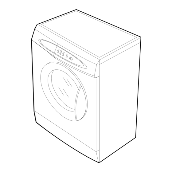
Page 5: Overview Of The Washing Machine
3. Overview of the Washing Machine - 4 -... -
Page 6: Overview Of The Control Panel
4. Overview of the control panel S821 S621 Detergent dispenser Display panel Displays wash cycle and error messages by LED lamps. Course button Press the button repeatedly to select one of the six availabel wash program. {Cotton.Synthetics.Delicates .Quick.Rinse+Spin.Spin.Cotton }. Temperature selection button Press the button repeatedly to cycle through the available water temperature options (cold, 40 ∞... -
Page 7: Main Function
5. Main function 1) Auto power S/W off function ● After power on, the auto power S/W off function automatically switches power off for you if you do not press selection button for 10 minutes ● After selecting the function, the auto power S/W off function automatically switches power off for you if you do not press start/pause button for 10 minutes ●... - Page 8 5. Main function 4) Power-out compensation function ● If power is out on selected process, the process before power out is stored to EEPROM, once power is back the process before power out continues. ● When power is back, washing process starts from the process at the point of the power out, rinse/drain process starts from the initial process.
- Page 9 5. Main function 6) Fuzzy washing function ( weight-sensing) ☞ After finishing initial water supply, when the fall of the water level needs supplementary water supply, Sensing function perceives the weght with the supplementary water supply numbers and starts to work. Under the course of Cotton, if the supplementary water supply numbers become 3 - 4 times the function is going at default condition ( high water level ), if 1-2 below that is going at middle level, if 0 below low water level, heating hours and rinse hours depend on the above data.
- Page 10 5. Main function 8) Unbalance detecting & laundry balance positioning system ① Just before the hydrating process and just after reversal rotation for balancing laundry position, this function is carried out ② The initial 6 sec is the period of reversal rotation for balancing laundry position , Drum rotates 50rpm for initial 6 sec ③...
-
Page 11: Technical Point
6. Technical point 1) Motor on/off time at each course unit:sec Washing Rinse Course Motor r.p.m Cotton Synthetics Delicates Quick 2) Final dehydrating r.p.m at each course unit:rpm Model S821 S621 Course Cotton Synthetics Delicates Quick ※ You can change the r.p.m to the above a table by use spin button under no spin situation. - 10 -... - Page 12 6. Technical point 3) The water level data at each course unit:Khz Water level Supplemetary water Supplemetary water Default water level(khz) Course START(Khz) end(khz) 23.50 24.00 23.70 Washing large 22.45 Cotton middle 22.80 24.00 23.50 Rinse small 23.30 23.50 24.00 23.70 Washing Synthetics...
-
Page 13: General Error Function
7. General Error Function When an error occurs, this function starts to keep generating error melody sounds and displays error indicators as shown in the followings per corresponding error by blinking in 0.5sec interval until the error status is completely cleared out. In this case, all the driving devices are turned off until the error is cleared out. - Page 14 7. General Error Function - If the same signal as the above table is detected for more than 5 seconds, it is a PRESSURE S/W Error. - When the error occurs, water drain pump will operate for 3 min. and then turn off the water drain pump.
-
Page 15: Trouble Diagnosis
8. Trouble Diagnosis - As the micom wash machine is configured of the complicate structure, there might be the service call. Below information is prepared for exact trouble diagnosis and suitable repair guide. Caution for the Repair and Replacement Please follow below instruction for the trouble diagnosis and parts replacement. 1) As some electronic components are damaged by the charged static electricity from the resin part of wash machine or the human body, prepare the human body earth or remove the potential difference of the human body and wash machine by contacting the power supply plug when the work contacting to PCB is... - Page 16 8-1. Trouble Diagnosis Item Cause and treatment - Is the PCB connector connected well? - Is the voltage normal? - Is the power supply plug connected well? - Is the noise filter connected well? The power is not supplied - Is the secondary output of the power supply transformation normal? - Is the fuse disconnected? (option) ï...
- Page 17 8-2 . Problem Checkking And Method Of Pcb 8-2-1 The Part Of Power Source NO Power On The Voltage Of Between ⓐ and ⓑ Is Check The Trans As Big As 12V? The Voltage Of Check The Diode(D15-D19) Between ⓒ and ⓓ Is And Condenser(CE7) As Big As 12V? The Voltage Of...
- Page 18 8-2-2. Reset Part The Value Of Measurement Result Of Check The Power Source Between Micom 23 And Gnd Is 5V? Check IC4 7033 CE4 1UF 8-2-3. Interrupt Part Check The Curve Check D11 - D14 Output Of ⓐ ? Check The Micom Check TR12, R29 Number 31 ? Check The Part Of...
- Page 19 8-2-4. Checking The Part Of An Oscillator When The Micom 18,19 Check, The Value Is Check Resonator 8Mhz? Exchange Micom And Check R53 R53 1M RESO 8MHz - 18 -...
- Page 20 8-2-5. Driving Part Checking ◆ Confirm The Output Of DC5V, When The Every Part Of Micom Number Check, According To The Some Problem Condition ex) When The Drain Is Not Operating But Pump Motor Is Operating, Check The 5Voltage Of Micom Micom Number, 9 Is Micom Bad 5Voltage?
- Page 21 8-2-6. Confirm The Driving Part Of Motor Motor Is Not Spinning Check BD1, TRIAC4 Motor Is Not Turnning Check RELAY2 Right And Left Check The Tacho Part MICOM IC 65003 COIL1 TRIAC4 1W 300 RELAY3 - 20 -...
- Page 22 8-2-7. Checking The Tacho Part Have The Motor Turn In Hand Is The Rectangular Check The Surroundings Curve In The Micom Circuit And TR13 21,10th ? Exchange The Motor MICOM R41 4.7K TR13 R43 1K - 21 -...
-
Page 23: Test Mode
9. Test Mode Bio 60 Softener Power 800rpm 600rpm Cold No Spin Star t/ Rinse+Spin Pause 1. Driving Compartment Test Mode A. Hold down ì 1î and ì 2î keys simultaneously and then press POWER S/W ì 4î on. B. The driving compartment can be tested when you press ì 3î key right after entering into the initial stage of the TEST MODE. -
Page 24: Designation Of Main Components
10. Designation of Main Components 10-1 Normal / Reverse Revolution of Motor and R. P. M. Control 1 2 3 4 5 6 7 8 9 10 Rotor Stator coil Rotor Stator coil STATOR WASHING MOTOR <Figure1> <Figure2> ( ± 7%) STATOR(51) ROTOR(8.9) TACHO(3.4) PROTECTOR(6.7) "H"(mm) Code-No. - Page 25 10-3 Heater 1) Capacity : AC 230V/800W 2) Location : Bottom of TUB 3) Function : Raise the water temperature supplied at the wash process. Thermistor 4) Resistance value : 62.63~69.22 Ω 5) Thermal Fuse : 128∞ C 10-4 Detergent tub and water supply value A Detergent tub is composed of housing and 3 drawers .
- Page 26 10-6 ASSY-TUB BACK INNER-BEARING OUT-BEARING OIL-SEAL (unit : mm) TYPE INNER-BEARING(A) OUT-BEARING(B) OIL-SEAL(C) Assy-Housing Bearing(D) Assy-Tub Back 24.3 DC97-02133A DC97-02103A 10-7 ASSY- DRUM (unit : mm) TYPE CODE-NO. REMARK Lifter type DC97-02099B S821/S621 10-8 ASSY-PUMP DRAIN 1) Capacity : AC 230V 34W 2) Location : Front bottom(R) 3) Resistance : 15 Ω...
-
Page 27: Pcb Schematic Diagram
11. PCB Schematic Diagram - 26 -... -
Page 28: Pcb Circuit Diagram
11-1. PCB CIRCUIT DIAGRAM... - Page 29 11-1. ASSY-PCB Part List Code NO Description Spercificatio Q'ty Remark 0402-001404 DIODE-BRIDGE GSIB1560,600V,15A,SIP-4,ST 0402-000137 DIODE-RECTIFIER 1N4007,1000V,1A,DO-41,TP 0402-000137 DIODE-RECTIFIER 1N4007,1000V,1A,DO-41,TP 0402-000137 DIODE-RECTIFIER 1N4007,1000V,1A,DO-41,TP 0402-000137 DIODE-RECTIFIER 1N4007,1000V,1A,DO-41,TP 0402-000137 DIODE-RECTIFIER 1N4007,1000V,1A,DO-41,TP 0402-000137 DIODE-RECTIFIER 1N4007,1000V,1A,DO-41,TP 1103-001203 IC-EEPROM 524C20D21,128x8Bit,DIP,8P,300MIL,-,2.5V,-, DE13-20016A IC-VOLT REGU KA7805A,TO-220AB,1A,0/125C,-,- 7805 3501-001180 RELAY-MINIATURE 12VDC,400MW,-,2FORMC,7MS,3MS RELAY3...
-
Page 30: Setting Up A Wash Machine
12. Setting up a wash machine. 12-1 Remove the safety device for carriage 1) Remove 3 safety device volts with a enclosed wrench for safety device remove 2) Plug the 3 holes with 3 caps after removing the 3 safety device volts. * Take care of 3 safety device volts and a wrench , you need these when you move wash machine safely. - Page 31 12. Setting up a wash machine. 3) Even though adjustment legs came out all the way, if machine is not levled , prop up the machine with the wood or brick to make it even. (Do not use fragile material or slippery material such as laminated paper) 12-2-2 The condition of setting up sink( Disassembled Ass'y- Cover Top) 1) Spin the adjustment leg to the left and remove them from the front and rear side of the machine.
- Page 32 12. Setting up a wash machine. Door Opening Dimension(Slim Model) 12-3. 760 mm ② Side ① ● (When The Door Vertically Open ) The distance between door and the rear side is 760mm ① ② Upper ② ③ ① 225 mm 255 mm ●...
-
Page 33: Assemble And Disassemble
13. Assemble and Disassemble 1. ASSí Y-COVER TOP 1) Remove two screws fixing the top-cover on back side. 2) Push the top-cover back about 15mm and pull it up. SCREW 3) Ití s possible to exchange and service Assy-Panel (PCB), the pressure-sensor, the noise-filter, the water valve and trans(option). - Page 34 13. Assemble and Disassemble 3. BELT 1) Remove the top-cover. 2) Disassemble and assemble the belt. 3) Check the belt is located at center of the motor-pulley. <When assemble the belt> Hook the belt on the motor pulley 1) and place it PULLEY around the pulley 2).
-
Page 35: Tools For Disassembly And Assembly
14. Tools for Disassembly and Assembly TOOL 10mm Heater (1) 13mm Motor (1), Balance (5) ¿ Box driver 17mm 2 holes of each left and right of the shock absorber 19mm 1 Pulley hole Replaceable for the box driver. Double-ended ¡... - Page 36 15. TOP(FRONT) - Exploded View WDA04 J014 Y001 WAA13 C008 WAA12 WDA02 P003 WAA28 C021 J006 WDA06 WDA05 G007 V002 WDA03 P002 WDA01 V001 WDA13 V009 WDA16 V003 WDA25 WDA33 V016 - 35 -...
- Page 37 15. Parts List - TOP(FRONT) LOCATION NO. CODE NO. DESCRIPTION SPECIFICATION Q'TY REMARK C008 DC64-00428A PANEL-CONTROL SB-PJT,HIPS,-,-,-,-,SNOW/W C021 DC64-00429F INLAY-PANEL SS-PJT,PC,T0.5,-,-,LILAC,ENG(S621GWL) S621GWL2/YLW C021 DC64-00429H INLAY-PANEL SS-PJT,PC,T0.5,-,-,IMPERIAL-SILVER, S621GWS2/YLW C021 DC64-00429E INLAY-PANEL SS-PJT,PC,T0.5,-,-,SILVER,RUSSIAN S621GWS2/YLP C021 DC64-00429D INLAY-PANEL SS-PJT,PC,T0.5,-,-,GRN,ENG(S821GWG) S821GWG2/YLW C021 DC64-00429J INLAY-PANEL SS-PJT,PC,T0.5,-,-,LILAC,ENG(S821GWL/...
- Page 38 15. TUB - Exploded View R025 WDB46 R008 WDB12 R014 WDB31 WDB35 WDB10 R020 WDB38 R015 WDB32 R018 WDB34 R016 WDB33 R007 WDB06 WDB46 R026 WDB02 R003 R028 WDB37 WDB26 R013 WDB08 V007 R021 WDB39 R005 WDB03 R024 WDB42 WDB40 R010 WDB17 WDB41...
- Page 39 15. Parts List - TUB LOCATION NO. CODE NO. DESCRIPTION SPECIFICATION Q'TY REMARK R003 DC91-12077A ASSY-CLAMP DIAPHGRAM SWF-P12,TUB R005 DC97-02099B ASSY-DRUM SB-PJT,DRUM-F/B(0.4T) R006 DC47-00006D HEATER KAWAI,SS-PJT,SUS316L,-,-,230V,-,- R007 DC97-02137B ASSY-TUB BACK SB-PJT,SAMBAK(10%) R008 6602-001073 BELT-TIMING GEAR POLYURETHAN,1270,J3,MEG R010 DC61-00856A BRACKET-HEATER SB-PJT,STS430,-,-,-,-,- R013 DC61-20219A DOOR-DIAPHRAGM...
- Page 40 15. CASE - Exploded View J001 WDC01 C007 WAA11 G008 T024 WAC10 WAB15 J012 WDC33 J008 WDC19 R030 C009 WDC06 WAA46 J012 WDC33 WAA37 C023 R017 WDC25 G003 WAC07 V010 WDC17 WDC21 P001 WDC03 R012 WDC14 R012 WDC14 B006 WAC08 WDC12 G020 G025...
- Page 41 15. Parts List - CASE LOCATION NO. CODE NO. DESCRIPTION SPECIFICATION Q'TY REMARK B006 DC97-02079C ASSY-LEG SB-PJT,SLIM/25MM/CHINA C007 DC96-00521B ASSY-M.WIRE HARNESS S621,ROLD-DOOR C009 DC62-30314A VALVE-WATER SWF-P12,NYLON#6,-,-,-,EATON( C023 DC32-30006P SENSOR PRESSURE DN-S14(P1291),TERMINAL-T G003 DC97-00139E ASSY-HOSE DRAIN(O) SB-PJT,PP/L1770/CHINA G008 DC96-00541A ASSY-POWER CORD S621,0.75MM(UCP2) G009 DC96-00149A...
- Page 42 15. Screw/Bolt List CODE NO. DESCRIPTION SPECIFICATION Q'ty ASSEMBLY LOCATION 6011-001421 BOLT-FLANGE M7,L61(29.4),ZPC(YEL),SWRCH18A 6011-001421 BOLT-FLANGE M7,L61(29.4),ZPC(YEL),SWRCH18A WEIGHT/L DC60-40144A BOLT-HEX M10,L41,ZPC2(YEL),SM10C/DAMPER DAMPER+FRAME 6011-001452 BOLT-HEX M10,L20,ZPC(YEL),SWCH10AK,ASSY(WS) PULLEY DC60-40141A BOLT-HEX SM10C/DAMPER,HEX,M8,L66,-,ZPC2(YEL),-,- DAMPER+TUB DC60-40005A BOLT-HEX M4,L60,ZPC2(YEL),SS41C,-,-,-,- DC60-50010A NUT-DIAPHRAGM EGI,M4,-,-,2.5TX20X8 DC60-50010B NUT-DIAPHRAGM EGI,M4.2,-,-,2.5TX20X8 DD60-50018A NUT-FLANGE -,M5XP0.8,FZY,MSWR10,- HINGE 6001-001773...
- Page 43 ELECTRONICS ©Samsung Electronics Co., Ltd. April 2003 Printed in Korea Code No. : DC68 - 01833A...