Cisco UCS E Series Hardware Installation Manual
Servers and network compute engine
Hide thumbs
Also See for UCS E Series:
- Product overview (8 pages) ,
- Installation manual (46 pages) ,
- Troubleshooting manual (28 pages)
Advertisement
Quick Links
Cisco UCS E-Series Servers and the Cisco UCS
E-Series Network Compute Engine Hardware
Installation Guide
Introduction
This document provides installation information for the Cisco UCS E-Series Servers (E-Series Servers) and
the Cisco UCS E-Series Network Compute Engine (NCE). It includes the following sections:
New and Changed Information
Table 1: New and Changed Information for Software Release 3.2.1
Feature
Description
Double-Wide E-Series
Support added to install the
Server refresh
UCS-E1120D-M3/K9 and
UCS-E180D-M3/K9 into the Cisco ISR
4000 series.
Table 2: New and Changed Information for Software Release 3.1.1
Feature
Description
Single-Wide E-Series
Support added to install the
Server refresh
UCS-E160S-M3/K9 into the
Cisco ISR 4000 series.
Table 3: New and Changed Information for Software Release 3.0.1
Feature
NIM E-Series Network
Compute Engine
Cisco UCS E-Series Servers and the Cisco UCS E-Series Network Compute Engine Hardware Installation Guide
Description
Support added to install the NIM E-Series
Network Compute Engine (NIM E-Series
NCE) into the Cisco ISR 4000 series.
Changed in Software
Release
3.2.1
Changed in Software
Updated Sections
Release
3.1.1
"Hardware Requirements"
"Hardware Information for the M3 E-Series
Servers"
"Single-Wide E-Series Servers and the SM
E-Series NCE—Front Panel and Components"
Changed in Software
Release
3.0.1
Updated Sections
"Hardware Requirements"
"Hardware Information for the M3
E-Series Servers"
Updated Sections
"Hardware Information for the NIM
E-Series NCE"
"NIM E-Series NCE"
1
Advertisement

Related Manuals for Cisco UCS E Series


Summary of Contents for Cisco UCS E Series
- Page 1 3.0.1 “Hardware Information for the NIM Compute Engine Network Compute Engine (NIM E-Series E-Series NCE” NCE) into the Cisco ISR 4000 series. “NIM E-Series NCE” Cisco UCS E-Series Servers and the Cisco UCS E-Series Network Compute Engine Hardware Installation Guide...
- Page 2 “Hardware Requirements” Verifying E-Series Server Command to verify that the router 1.0(2) “Verifying E-Series Server or SM Installation recognizes the E-Series Server. E-Series NCE Installation” Cisco UCS E-Series Servers and the Cisco UCS E-Series Network Compute Engine Hardware Installation Guide...
- Page 3 (NCE) are a family of size-, weight-, and power-efficient blade servers that are housed within the Generation 2 Cisco Integrated Services Routers (Cisco ISR G2) and the Cisco ISR 4000 series. These servers provide a general-purpose compute platform for branch-office applications deployed either as bare-metal on operating systems, such as Microsoft Windows or Linux, or as virtual machines on hypervisors, such as VMware vSphere Hypervisor, Microsoft Hyper-V, or Citrix XenServer.
-
Page 4: Hardware Requirements
• M3 E-Series servers can be installed in the Cisco ISR 4000 series only. • The Cisco ISR 4331 has one SM slot. The Cisco ISR 4321 and the Cisco ISR 4431 have no SM slots. • Citrix XenServer is supported on the E-Series Servers only. - Page 5 2911, 2921, 2951, 3925, 3925e, 2921, 2951, 3925, 3925e, 3945, 2921, 2951, 3925, 3925e, 3945, 3945, 3945e, 4331, 4351, 3945e, 4351, 4451-X 3945e, 4351, 4451-X 4451-X Cisco UCS E-Series Servers and the Cisco UCS E-Series Network Compute Engine Hardware Installation Guide...
- Page 6 Table 9: M2 E-Series Servers and NCE Hardware at a Glance Feature UCS-EN120S-M2 SM E-Series UCS-E140S M2 Single-Wide E-Series UCS-E160D-M2 and Server UCS-E180D-M2Double-Wide E-Series Servers Form Factor Single-wide SM Single-wide SM Double-wide SM Cisco UCS E-Series Servers and the Cisco UCS E-Series Network Compute Engine Hardware Installation Guide...
- Page 7 2911, 2921, 2951, 3925, 3925e, 2911, 2921, 2951, 3925, 3925e, 3945, 2921, 2951, 3925, 3925e, 3945, 3945e, 3945, 3945e, 4331, 4351, 4451-X 3945e, 4331, 4351, 4451-X 4351, 4451-X Cisco UCS E-Series Servers and the Cisco UCS E-Series Network Compute Engine Hardware Installation Guide...
- Page 8 This replaces the SD card functionality that was used on M2.The eMMC storage is used for hosting CIMC and is also available as a USB device to the x86 host side. On Cisco UCS-E160S-M3 server, the size of the CIMC partition is 8 GB, and the size of the host partition is 8 GB.
- Page 9 All hardware drives within the E-Series Server must be installed with the same type of storage device: either all SAS drives or all SATA drives. Cisco UCS E-Series Servers and the Cisco UCS E-Series Network Compute Engine Hardware Installation Guide...
- Page 10 2911 ISR G2—2 NCEs 2921 ISR G2—2 NCEs 2951 ISR G2—2 NCEs 3925 ISR G2—2 NCEs 3925e ISR G2—1 NCE 3945 ISR G2—2 NCEs 3945e ISR G2—1 NCE Cisco UCS E-Series Servers and the Cisco UCS E-Series Network Compute Engine Hardware Installation Guide...
- Page 11 The following table shows the Cisco EtherSwitch Enhanced High-Speed WAN Interface Cards (EHWICs) and Cisco EtherSwitch Service Modules that are supported on the E-Series Server. Cisco UCS E-Series Servers and the Cisco UCS E-Series Network Compute Engine Hardware Installation Guide...
-
Page 12: Supported Transceivers
• Do not wear loose clothing around the router. Fasten your tie or scarf and roll up your sleeves to prevent clothing from being caught in the chassis. • Wear safety glasses when working under any conditions that might be hazardous to your eyes. Cisco UCS E-Series Servers and the Cisco UCS E-Series Network Compute Engine Hardware Installation Guide... - Page 13 Electrostatic discharge can damage equipment and impair electrical circuitry. Electrostatic discharge occurs when electronic printed circuit cards, such as those used in Cisco service modules and network modules, are improperly handled and can result in complete or intermittent equipment failure. Always observe the following...
- Page 14 • Follow installation and maintenance procedures as documented by Cisco Systems, Inc. Safety Warnings The following safety warning statements apply to all hardware procedures involving E-Series Servers and NCEs. Translations of these warnings are available in the Cisco Network Modules and Interface Cards Regulatory Compliance and Safety Information document at: http://www.cisco.com/en/US/docs/routers/access/interfaces/rcsi/IOHrcsi.html Danger IMPORTANT SAFETY INSTRUCTIONSThis warning symbol means danger.
- Page 15 To report a gas leak, do not use a telephone in the vicinity of the leak. Statement 1039 Danger Class 1 laser product. Statement 1008 Cisco UCS E-Series Servers and the Cisco UCS E-Series Network Compute Engine Hardware Installation Guide...
-
Page 16: Types Of E-Series Servers And Nces
1) before unplugging the main power connector or 2) while the housing is open, or both. Statement 1043 Types of E-Series Servers and NCEs The following E-Series Servers are available: • Single-wide E-Series Servers • Double-wide E-Series Servers Cisco UCS E-Series Servers and the Cisco UCS E-Series Network Compute Engine Hardware Installation Guide... -
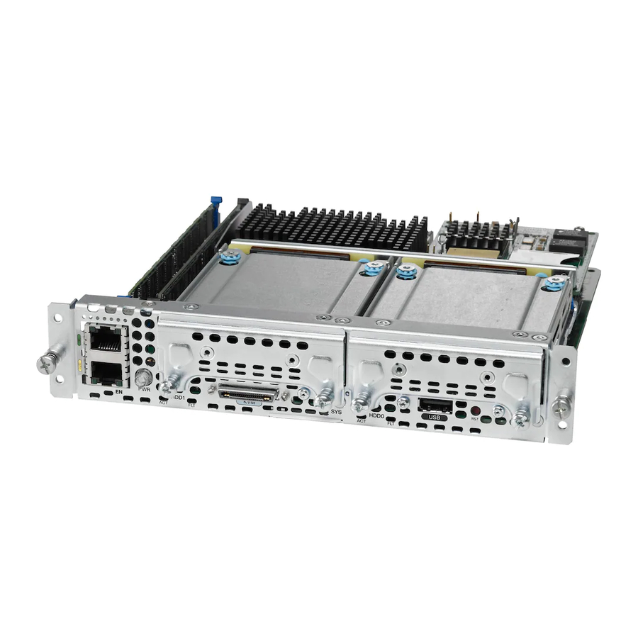
Page 17: E-Series Servers
Reset switch The following figure shows the front panel of the single-wide E-Series Server UCS-E160S-M3. Figure 2: Front Panel of the Single-Wide E-Series Server UCS-E160S-M3 Cisco UCS E-Series Servers and the Cisco UCS E-Series Network Compute Engine Hardware Installation Guide... - Page 18 The following figure shows the KVM connector. Figure 3: KVM Connector USB connector DB15 connector—video port DB9 connector—serial port The following figure shows the internal components of the single-wide E-Series Server. Cisco UCS E-Series Servers and the Cisco UCS E-Series Network Compute Engine Hardware Installation Guide...
- Page 19 Green Status of the hard drive activity: • Steady—Hard drive is present. • Blinking—Active. • Off—Inactive or there is no power supplied to the CPU. Cisco UCS E-Series Servers and the Cisco UCS E-Series Network Compute Engine Hardware Installation Guide...
- Page 20 • 2 Blinks—100 Mb/s speed. • 3 Blinks—1 Gb/s speed. Green Right LED shows whether the link is established: • Steady—Link is established. • Off—No link is established. Cisco UCS E-Series Servers and the Cisco UCS E-Series Network Compute Engine Hardware Installation Guide...
- Page 21 (Optional) HDD2, PCIe assembly or blank slot Each port provides up to 500 mA of current. Devices that require higher power, such as CD/DVD ROM, need their own external power. Cisco UCS E-Series Servers and the Cisco UCS E-Series Network Compute Engine Hardware Installation Guide...
- Page 22 USB port 1 HDD1) Each port provides up to 500 mA of current. Devices that require higher power, such as CD/DVD ROM, need their own external power. Cisco UCS E-Series Servers and the Cisco UCS E-Series Network Compute Engine Hardware Installation Guide...
- Page 23 Table 16: Double-Wide E-Series Server LEDs Color State No memory is installed in this socket. Green Memory M0 is installed. Amber Memory M0 is installed, but fault is detected. Cisco UCS E-Series Servers and the Cisco UCS E-Series Network Compute Engine Hardware Installation Guide...
- Page 24 Blinks when the processor is active. Green Operation is normal. Amber Fault is detected on the processor. Green Blinks when the CIMC is operating normally. Cisco UCS E-Series Servers and the Cisco UCS E-Series Network Compute Engine Hardware Installation Guide...
- Page 25 • Number-1 Phillips screwdriver or a small flat-blade screwdriver • ESD-preventive wrist strap • Tape to secure DC circuit breaker handle—Applicable for routers that use DC power Cisco UCS E-Series Servers and the Cisco UCS E-Series Network Compute Engine Hardware Installation Guide...
- Page 26 Preparing the Router’s SM Slot for E-Series Server or SM E-Series NCE Installation Several Cisco routers have flexible SM slots to support various Cisco server modules. Before installing the E-Series Server or SM E-Series NCE into the router, prepare the router’s SM slot for the server’s particular form factor.
- Page 27 Remove any installed modules, blank faceplates, and slot adapters from the router slot that you want to use. Step 2 Insert the top rails of the slot divider between the two guide rails in the top of the module slot. Cisco UCS E-Series Servers and the Cisco UCS E-Series Network Compute Engine Hardware Installation Guide...
- Page 28 Before You Begin Make sure that you connect the wrist-strap clip to an unpainted portion of the chassis frame to channel unwanted ESD voltages to ground. Cisco UCS E-Series Servers and the Cisco UCS E-Series Network Compute Engine Hardware Installation Guide...
- Page 29 1. Removed the blank faceplates from the slots that you intend to use. See the “Removing the Blank Faceplate from the Router’s SM Slot”. 2. Saved the blank faceplates for future use. Cisco UCS E-Series Servers and the Cisco UCS E-Series Network Compute Engine Hardware Installation Guide...
- Page 30 For the Cisco 3900 ISR G2—If you are using PoE, and you want to install one double-wide E-Series Server and any number of server modules in a Cisco 3900 ISR G2, you must use a second AC and PoE supply to support this configuration.
- Page 31 What to do next What to Do Next 1. Load a compatible Cisco IOS image. See the “Cisco ISR G2, E-Series Server, NCE, and Cisco IOS Software Release Compatibility” section in the Release Notes for Cisco UCS E-Series Servers and the Cisco UCS E-Series Network Compute Engine, Release 3.x.
- Page 32 0/0 ISR4400-4X1GE ok 1d01h 1 ISR4451/K9 ok 1d01h 1/0 UCS-E160DP-M1/K9 ok 1d01h 2 ISR4451/K9 ok 1d01h R0 ISR4451/K9 ok, active 1d01h F0 ISR4451/K9 ok, active 1d01h Cisco UCS E-Series Servers and the Cisco UCS E-Series Network Compute Engine Hardware Installation Guide...
- Page 33 Migrating the E-Series Server from a Cisco ISR G2 into a Cisco ISR 4000 Series If you are migrating the E-Series Server from a Cisco ISR G2 into a Cisco ISR 4000 series, you must first upgrade the CIMC and the BIOS firmware image to the latest version—while the E-Series Server is still installed in the Cisco ISR G2—and then migrate it into the Cisco ISR 4000 series.
- Page 34 Online insertion and removal (OIR) provides uninterrupted network operation, maintains routing information, and ensures session preservation on the Cisco 3900 series ISR G2 and the Cisco ISR 4000 series. You can use online insertion and removal to install or replace hardware without affecting system operations.
- Page 35 E-Series Server from the Cisco 2900 ISR G2. The OIR commands for the Cisco 3900 series ISR G2 and the Cisco ISR 4000 series are different. See the following topics for more information:...
- Page 36 Inserting the E-Series Server in a Cisco 3900 Series ISR G2 The Cisco 3900 ISR G2 that is up and running can detect when an E-Series Server is inserted in the SM slot and will automatically provide power to the server.
- Page 37 Inserting the E-Series Server in a Cisco ISR 4000 Series A Cisco ISR 4000 series that is up and running can detect when an E-Series Server is inserted in the SM slot. After the router detects the E-Series Server, the router software enables power to the server.
- Page 38 M3 servers. Procedure Step 1 Turn off power to the router. Alternatively, the Cisco 3900 ISR G2 and the Cisco ISR 4000 series support OIR. See the “Online Note Insertion and Removal—E-Series Servers” section. Step 2 Using either a number-1 Phillips screwdriver or a small flat-blade screwdriver, unscrew the captive screws on the faceplate and remove the cover faceplate.
- Page 39 (Optional) If the slot is empty, use the screwdriver to loosen the screws on the bracket, and then remove the bracket (see the following figure). Cisco UCS E-Series Servers and the Cisco UCS E-Series Network Compute Engine Hardware Installation Guide...
- Page 40 You cannot replace the memory DIMM in an EHWIC E-Series NCE. If you encounter a problem with the memory DIMM, you must replace the entire EHWIC E-Series NCE. Cisco UCS E-Series Servers and the Cisco UCS E-Series Network Compute Engine Hardware Installation Guide...
- Page 41 The following figure shows the location of the memory DIMMs in a single-wide E-Series Server. Note The single-wide E-Series Servers support up to 16 GB of DDR3 memory DIMMs. Cisco UCS E-Series Servers and the Cisco UCS E-Series Network Compute Engine Hardware Installation Guide...
- Page 42 The following figure shows the location of the memory DIMMs in a double-wide E-Series Server. Note The double-wide E-Series Servers support up to 48 GB of DDR3 memory DIMMs. Cisco UCS E-Series Servers and the Cisco UCS E-Series Network Compute Engine Hardware Installation Guide...
- Page 43 Figure 17: Memory DIMM Location in a Double-Wide E-Series Server The following figure shows the location of the memory DIMMs in the double-wide E-Series Servers UCS-E180D-M3 and UCS-E1120D-M3. Cisco UCS E-Series Servers and the Cisco UCS E-Series Network Compute Engine Hardware Installation Guide...
- Page 44 Procedure Step 1 Turn off power to the router. Note Alternatively, the Cisco 3900 ISR G2 and the Cisco ISR 4000 series support OIR. See the Online Insertion and Removal—E-Series Servers, on page Step 2 Locate the DIMM on the E-Series Server. See the...
- Page 45 Before You Begin Make sure that you connect the wrist-strap clip to an unpainted portion of the chassis frame to channel unwanted ESD voltages to ground. Procedure Cisco UCS E-Series Servers and the Cisco UCS E-Series Network Compute Engine Hardware Installation Guide...
- Page 46 Procedure Step 1 Turn off power to the router. Note Alternatively, the Cisco 3900 ISR G2 and the Cisco ISR 4000 series support OIR. See the Online Insertion and Removal—E-Series Servers, on page Step 2 Locate the DIMM connector. See the...
- Page 47 Figure 22: Front Panel of the EHWIC E-Series NCE LED for power LED for the system Console port VGA port Gigabit Ethernet port (GE2) Figure 23: Internal Components of the EHWIC E-Series NCE Cisco UCS E-Series Servers and the Cisco UCS E-Series Network Compute Engine Hardware Installation Guide...
- Page 48 Purpose Step 1 Action Step 2 Reference Topic Step 3 Gather the required tools and equipment. Tools and Equipment Required for Installation, on page 25 Cisco UCS E-Series Servers and the Cisco UCS E-Series Network Compute Engine Hardware Installation Guide...
- Page 49 Removing Slot Dividers from EHWIC Slots , on page Removing Slot Dividers from EHWIC Slots Slot dividers are removed to permit use of double-wide EHWIC E-Series NCE in the router slots. Cisco UCS E-Series Servers and the Cisco UCS E-Series Network Compute Engine Hardware Installation Guide...
- Page 50 The EHWIC E-Series NCE can be installed either before or after mounting the router, whichever is convenient. Danger Only trained and qualified personnel should be allowed to install, replace, or service this equipment. Statement 1030 Cisco UCS E-Series Servers and the Cisco UCS E-Series Network Compute Engine Hardware Installation Guide...
- Page 51 Align the EHWIC E-Series NCE with the guides in the chassis walls or slot divider, and slide it gently into the slot. (See Figure 25: Installing the Double-Wide EHWIC E-Series NCE in a Cisco ISR G2, on page 52.) Cisco UCS E-Series Servers and the Cisco UCS E-Series Network Compute Engine Hardware Installation Guide...
- Page 52 2. Connect the EHWIC E-Series NCE to the network and then power up the router and the NCE. 3. Verify that the router recognizes the EHWIC E-Series NCE. See the Verifying EHWIC E-Series NCE Installation, on page Cisco UCS E-Series Servers and the Cisco UCS E-Series Network Compute Engine Hardware Installation Guide...
- Page 53 1. Install the EHWIC E-Series NCE into the router. 2. Load a compatible Cisco IOS image. See the “Cisco ISR G2, E-Series Server, NCE, and Cisco IOS Software Release Compatibility” section in the Release Notes for Cisco UCS E-Series Servers and the Cisco UCS E-Series Network Compute Engine, Release 3.x.
- Page 54 KVM port used for keyboard, video, and mouse (KVM) connector. Refer Figure 27: KVM Connector, on page GE Port LED for the SSD drive LED for the CIMC The following figure shows the KVM connector. Cisco UCS E-Series Servers and the Cisco UCS E-Series Network Compute Engine Hardware Installation Guide...
- Page 55 USB connector DB9 connector—serial port The following figure shows the internal components of the NIM E-Series NCE. Figure 28: Internal Components of the NIM E-Series NCE Cisco UCS E-Series Servers and the Cisco UCS E-Series Network Compute Engine Hardware Installation Guide...
- Page 56 • Off—No link is established. Basic Workflow for Installing the NIM E-Series NCE in the NIM Slot Procedure Command or Action Purpose Step 1 Action Step 2 Reference Topic Cisco UCS E-Series Servers and the Cisco UCS E-Series Network Compute Engine Hardware Installation Guide...
- Page 57 2. Save the blank faceplates for future use. 3. Connect a wrist-strap clip to an unpainted portion of the chassis frame to channel unwanted ESD voltages to ground. Procedure Cisco UCS E-Series Servers and the Cisco UCS E-Series Network Compute Engine Hardware Installation Guide...
- Page 58 Align the NIM E-Series NCE with the guides in the chassis walls or slot divider, and slide it gently into the NIM slot. (See Figure 29: Installing the NIM E-Series NCE in a Cisco ISR 4000 Series, on page 58.)
- Page 59 Verifying NIM E-Series NCE Installation 1. Load a compatible Cisco IOS image. See the “Cisco ISR 4000, E-Series Server, NCE, CIMC and Cisco IOS Software Release Compatibility” section in the Release Notes for Cisco UCS E-Series Servers and the Cisco UCS E-Series Network Compute Engine, Release 3.x.
-
Page 60: Removing The Coa
Inserting the NIM E-Series NCE in a Cisco ISR 4000 Series A Cisco ISR 4000 series that is up and running can detect when an NIM E-Series NCE is inserted in the NIM slot. After the router detects the NIM E-Series NCE, the router software enables power to the server. -
Page 61: Cisco Integrated Management Controller
CIMC is the management service for the E-Series Servers. You can use a web-based GUI or SSH-based CLI to access, configure, administer, and monitor the server. For more information on CIMC, see the GUI Configuration Guide for Cisco UCS E-Series Server and the Cisco UCS E-Series Network Compute Engine. Related Documentation... - Page 62 • Open Source Used in Cisco UCS E-Series Servers • Documentation Guides for Third Party Plug-in Tools • For information about installing and connecting the Cisco 2900 series and Cisco 3900 ISRs, see the Cisco 3900 Series and Cisco 2900 Series Hardware Installation Guide •...