Advertisement
Quick Links
Advertisement

Related Manuals for ABB VBF Series


Summary of Contents for ABB VBF Series
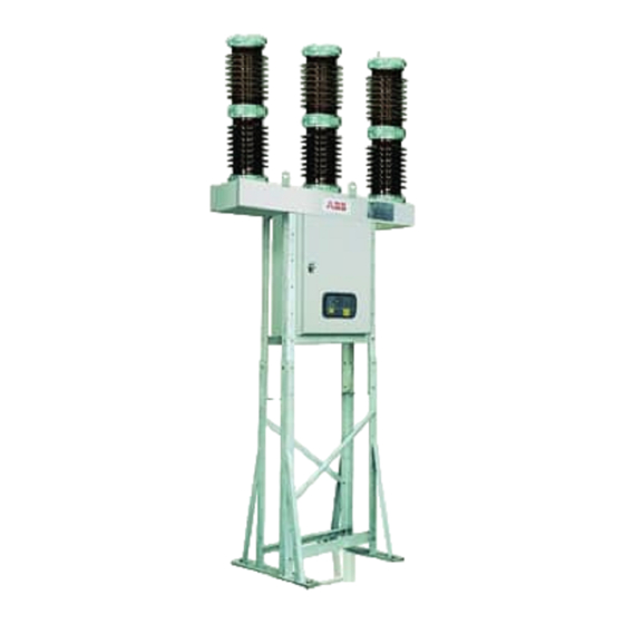
- Page 1 Outdoor Vacuum Circuit Breaker Type VBF Instruction for Installation, Service and Maintenance...
- Page 2 INDEX Sr. No. Title Page No. Product description PART A Receipt, Storage & Safety Packing information, Goods marking and transport Receipt & Storage prior to Installation Safety provisions and assembly instructions PART B Instructions for Installation, Operation & Maintenance General Breaker details Function Installation...
- Page 3 Product description Description Medium Voltage circuit-breaker type VBF, with operating mechanism type ESH. 1.1 Design of the circuit-breaker 1. Pole assembly The circuit-breaker is made up of three separate poles. Pole assembly consists of three poles and a These consist of three main parts. common duct.
- Page 4 Product description 2. Cabinet with operating mechanism 2.1 Base Cabinet The base cabinet is made of painted mild steel. The cabinet houses a spring operated mechanism which is mechanically linked to all three poles. The cabinet also includes the followings: Anti-condensation heater Circuit breaker status indicator Mechanical operation counter...
- Page 5 PART A Receipt, Storage & Safety 1.0 Packing Information, Goods marking & Transport 1.1 Goods marking 1.2 Documents 1.3 Transport 1.4 Lifting Receipt & storage prior to installation 2.1 General 2.2 Receipt & storage of breaker 3.0 Safety provisions and assembly instructions 3.1 Warning texts 3.2 Safety Precaution...
- Page 6 PART A Receipt, Storage & Safety 1.0 Packing Information, goods marking & Each case is marked with case markings on two sides with indelible black ink. The case markings include transport information of case number, gross weight, etc. 1.1 Goods marking In addition to the above, the cases are marked with The circuit-breaker is transported in seaworthy packing the following symbols.
- Page 7 PART A Receipt, Storage & Safety 1.3 Transport Ensure that packing cases are not placed on wet surfaces / waterlogged areas. The circuit- breakers shall be transported in packed condition only. Following precautions are to be Breakers should not be stacked one over the taken while transporting: other.
- Page 8 Each delivery, on receipt, should be checked for: Shortages discrepancies. (Check against order and delivery documents). Any transit damage and material losses. Abnormality, if any, must be notified immediately to: ABB, forwarding agents and the insurance company.
- Page 9 PART A Receipt, Storage & Safety 3.0 Safety provisions for circuit-breaker The entire assembly instruction should be read carefully before starting the assembly work. 3.1 Warning texts Warning texts are stated in 5 different degrees of urgency, which should be carefully observed. These are described below: DANGER indicates an immediate risk situation that can lead to death or serious personal injury if not avoided.
- Page 10 PART A Receipt, Storage & Safety 3.2 Safety Precaution When working on high-voltage circuit breaker the below-mentioned risk must be taken into consideration and corresponding safety measures taken. RISK SAFETY MESAURES 1) Work next to high voltage Warning plate is placed inside the door of the operating device.
- Page 11 PART B Installation, Operation & Maintenance General 1.0 Technical details 5.0 Commissioning 1.1 Type designation 5.1 General procedure 1.2 Specifications 5.2 Space heaters 1.3 Rating plate 5.3 Starting conditions 5.4 Function test 2.0 Breaker details 5.5 Trial switching operations 5.6 Anti-pumping device 3.0 Function 5.7 Check of heaters 3.1 Switching operations...
- Page 12 PART B Installation, Operation & Maintenance General 1.0 Technical details This operating instruction is applicable for Outdoor circuit Breaker type VBF. 1.1 Type designation Outdoor Vacuum Circuit Breaker Type VBF Rated voltage – 24 for 24kV 36 for 36kV Rated normal current - 12 for 1250 Amp 16 for 1600 Amp Rated breaking capacity –...
- Page 13 The rotation of 3.1 Switching operations the common shaft moves the moving contact of As supplied from ABB the circuit breaker will be all the poles upward through the operating stud, open position and closing spring in closing the circuit breaker.
- Page 14 Circuit Breaker can be transported in three parts as explained below. Report any faults immediately to the ABB 1 Cabinet with Spring-Mechanism Drive & representative. Electrical wiring & apparatus. 2 Duct-with-Poles and the inter-pole-links.
- Page 15 PART B Installation, Operation & Maintenance 4.2.1.3. Assembly sequences for Structure : Fix the Lower Leg Assembly as shown. Fix M20 Plain Washer, Spring Washer & Hex nut or Expansion Bolts in case the foundation is with Expansion bolts. Keep Nuts slightly loose for flexibility during entire Assembly of structure.
- Page 16 PART B Installation, Operation & Maintenance Slide Upper Leg (7) in Lower Leg assembly & assemble using M12 bolts, spring, washers, plain washers & Hex Nuts. Fix Support-Angles(9) on Upper Leg Assembly(1) & (7) as Shown Fix Cross-Angles (11) Fix CT Frame(10) on the Support Angles(9) For the sake of flexibility, do not fully tighten the fasteners.
- Page 17 PART B Installation, Operation & Maintenance 4.2.1.4.2 Unpacking of Duct & Pole Assembly Remove top & all side covers of casing containing Poles-with-Duct assembly. Remove Vacuum sealing. Hold Poles-with-Duct Assembly by lifting crane as as shown. Remove the M8 Bolts from the rear covers of the Duct &...
- Page 18 PART B Installation, Operation & Maintenance 4.2.1.6 Assembly of entire Circuit-Breaker on structure Refer figure below before going for assembly. Slowly lower the Circuit-Breaker in such a way that the Cabinet enters inside the Upper Leg Assemblies & rests on the support angles & the Duct rests on the Upper Leg Assemblies of structure.
- Page 19 PART B Installation, Operation & Maintenance These figures are of Y-pole Connection of Driving-Link with composite-lever: Sequence - 1 Sequence - 2 Rotate the Composite-Lever such that the Remove the pin and U-Clip from the hole of the lever-arm matches with the hole in lever arm Driving Link &...
- Page 20 PART B Installation, Operation & Maintenance 4.2.2 Installation of Breaker with cabinet at lower height Circuit Breakers are be transported in three parts as explained below. 1 Cabinet with Spring-Mechanism Drive & Electrical wiring & apparatus. 2 Duct-with-Poles and the inter-pole-links. 3 Structure Assembly and connecting drive link &...
- Page 21 Check that no parts have been damaged during opening the cover. transport; especially the porcelain insulators. Check that all parts are included in the delivery. Report any faults immediately to the ABB Check the packing list. representative. 4.2.2.3 Assembly sequences for Structure : Fix the Lower Leg Assly as shown in Fig.4...
- Page 22 PART B Installation, Operation & Maintenance 4.2.2.4 Unpacking of Duct & Pole Assembly Remove top & all side covers of casing containing Poles-with-Duct assembly. Remove Vacuum sealing. Hold Poles-with-Duct Assembly by lifting crane as as shown. Remove the M8 Bolts from the rear covers of the Duct &...
- Page 23 PART B Installation, Operation & Maintenance View from top This angle with notch to The notch be fitted on rear side Front Position top cabinet support angle above the cabinet ensuring that the notch (shown in figure) is at the rear. Assemble upper legs(1) and support angles together as shown in figure.
- Page 24 PART B Installation, Operation & Maintenance Lift the pole and duct assembly and fit it on the structure as shown in figure. Put stiffener plate inside the duct where duct & upper legs are bolted together.
- Page 25 PART B Installation, Operation & Maintenance Gasket Composite Tighten all fasteners of the structure. Lever (Pole Fix pipe assembly for driver link as shown in in half close Driver link figure. position 2 nos gaskets, one at top and one at bottom of Pipe pipe assembly are to be used.
- Page 26 PART B Installation, Operation & Maintenance Composite Lever This Bracket is fixed in the duct Charge the closing spring & operate the breaker Adjust the drive link length in such a way that special 3 to 4 times. pin, supplied loose, passes through the setting hole in Check the ‘breaker open’...
- Page 27 5.1 General Procedures All the activities concerning commissioning of the breakers must be carried out by ABB personnel or customer personnel who are suitably qualified and have an in-depth knowledge of the apparatus & installation. If the operations are disbled, do not force the mechanical interlocks,...
- Page 28 PART B Installation, Operation & Maintenance Subject Procedure Positive check of inspection Under- Give the rated auxiliary supply to the The circuit-breaker closes Voltage under-voltage release and carry out correctly release the circuit-breaker closing operation The signals are correct Disconnect the power supply to the The circuit-breaker opens release Shunt...
- Page 29 PART B Installation, Operation & Maintenance 5.3 Starting conditions The erected circuit breaker is isolated from high voltage Issue open command by applying a voltage to system and earthed according to regulation. The control terminal 103 & 104. The breaker will open. current circuit is connected to the low-voltage system.
- Page 30 ABB service As a precaution, the following table gives the checking center for any clarifications. program , showing the relevant time 6.2 Checking Program...
- Page 31 Re-fix the locking rings in loose nuts or screws. Their position and tighten the nuts & screws Distortion or cracking of the Ask ABB Nasik for insulating parts replacement of the damaged parts Trace of overheating or loose Clean the connections and...
- Page 32 85% and 110% of the relative rated voltage Operating and Carry out the functional tests Replace the damaged or control faulty elements (if elements necessary as ABB)
- Page 33 PART C Operating Mechanism working principle & maintenance PART C OPERATING MECHANISM WORKING PRINCIPLE AND MAINTENANCE 1.0 Spring charged mechanism 1.1 General 1.2 Construction 1.3 Operating mechanism - Working principle 1.3.1 Electrical spring charging 1.3.2 Manual spring charging 1.4 Breaker Operation 1.4.1 Closing operation 1.4.2 Tripping operation 1.5 Maintenance of Operating Mechanism...
-
Page 34: Operating Mechanism
PART C Operating Mechanism working principle & maintenance OPERATING MECHANISM 1.0 Spring charged mechanism 1.1 General 1.2 Construction The operating mechanism has a spring charging The construction of the operating mechanism is device, which can be operated by motor or shown in Fig A. - Page 35 PART C Operating Mechanism working principle & maintenance 1.3 Operating mechanism - Working principle There are two options for charging the springs 1. By electric motor. 2. Manual operation 1.3.1 Electrical Spring Charging (Ref Fig B) and this continues till spring gets fully Spring charging unit consists of Arm (1), Charging charged.
- Page 36 PART C Operating Mechanism working principle & maintenance section1.3. During the process of charging pin DRIVING LATCH (P1) comes in contact with closing lever (Ref Fig F, LATCHES FOR HOLDING Page 37). Pin (P1) will creates pressure on closing lever as closing spring is fully charged. Position of the Power Shaft CLOSING SPRING closing lever in this condition is retained by half shaft.
- Page 37 PART C Operating Mechanism working principle & maintenance Latch Assembly Mechanism Lever TRIPPING SPRING Fig. E Mechanism in open condition & both the springs in discharged condition Mechanism Latch La Lever Assembly Tripping Spring SPRING CHARGING CLOSING COMMAND DEVICE Half Shaft CLOSING LEVER Fig.
- Page 38 PART C Operating Mechanism working principle & maintenance 1.4.2 Tripping Operation: Latch Assembly Lever TRIPPING COMMAND Tripping Lever TRIPPING Mechanism SPRING Lever Fig. H Circuit-Breaker in Close condition, ready for tripping operation. Now with previous reference consider tripping spring is in charged condition. Fig. H shows the charged condition of the tripping spring and internal detail for position of different components.
-
Page 39: Troubleshooting Guide
Lubrication of charging device and operating gear NOTE 1. Complete overhaul of circuit breaker operating mechanism to be done after 10000 operation or 10 years, whichever is earlier. 2. Ask ABB Nasik for details of overhaul procedure. 1.5.2 Trouble shooting guide FAULT CAUSE REMEDY... - Page 40 PART C Operating Mechanism working principle & maintenance FAULT CAUSE REMEDY Closing of breaker Breaker closes then Measure the voltage does not take place opens again. adjust the coils although there is an Operating coils does not adjustment screw. indication that the operate.
- Page 41 PART C Operating Mechanism working principle & maintenance 1.5.7 Recommended spares parts The following spares shall be kept to take care of any contingency Sr. No Name of parts Part No. Spring charging motor 15032 Tripping/closing coils 15030(A,B) Micro-switches 15033 Auxiliary switches 15027 Shock absorber...
-
Page 42: Failure Report
Failure Report FAILURE REPORT Number (by ABB) In case of failure please take a copy of this form is and complete it as fully as possible, to make feasible failure analysis and rectify it. For selecting options tick suitable box. If no alternative is applicable, proper description can be filled out in the space provided. - Page 43 Failure Report 3. Characteristics of the failure (multiple alternatives may be selected) Does not close on command. Does not open on command. Closes without command Open without command Does not make the current Does not break the current Fails to carry current Breakdown to earth Breakdown between poles Internal breakdown across open pole...
- Page 44 Failure Report 5. Component responsible (Many alternatives may be selected) COMPONENT AT SERVICE VOLTAGE Making and breaking unit Current collector hub Plug Laminar contact Top cap Interrupting Chamber insulator Vacuum interrupter Top terminal plate Bottom terminal plate Main insulation to earth Post insulator Interrupting Chamber insulator ELECTRICAL CONTROL AND AUXILIARY CIRCUITS...
- Page 45 Exchange of operating device Exchange of circuit- breaker Action to be taken (Select only one alternative) By personnel from ABB By personnel from ABB in current company By customer's personnel Time required to obtain spare parts (hours) ---------- Time required for repair (hours)-----------------------...
-
Page 46: List Of Drawings
List of Drawings LIST OF DRAWINGS FIG. NO. NAME OF THE FIG. Standard General Arrangement Drawing of VBF Breaker with breaker & CT structure Standard General Arrangement Drawing of VBF Breaker (with breaker structure) Standard General Arrangement Drawing of VBF breaker control cabinet at lower height (with breaker structure) 4a, b &... - Page 47 Drawings Aa Terminals(Al.alloy) Cs Position indicatior ON-OFF,Mech Counter Fl Interrupting chamber Fb Foundation bolt (M20) Ge Earthing point (Galvenising Bus.) Ms Control cubicle with spring drive Vi Supporting insulator column Vs Supporting structure (Galvanised steel structure) VCTs CT Supporting structure (Galvanised steel structure) Total weight 850Kgs approx.
- Page 48 Drawings Aa Terminals(Al.alloy) Cs Position indicatior ON-OFF,Mech Counter Fl Interrupting chamber Fb Foundation bolt (M20) Ge Earthing point (Galvenising Bus.) Ms Control cubicle with spring drive Vi Supporting insulator column Vs Supporting structure (Galvanised steel structure) VCTs CT Supporting structure (Galvanised steel structure) Total weight 800Kgs approx.
- Page 49 Drawings Aa Terminals(Al.alloy) Cs Position indicatior ON-OFF,Mech Counter Fl Interrupting chamber Fb Foundation bolt (M20) Ge Earthing point (Galvenising Bus.) Ms Control cubicle with spring drive Vi Supporting insulator column Vs Supporting structure (Galvanised steel structure) Total weight 850Kgs approx. Creepage distance of bushing insulator 900 mm Paint shade for control cabinet : RAL 7035 Insulator colour : Brown...
- Page 50 Drawings Fig. 2 Breaker Pole Assembly Part No. Description 10001 Insulator body 10200 Vacuum interrupter 10017 Lamellar contact 10502 Current collecting hub 10008 & 10500 Upper and lower terminal 10300 Insulating Rod 10401 Crank Housing...
- Page 51 Drawings...
- Page 52 Drawings Fig. 4a ESH Mechanism with Cabinet [* Refer Legend on pg. 54] Fig. 4b ESH Mechanism with Cabinet [* Refer Legend on pg. 54]...
- Page 53 Drawings Fig 4c View from Rear side (Covers removed)
- Page 54 Legend LEGEND FOR FIG.4a, 4b, 4c ( Page 52 & 53) 15000A Operating Mechanism 15017 Column For fixing Shield 15000 Closing Lever 15018 Bending Spring 15001 15019 Hook Assembly 15002 Charging Gear Assembly 15020 Hook Support Shaft 15003 Charging lever group Assembly 15021 Intermediate Plate 15004...
- Page 55 Dismantling of Operating Coils Setup Unscrew the fixing screw of the release group mount Withdraw the release group mount from the front of the operating mechanism. For Fig. 5 assembly, proceed in the reverse order. Steps for replacement of shunt opening release (Yo2) YO2 SHUNT OPENING RELEASE Unscrew the four coil fixing screws Unscrew the four coil fixing screws...
- Page 56 Dismantling of Operating Coils Setup Steps For Replacement of Shunt Opening Release (YO1) 15030 YO1 SHUNT OPENING RELEASE Unscrew the four fixing screws When the YC shunt closing release (17) and withdraw the relative is present, unscrew the four fixing YO1 release(16).
- Page 57 Dismantling of Operating Coils Setup Operating Coil Set-Up for Temperature –10 deg. C Fig. 9 Steps For Replacement of Shunt Opening Release (YO2) 15030 Steps For Replacement of Motor 15032 Remove the two motor limit microswitch Raise the pair of driving latches using fixing screws (2) screwdriver and push the lever (3) forward.
- Page 58 Dismantling of Operating Coils Setup Disconnect the motor power supply (7) Fig. 11 Motor Fig. 12...
- Page 59 Dismantling of Operating Coils Setup Steps for replacement of micro-switch 15033 Disconnect the microswitch connection Unscrew the microswitch fixing screws For assembly connect the Faston as it was in its original position Fig.13 Unscrew the microswitch fixing screws (2) Disconnect the microswitch connection (4) Pull down cover of microswitch (3) To assemble, proceed in reverse order Fig.14...
- Page 60 ABB Limited ABB Limited Medium Voltage Equipment Power Technologies Street No. 17 Exports Marketing Office MIDC, Satpur Maneja, Vadodara 390 013 Tel: +91 265-2638930 Nashik 422007 Tel: +91 253-2351095 - 98 Fax: +91 265-2638908 Fax: +91 253-2350644 Email: pt-exports.inabb@in.abb.com Regional Marketing Offices:...