Table of Contents
Advertisement
Advertisement
Table of Contents

Related Manuals for Panasonic KX-TSC62SXB


Summary of Contents for Panasonic KX-TSC62SXB
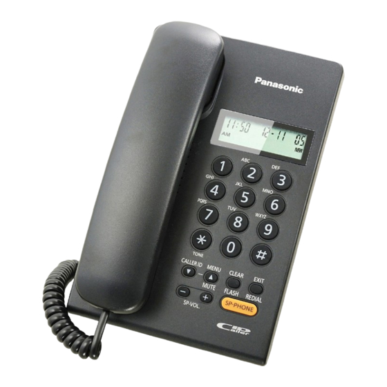
- Page 1 ORDER NO. KM41103334CE Telephone Equipment KX-TSC62SXB Model No. Caller ID Compatible KX-TSC62SXW Integrated Telephone System B: Black Version W: White Version (for India) © Panasonic System Networks Co., Ltd. 2011 Unauthorized copying and distribution is a violation of law.
- Page 2 KX-TSC62SXB/KX-TSC62SXW WARNING This service information is designed for experienced repair technicians only and is not designed for use by the general public. It does not contain warnings or cautions to advise non-technical individuals of potential dangers in attempting to service a product. Products powered by electricity should be serviced or repaired only by experienced professional technicians.
-
Page 3: Table Of Contents
KX-TSC62SXB/KX-TSC62SXW TABLE OF CONTENTS PAGE PAGE 1 Safety Precautions----------------------------------------------- 4 1.1. For Service Technicians --------------------------------- 4 2 Warning -------------------------------------------------------------- 4 2.1. About Lead Free Solder (Pbf: Pb free)--------------- 4 2.2. Discarding of P. C. Board-------------------------------- 5 3 Specifications ----------------------------------------------------- 6 4 Technical Descriptions ----------------------------------------- 7 4.1. -
Page 4: Safety Precautions
KX-TSC62SXB/KX-TSC62SXW 1 Safety Precautions 1.1. For Service Technicians • Repair service shall be provided in accordance with repair technology information such as service manual so as to pre- vent fires, injury or electric shock, which can be caused by improper repair work. -
Page 5: Discarding Of P. C. Board
KX-TSC62SXB/KX-TSC62SXW 2.1.1. Suggested PbF Solder There are several types of PbF solder available commercially. While this product is manufactured using Tin, Silver, and Copper (Sn+Ag+Cu), you can also use Tin and Copper (Sn+Cu) or Tin, Zinc, and Bismuth (Sn+Zn+Bi). Please check the manufac turer's specific instructions for the melting points of their products and any precautions for using their product with other materi- als. -
Page 6: Specifications
KX-TSC62SXB/KX-TSC62SXW 3 Specifications Power Source: From telephone line Memory Capacity: 30 Caller ID memory Redial: The unit redials the last 5 dialed numbers Speaker Unit: Unit: 5cm (2") PM Cone type 32 Handset: 3 cm (1 ") PM dynamic type 150... -
Page 7: Technical Descriptions
KX-TSC62SXB/KX-TSC62SXW 4 Technical Descriptions 4.1. Block Diagram... -
Page 8: Circuit Operation
KX-TSC62SXB/KX-TSC62SXW 4.2. Circuit Operation 4.2.1. Bell Detector Circuit When the bell signal is input from LINE to T/R (when the telephone rings), the signal is output at the buzzer via the following path : T/R C201 R201 IC201 (pin8) IC201 (pin5) R204 SW201 Buzzer 4.2.2. - Page 9 KX-TSC62SXB/KX-TSC62SXW 4.2.3. Speakerphone Circuit 4.2.3.1. Function The circuit controls the automatic switching of the transmitted and received signals, to and from the telephone line, when the unit is used in the hands -free mode. 4.2.3.2. Circuit Operation The speakerphone can only provide a one-way communication path.
- Page 10 KX-TSC62SXB/KX-TSC62SXW 4.2.4. Caller ID Detect Circuit 4.2.4.1. Function (FSK Signal) The caller ID is a changeable ID which the user of a telephone circuit obtains by entering a contract with the telephone company to utilize a caller ID service. For this reason, the operation of this circuit assumes that a caller ID service contract has been entered for the circuit being used.
-
Page 11: Location Of Controls And Components
KX-TSC62SXB/KX-TSC62SXW 5 Location of Controls and Components Refer to the Operating Instructions. Note: You can download and refer to the Operating Instructions (Instruction book) on TSN Server. 6 Installation Instructions Refer to the Operating Instructions. Note: You can download and refer to the Operating Instructions (Instruction book) on TSN Server. -
Page 12: Troubleshooting Guide
KX-TSC62SXB/KX-TSC62SXW 8 Troubleshooting Guide 8.1. Service Hints SYMPTOM CURE Dead. Check IC801, X2. Can't hear the voice from handset. Check Q401, Q431, Q433 and handset jack. No voice transmit. Check Q422, Q401 and handset jack. Can't tone dial. Check IC801 (58), C481~C484, R481~R483. -
Page 13: Tone Dialing Problems
KX-TSC62SXB/KX-TSC62SXW 8.4. Tone Dialing Problems Does the DTMF signal Can the DTMF sound Check IC801 and X2. appear at Pin56 of IC801? be monitored ? Does the DTMF signal appear at base of Q401? Check C481~C484, R481~R483 and Q401 Check Q401. -
Page 14: Disassembly And Assembly Instructions
KX-TSC62SXB/KX-TSC62SXW 9 Disassembly and Assembly Instructions 9.1. Disassembly Instructions Remove 4 Screws to remove the Cabinet Cover. 4 Screws Remove the Hook Button. Hook Button Unhook the Tel Line and Handset Jack, then remove the Main P.C. Board. Do not touch the capacitor when removing the Main P.C. - Page 15 KX-TSC62SXB/KX-TSC62SXW Remove the 2 screws to remove the Buzzer. 2 Screws 5 Remove the 3 screws to remove the Speaker. 3 Screws Speaker 6 Remove the 3 screws to remove the Operational P.C. Board. 3 Screws Operation P.C. Board...
-
Page 16: Assembly Instruction
KX-TSC62SXB/KX-TSC62SXW 9.2. Assembly Instruction 9.2.1. How to Replace the Base Unit LCD Note: • Make sure to cut the length of the rubber of the soldering iron to become 23mm to 25mm. • Preheat the soldering iron for 10 minutes for the Rubber of Soldering Iron to reached around 180~200C. - Page 17 KX-TSC62SXB/KX-TSC62SXW Heatweld with the tip of the soldering iron for 10 seconds each position (in case of 60W soldering iron) with 10kg pressure applied 3 times on position (A)~(C), as shown below. Tip of Soldering Iron (Part No. PQZZ430PIR) Rubber of Soldering Iron (Part No.
-
Page 18: Miscellaneous
KX-TSC62SXB/KX-TSC62SXW 10 Miscellaneous 10.1. IC Block diagram 10.1.1. IC801 RxD6/P113, RxD6/P12 (LINSEL) PORT 1 P11 to P14 16-bit TIMER/ TI000/P33 EVENT COUNTER 00 TO00/TI010/P34 PORT 2 P20 to P27 TOH0/P32 8-bit TIMER H0 PORT 3 P31 to P34 TOH1/P31 8-bit TIMER H1... - Page 19 KX-TSC62SXB/KX-TSC62SXW 10.1.2. RINGER IC (IC201) Vcc 1 POWER SUPPLY RSL 2 WITH HYSTERISIS LFI 3 LOW FREQ HIGH FREQ LFO 4 Pin descriptions Pin No. Pin name Name Function This is the power supply pin for the lC. It is connected to the (...
- Page 20 KX-TSC62SXB/KX-TSC62SXW 10.1.3. Speakerphone IC Data (IC601) TRANSMIT CHANNEL TRANSMIT ATTENUATOR TRANSMIT LEVEL DETECTOR TRANSMIT SIGNAL ATTENUATOR RECEIVE NOISE CONTROL COMPARATOR DETECTOR RECEIVE PEAK LEVEL LIMITER DETECTOR RECEIVE ATTENUATOR RECEIVE CHANNEL SPEAKER REGULATOR SPEAKERPHONE IC SYSTEM MC34018 Name Description A resistor to ground provides a reference current for the transmit and receive attenuators.
-
Page 21: How To Replace The Flat Package
KX-TSC62SXB/KX-TSC62SXW 10.2. How to Replace the Flat Package IC Even if you do not have the special tools (for example, a spot heater) to remove the Flat IC, with some solder (large amount), a soldering iron and a cutter knife, you can easily remove the ICs that have more than 100 pins. - Page 22 KX-TSC62SXB/KX-TSC62SXW 10.2.3. How to Install the IC 1. Temporarily fix the FLAT PACKAGE IC, soldering the two marked pins. *Check the accuracy of the IC setting with the corresponding soldering foil. 2. Apply flux to all pins of the FLAT PACKAGE IC.
-
Page 23: Terminal Guide Of The Ics, Transistors And Diodes
KX-TSC62SXB/KX-TSC62SXW 10.3. Terminal Guide of the ICs, Transistors and Diodes C1CB00002903, B0EDER000009 PNWITSC62SXH C1CB00001673 PQVINJU7014R UNR5213J0L, B1ABDF000026, B1GBJCJJ0003, B1AAKD000013, B1ACGP000007 PQVT2N6517CA 2SD1819KSL,2SB1218KSL,B1ABDM000001 Cathode Cathode Cathode Anode Anode Anode MA111, B1BCAP000026 DB2J31400L MA4056 PQVDMZJ5R1C Anode Cathode Cathode Anode MA4180 1SS133... -
Page 24: Schematic Diagram
KX-TSC62SXB/KX-TSC62SXW 11 Schematic Diagram 11.1. For Schematic Diagram 1. DC voltage measurements are takens with electronic voltmeter from negative terminal. 2. This schematic diagram may be modified at any time with the development of new technology. - Page 25 KX-TSC62SXB/KX-TSC62SXW Memo...
-
Page 26: Schematic Diagram (Main)
KX-TSC62SXB/KX-TSC62SXW 11.2. Schematic Diagram (Main) C624 C603 IC601 TP611 0.0082u R611 R606 C620 0.027u R607 R612 C609 0.1u C615 22u 16 R605 2.2M C606 0.068u R602 2.7K R613 100k C610 C619 4.7u R608 4.7k C608 0.022u TP612 R617 2.2k R609 1.8M... - Page 27 KX-TSC62SXB/KX-TSC62SXW RINGER R204 0.5W C201 R201 1u 250 6.8k IC201 C101 L101 680p 500 Q102 D101 POS101 +3.6V C102 L102 Q103 680p 500 PULSE +3.6V IC501 R521 C522 100k 0.015u C521 OUT1 WAKEUP R509 C509 R522 180k 1500p OUT2 IN-1...
-
Page 28: Schematic Diagram (Operation)
KX-TSC62SXB/KX-TSC62SXW 11.3. Schematic Diagram (Operation) -
Page 29: Printed Circuit Board
KX-TSC62SXB/KX-TSC62SXW 12 Printed Circuit Board 12.1. Circuit Board (Main) 12.1.1. Component View YELLOW GREEN C201 R201 POS101 SA101 L101 L102 R103 C101 C102 D103 SW301 Q101 Q103 Q301 Q102 Q401 R105 D106 C419 C413 D305 C618 PNLB1988Z C615 C619 R615... - Page 30 KX-TSC62SXB/KX-TSC62SXW 12.1.2. Bottom View PNLB1988Z D101 IC201 R415 R111 Q302 C321 C451 R427 C427 R523 Q421 R507 R600 IC501 C507 C433 IC601 TP402 TP401 C439 TP403 R613 TP24 TP611 TP11 TP602 MIC- MIC+ TP10 R614 WHITE BLACK RINGER KX-TSC62SX CIRCUIT BOARD (Main (Bottom View))
-
Page 31: Circuit Board (Operation)
KX-TSC62SXB/KX-TSC62SXW 12.2. Circuit Board (Operation) 12.2.1. Component View BOND PNLB1989Z C809 C808 RED WHITE KX-TSC62SX CIRCUIT BOARD (Operation (Component View)) - Page 32 KX-TSC62SXB/KX-TSC62SXW 12.2.2. Bottom View TP28 TP27 VDD0 R811 R801 R805 R808 IC801 R809 C801 C804 FLMD0 C803 C802 R621 RESET R619 KEY1 KEY2 STB3 KEY3 STB2 STB1 GND0 D808 PROG/MUTE CLEAR/FLASH EXIT/REDIAL STB4 STB5 DOWN TP11 TP13 C630 WHITE KX-TSC62SX CIRCUIT BOARD (Operation (Bottom View))
-
Page 33: Exploded View And Replacement Parts List
KX-TSC62SXB/KX-TSC62SXW 13 Exploded View and Replacement Parts List 13.1. Cabinet and Electrical Parts PCB2 PCB1 MIC1 Ref.No. Figure... -
Page 34: Accessories
KX-TSC62SXB/KX-TSC62SXW 13.2. Accessories... -
Page 35: Replacement Part List
KX-TSC62SXB/KX-TSC62SXW 13.3. Replacement Part List 1. RTL (Retention Time Limited) Safety Ref. Part No. Part Name & Description Remarks Note: PNJK1134Z KEYBOARD SWITCH, RUB- The “RTL” marking indicates that its Retention Time is BER KEY (for KX- Limited. When production is discontinued, this item... - Page 36 KX-TSC62SXB/KX-TSC62SXW Safety Ref. Part No. Part Name & Description Remarks Safety Ref. Part No. Part Name & Description Remarks R203 ERJ3GEYJ334 330k R606 ERJ3GEYJ303 R204 ERJ3GEYJ103 R607 ERJ3GEYJ683 R301 PQ4R10XJ104 100k R608 ERJ3GEYJ472 4.7k R302 ERDS2TJ472 4.7k R609 ERJ3GEYJ185 1.8M...
- Page 37 KX-TSC62SXB/KX-TSC62SXW Safety Ref. Part No. Part Name & Description Remarks Safety Ref. Part No. Part Name & Description Remarks C614 ECEA0JKA470 PQJA212M CORD, HANDSET (for KX- TSC62SXW) C615 ECEA0JKS220 PQJA10075Z CORD, TELEPHONE C616 ECUV1C104KBV 0.1 PNPK3378001Z GIFT BOX C617 ECEA0JKS470...