Epson STYLUS COLOR 3000 Service Manual
Hide thumbs
Also See for STYLUS COLOR 3000:
- User manual (286 pages) ,
- Product support bulletin (84 pages) ,
- Quick setup manual (21 pages)
Table of Contents
Advertisement
Quick Links
Advertisement
Chapters
Table of Contents

Related Manuals for Epson STYLUS COLOR 3000

Summary of Contents for Epson STYLUS COLOR 3000
- Page 1 Service Manual TM-SC3000 Epson America, Inc.
- Page 2 Service Manual Revision Date Release August 1997 EPSON Stylus COLOR 3000 Service Manual...
- Page 3 Epson America, Inc., shall not be liable against any damages or problems arising from the use of any options or any consumable products other than those designated as Original EPSON Products or EPSON-Approved Products by Seiko Epson Corporation.
- Page 4 TRADEMARKS EPSON®, ESC/P® and EPSON Stylus® are registered trademarks and ESC/P 2™ is a trademark of Seiko Epson Corporation. General Notice: Other product names used herein are for identification purposes only and may be trademarks of their respective companies. EPSON disclaims any and all rights in those marks.
- Page 5 2. Make certain that the source voltage is the same as the rated voltage listed on the serial number/rating plate. If the EPSON product has a primary AC rating different from the available power source, do not connect it to the power source.
-
Page 6: Table Of Contents
Chapter 1 Product Description Overview_____________________________________________________________________ 1-1 Options and Consumables _______________________________________________________ 1-2 Specifications _________________________________________________________________ 1-4 Printing Specifications ______________________________________________________________________1-4 Control codes ______________________________________________________________________________1-5 Character tables ____________________________________________________________________________1-5 Paper Feeding _____________________________________________________________________________1-7 Paper Handling & Specifications ______________________________________________________________1-7 Printable Area _____________________________________________________________________________1-9 Adjust Lever _____________________________________________________________________________1-12 Ink Specifications _________________________________________________________________________1-13 Input Data Buffer__________________________________________________________________________1-13 Electric Specifications ______________________________________________________________________1-14 Environmental Conditions __________________________________________________________________1-14... -
Page 7: Overview
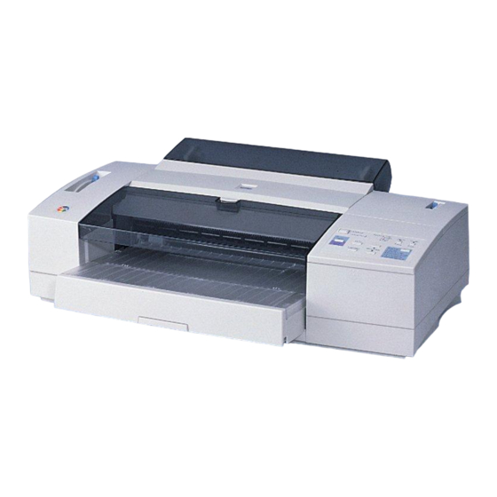
1.1 Overview The EPSON Stylus COLOR 3000 is a high-performance color ink jet printer designed for office use. It can also be used as a plotter, and can print on a wide range of paper sizes (up to A2). The main features are described below. -
Page 8: Options And Consumables
From D-SUB 9-pin (computer) to D-SUB 25-pin (printer) Banner paper holder with cutting guide C81101∗ (Banner Paper Kit) Ink Cartridges S020118 Black ink cartridge S020122 Yellow ink cartridge S020126 Magenta ink cartridge S020130 Cyan ink cartridge EPSON Stylus Color 3000 Service Manual... - Page 9 EPSON Stylus COLOR 3000 Table 1-1. Options and Consumables (continued) EPSON Special Media S041059 / S041025 EPSON 360 dpi ink jet paper (A4) S041060 EPSON 360 dpi ink jet paper (Letter) S041065/S041046 EPSON 360 dpi ink jet paper (A3) S041066/S041647...
-
Page 10: Specifications
Product Description 1.3 Specifications This section provides detailed information on the EPSON Stylus COLOR 3000. Printing Specifications Printing method On-demand ink jet Nozzle configuration Monochrome 128 nozzles (32 x 4 staggered rows) Color (magenta, cyan, yellow) 64 nozzles (32 x 2 staggered rows, each color) -
Page 11: Control Codes
EPSON Sans Serif 10 cpi, 12 cpi, 15 cpi, Proportional EPSON Courier 10 cpi, 12 cpi, 15 cpi EPSON Prestige 10 cpi, 12 cpi, 15 cpi EPSON Script 10 cpi, 12 cpi, 15 cpi EPSON Stylus Color 3000 Service Manual... - Page 12 PC 866 (Russian) PC 869 (Greek) MAZOWIA (Poland) Supported Supported Supported Code MJK (CSFR) ISO 8859-7 (Latin/Greek) ISO Latin 1T (Turkish) Bulgaria (Bulgaria) PC 774 Estonia ISO 8859-2 (ISO Latin 2) PC 866 LAT EPSON Stylus Color 3000 Service Manual...
-
Page 13: Paper Feeding
11 in. (279.4 mm) Size 8.3 in. (210 mm) 11.7 in. (297 mm) Paper Thickness 0.003 in. (0.075 mm) to 0.0033 in. (0.085 mm) Note: Print on the designated side of transparency paper and at normal temperatures. EPSON Stylus Color 3000 Service Manual... - Page 14 0.0047 in. (0.12 mm) or less (label only) Plain paper Quality Note: Make sure the paper has no creases, curls, or tears. Do not load labels in the ASF; the labels may peel off of the sheet. EPSON Stylus Color 3000 Service Manual...
-
Page 15: Printable Area
A3 landscape (5 mm) (5 mm) (3 mm) (14 mm) 17.02 in. (432 mm) 0.20 in. 0.43 in. 0.12 in. 0.55 in. ANSI B landscape (5 mm) (11 mm) (3 mm) (14 mm) ANSI C EPSON Stylus Color 3000 Service Manual... - Page 16 Figure 1-4. Printable Area for Envelopes Table 1-14. Minimum Margins for Envelopes Left Margin Right Margin Top Margin Bottom Margin 0.12 in. 0.12 in. 0.12 in. 0.55 in. 3 mm 3 mm 3 mm 14 mm 1-10 EPSON Stylus Color 3000 Service Manual...
- Page 17 Printable Area 2: Paper feed pitch is guaranteed in this area. Perforation *1 : The maximum printable width is 15 inches (381 mm). Figure 1-5. Printable Area for Continuous Paper Note: The label base sheet is not a printable area. EPSON Stylus Color 3000 Service Manual 1-11...
-
Page 18: Adjust Lever
Cut sheets Transparencies Toward rear of printer 0 in. Continuous paper Envelopes Toward front of printer + 0.028 in. (0.7 mm) Index cards PG Adjust Lever Printer Cover Figure 1-6. Adjust Lever Settings 1-12 EPSON Stylus Color 3000 Service Manual... -
Page 19: Ink Specifications
2. To use ink that is frozen (below 23 ° F (-4 ° C)); let it defrost for at least 3 hours at room temperature. Input Data Buffer Input data buffer: 64 KB EPSON Stylus Color 3000 Service Manual 1-13... -
Page 20: Electric Specifications
Resistance to shock Operating* 1 G within 1 ms † Non-operating 2 G within 2 ms Refer to the table on the next page for the guaranteed range of operation. † In shipment container. 1-14 EPSON Stylus Color 3000 Service Manual... -
Page 21: Reliability
220 - 240 V version Low Voltage Directive 73/23/EEC EN60950 EMC Directive 89/336/EEC EN55022 class B EN61000-3-2 EN61000-3-3 EN50082-1 IEC801-2 IEC801-3 IEC801-4 Acoustic Noise Noise level Approximately 45 dB (A) (According to ISO 7779) EPSON Stylus Color 3000 Service Manual 1-15... -
Page 22: Physical Specifications
(810 mm × 565 mm × 240 mm) Refer to the Appendix for details. 1.4 Interfaces The EPSON Stylus COLOR 3000 is equipped with parallel and Macintosh serial interfaces and a card slot for an optional Type-B interface. This section provides information on each interface. Parallel Interface... - Page 23 Typical time of tack is shown in Table 1-20. Table 1-20. Typical Time of Tack Parallel I/F transfer rate Typical time of tack Fast 1µs Normal 3µs EPSON Stylus Color 3000 Service Manual 1-17...
- Page 24 16,33,19-30 Signal ground. 15,34 Not connected. Notes: 1. / at the beginning of a signal means active low. 2. The I/O column indicates the direction of the signal as viewed form the printer. 1-18 EPSON Stylus Color 3000 Service Manual...
- Page 25 2. The I/O column indicates the direction of the signal as viewed form the printer. Extensibility Request The printer responds affirmatively when the extensibility request values are 00H or 04H, as follows: Request Nibble Mode Reverse Channel Transfer. Request Device ID using Nibble Mode Reverse Channel Transfer EPSON Stylus Color 3000 Service Manual 1-19...
-
Page 26: Macintosh Serial Interface
Balanced Transmit + Data terminal ready RxD+ Balanced Receive + Table 1-24. X-ON/X-OFF, DTR Protocol State Buffer space X-ON/X-OFF Busy Less than 1024 bytes Send X-OFF code Ready More than 2048 bytes Send X-ON code 1-20 EPSON Stylus Color 3000 Service Manual... -
Page 27: Optional Interface
EPSON Stylus COLOR 3000 Figure 1-9. Macintosh Serial Interface Connector Pin Assignments Optional Interface The EPSON Stylus COLOR 3000 supports an optional Type-B interface (Level 2) with the following characteristics. Reply message Using Co-ax / Twin-ax I/F card When ESC/P2 is selected:... -
Page 28: Preventing Data Transfer Time-Out
This slowdown starts when the space left in the input buffer drops below several hundred bytes. The printer becomes continuously BUSY when the input buffer is full. 1-22 EPSON Stylus Color 3000 Service Manual... -
Page 29: Interface Selection
EPSON Stylus COLOR 3000 Interface Selection The EPSON Stylus COLOR 3000 has three types of interfaces: parallel, serial, and optional Type-B. Each interface can be selected manually or automatically. Both are selected in the default setting mode. Manual selection The interface selected in default setting mode always prints out data from the host. -
Page 30: Operation
Plain Paper 5 Sec. 360 dpi Ink Jet Printer Reset Micro Adjust Photo Quality Ink Jet Paper Load/Eject Photo Quality Glossy Film Ink Jet Transparencies Other Media Selection Off Figure 1-10. Control Panel 1-24 EPSON Stylus Color 3000 Service Manual... - Page 31 When the EEPROM is reset, the waste ink drain pads need to be replaced. This must be performed by a qualified service person only. (See Chapter 3.) Indicators This printer has 13 LED printer indicators, which are shown in Table 1-29. EPSON Stylus Color 3000 Service Manual 1-25...
- Page 32 (Photo Quality Glossy Film) Media Type Green Ink jet transparencies is selected. (Ink Jet Transparencies) Media Type Green Paper type has not been selected. (Other/Media Selection Off) Note: Refer to Table 1-36 for more detailed conditions. 1-26 EPSON Stylus Color 3000 Service Manual...
-
Page 33: Default Setting
Turn the printer off to save the new settings in the EEPROM. Figure 1-11. Default Setting Flowchart CAUTION Turn the printer off after the default setting operation is run; adjustment values are stored in the EEPROM when the printer is turned off. EPSON Stylus Color 3000 Service Manual 1-27... -
Page 34: Setting Menu
On / Off Parallel I/F transfer rate Fast / Normal Note: * Underlined parameters in bold letters are factory default settings. † Refer to Table 1-31 and Table 1-32. ‡ Refer to Table 1-33. 1-28 EPSON Stylus Color 3000 Service Manual... - Page 35 1. If page length is set by ESC (C No operation Data → Eject length set by command 2. If page length is not set by ESC (C → No operation Over the paper Eject Eject length EPSON Stylus Color 3000 Service Manual 1-29...
-
Page 36: Printer Adjustment Mode
Product Description Printer Adjustment Mode The EPSON Stylus COLOR 3000 allows users to adjust the items listed in the table below. Table 1-34. Printer Adjustment Patterns Pattern No. Items Pattern 1 Uni-d adjustment at 400 cps * Pattern 2 Bi-d adjustment at 400 cps *... -
Page 37: Printer Initialization
When the printer is out of color ink, black ink is substituted to continue printing. To switch to monochrome printing mode, turn the printer off and back on. You can also select this mode with the ESC (K) command. The printer ignores the color select command, ESC r, in this mode. EPSON Stylus Color 3000 Service Manual 1-31... -
Page 38: Error Conditions
EEPROM reset. (See Table 1-28. Panel Functions when pressed simultaneously with Power On, Chapter 2 and Chapter 3.) 4. Refer to Table 1-29 for detailed conditions indicated by the Media type LED indicators. 1-32 EPSON Stylus Color 3000 Service Manual... -
Page 39: Main Components
EPSON Stylus COLOR 3000 1.6 Main Components The main components of the EPSON Stylus COLOR 3000 are as follows: Main control board C203 MAIN Power supply board C172 PSB/PSE Control panel board C203 PNL Printer mechanism M-4J60 Housing C203 Main Control Board... -
Page 40: C172 Psb/Pse Board
Housing The housing for this printer consists of the upper housing, lower housing, printer cover, ink cartridge cover, rear sheet guide, tractor unit, knob, adjust lever and release lever. 1-34 EPSON Stylus Color 3000 Service Manual... - Page 41 Chapter 2 Operating Principles Overview_____________________________________________________________________ 2-1 Printer Mechanism Operating Principles ___________________________________________ 2-1 Printer Mechanism _________________________________________________________________________2-1 Printing Mechanism ________________________________________________________________________2-2 Printhead Structure _______________________________________________________________________2-2 Printing Process__________________________________________________________________________2-3 Printing Methods _________________________________________________________________________2-3 Carriage (CR) Mechanism ___________________________________________________________________2-4 Paper Feed Mechanism ______________________________________________________________________2-5 ASF (Auto Sheet Feeder)___________________________________________________________________2-6 Tractor _________________________________________________________________________________2-7 Manual Feed Mechanism __________________________________________________________________2-7 Adjusting the Loading Position ______________________________________________________________2-7 Adjusting the Tear-off Position ______________________________________________________________2-8...
-
Page 42: Overview
Disengage Mechanism Push Tractor Mechanism PF Motor Paper Feed Mechanism ASF Mechanism (For Cut sheets only.) CR Motor CR Unit Black Color Printhead Printhead Pump Motor Pump Mechanism Figure 2-1. Printer Mechanism Block Diagram EPSON Stylus Color 3000 Service Manual... -
Page 43: Printing Mechanism
Operating Principles Printing Mechanism The printing method used for this printer is on-demand ink jet, as in other EPSON ink jet printers. However, a new type of printhead improves print quality and speed. The printing mechanism has 2 parts: the printhead and the ink cartridge. -
Page 44: Printing Process
EPSON micro dot printing Both black and color printouts can be made in EPSON micro dot printing mode. In the micro dot printing mode, the printer uses less ink to create sharper dots. This expands the gradation range for a more delicate tone. -
Page 45: Carriage (Cr) Mechanism
200 cps 0.91 0.91 0.49 0.63 0.63 100 cps 0.63 0.63 0.49 0.63 0.63 Pulley CR Motor CR Unit Timing Belt HP Sensor Sub Pulley Paper Eject Frame CR Guide Shaft Figure 2-4. CR Mechanism EPSON Stylus Color 3000 Service Manual... -
Page 46: Paper Feed Mechanism
Tractor Disengage Gear ASF Transmission Gear To the tractor. To the ASF. PF Roller Paper Eject Roller Paper Eject Out Roller PF Motor Pinion Gear PF Motor Paper Eject Mechanism Figure 2-5. Paper Feed Mechanism EPSON Stylus Color 3000 Service Manual... -
Page 47: Asf (Auto Sheet Feeder)
One-way Clutch Paper LD Rollers Paper Support ASF Transmission Gear PF Drive Roller Front PE Sensor PF Motor Pinion Gear PF Motor Figure 2-6. Auto Sheet Feeder EPSON Stylus Color 3000 Service Manual... -
Page 48: Tractor
4. Send your print job. The loading position you select remains in effect until you change it again, even when you turn off the printer. EPSON Stylus Color 3000 Service Manual... -
Page 49: Adjusting The Tear-Off Position
Envelope ,Card, Index card Front (+) + 0.7 mm PG Adjust Lever (Rear) (Front) Parallelism Adjustment Bushing Printhead Platen Surface • { Platen Gap Eccentricity CR Guide Shafts Figure 2-8. Platen Gap Adjustment Mechanism (expanded) EPSON Stylus Color 3000 Service Manual... -
Page 50: Ink System
Figure 2-9 shows a flowchart of the ink system. Ink Cartridges Cleaner Head for Black and Color Ink CR Unit Pump Motor Clutch Unit Combination Gear Pump Gear Air Valves Pump 1 Pump 2 Waste Ink Drain Pads Figure 2-9. Ink System EPSON Stylus Color 3000 Service Manual... -
Page 51: Pump
Coil resistance Connection Bipolar Active mode 2-2 phase, 1-2 phase, W1-2 phase, Constant current drive Drive frequency 281 to 1250 Hz 825 mA (at fast absorption) Drive current 500 mA (at slow absorption) 2-10 EPSON Stylus Color 3000 Service Manual... -
Page 52: Capping Mechanism
Black Ink Printhead Cap Holder Carriage Cap 2 Cap 1 To the waste ink drain pads To the waste ink drain pads Capping Unit Frame Air Valve Valve Spring Air Tube Figure 2-11. Capping Mechanism 2-11 EPSON Stylus Color 3000 Service Manual... -
Page 53: Wiping/Cr Lock Mechanism
The CR unit remains in the capping position when transported. Head Cleaner Head Cleaner Lever Printhead Pump Motor Gear Train Pump Gear/Clutch Wiping Mechanism Switch Lever Head Cleaner Lever Disengagement Mechanism CR Lock Mechanism Figure 2-12. Wiping/Carriage Lock Mechanism 2-12 EPSON Stylus Color 3000 Service Manual... -
Page 54: Electrical Circuit Operation Principles
The electrolytic capacitor determines the delay period. It continues to output +5 V and +42 V to keep the main circuit switch on the primary side active until all electric charge is discharged. The minimum delay period depends on the capacitor size, but is normally 30 seconds. 2-13 EPSON Stylus Color 3000 Service Manual... - Page 55 Output current is monitored by transistors Q81 and Q82. If the measured output current is abnormally low, there is a short circuit, and the overprotection circuit has fed back to the primary circuit to stop the switching FET operation. 2-14 EPSON Stylus Color 3000 Service Manual...
-
Page 56: C203 Main Control Board
Produces common voltage for the black printhead. IC23 Produces common voltage for the color printhead. Driver IC17 Drives the PF motor. IC18 Drives the pump motor. IC25 D/A converter for CR motor control. IC19, IC20 Drives the CR motor. 2-15 EPSON Stylus Color 3000 Service Manual... - Page 57 From IC16 CR Motor A3953 (IC19, IC20) PF Motor Driver Circuit PF Motor From IC6 UDN2917EB (IC17) Pump Motor From IC6 Driver Circuit Pump Motor UDN2917EB (IC18) Figure 2-15. Control Circuit Block Diagram 2-16 EPSON Stylus Color 3000 Service Manual...
-
Page 58: Reset Circuits
5 % of capacity. If no ink is detected and an ink cartridge is detected by the ink cartridge sensor, the ink consumption counter is reset. 2-17 EPSON Stylus Color 3000 Service Manual... - Page 59 13.76 in. ≤ W ≤ 14.47 in. (349.6 mm ≤ W ≤ 367.6 mm) 16.4 in. ≤ W ≤ 16.66 in. (416.6 mm ≤ W ≤ 423.1 mm) 16.89 in. ≤ W ≤ 17.36 in. (429.1 mm ≤ W ≤ 441 mm) 2-18 EPSON Stylus Color 3000 Service Manual...
- Page 60 ASF PL sensor, the CR PW sensor is not activated. The signal output from this sensor is sent directly to the analog port of the CPU. Figure 2-17 shows the sensor circuit block diagram. 2-19 EPSON Stylus Color 3000 Service Manual...
- Page 61 Address Bus Sensor ASF_PL0,1,2 CR_PW SWC9-11 PL Sensor CR PW Sensor PE_R Rear PE Sensor SWA0 PE_F Front PE Sensor SWA1 SWA2 HP Sensor SWA3 GAP Sensor Figure 2-17. Sensor Circuit Block Diagram 2-20 EPSON Stylus Color 3000 Service Manual...
-
Page 62: Cr Motor Driver Circuits
CR Motor OUTB CRDALD CRDASEL PHASEA OUTA CR A CRTRG ENABLE CRDA0-5 DB0-7 OUTB CR A PHASEA CR B ENAN CR B PHASEB ENBN PHASEB OUTA ENABLE OUTB Figure 2-18. CR Motor Block Diagram 2-21 EPSON Stylus Color 3000 Service Manual... -
Page 63: Pf Motor Driver Circuit
Gate Array Driver IC E05B33 UDN2917EB PF Motor (IC6) (IC17) PFA0 PF A PFA1 PFB0 PF A PFB1 PFAPH PF B PFBPH PF B FREF1/2 Figure 2-19. PF Motor Driver Circuit Block Diagram 2-22 EPSON Stylus Color 3000 Service Manual... -
Page 64: Printhead Driver Circuit
(IC 22) SCLK,SSTB,SCLR IR2C72C CCHG,CKC Common Driver CND1/2,CMD1/2 SCDATA CHCLK Cyan CHLAT Yellow YHDATA CHDATA MHDATA NCHG CHNCHG IR2C73C Magenta C203 Main Control Circuit Board Printhead Boards Figure 2-20. Printhead Driver Circuit Block Diagram 2-23 EPSON Stylus Color 3000 Service Manual... - Page 65 Printhead Drive Voltage (VH) BKC,BCHG BND0/1 BMD0/1 * Rank Value: The period of time in which the signal COM stays HIGH. Normal value is approximately 8 ms. Figure 2-21. Black Data Transmission Timing 2-24 EPSON Stylus Color 3000 Service Manual...
- Page 66 Rank Value* Printhead Drive Voltage (VH) CKC,CCHG CND0/1 CMD0/1 Rank value: The period of time in which the signal COM stays HIGH. Normal value is approximately 8 ms. Figure 2-22. Color Data Transmission Timing 2-25 EPSON Stylus Color 3000 Service Manual...
- Page 67 1-dot printing Plain paper Normal dot Normal dot Normal dot ANK, Bitmap image data 360 dpi exclusive 2-dot printing 2-dot printing OHP sheet Normal dot Normal dot Plain paper 2-26 EPSON Stylus Color 3000 Service Manual...
-
Page 68: Ink System Management
Micro Absorption Ejects bubbles formed inside the cavity. Carriage Lock Locks the carriage when turning off the printer or when no printing has been performed for at least 5 minutes with the power on. 2-27 EPSON Stylus Color 3000 Service Manual... -
Page 69: Counters
Note: The ink end sensor detects an ink end condition when the remainder of the ink drops to 5 % of the capacity. CAUTION Be sure to replace the waste ink drain pads when the EEPROM is reset. (Refer to Chapter 3.) 2-28 EPSON Stylus Color 3000 Service Manual... - Page 70 Chapter 3 Disassembly and Assembly Overview_____________________________________________________________________ 3-1 Precautions for Disassembling the Printer _______________________________________________________3-1 Tools_____________________________________________________________________________________3-2 Disassembly and Assembly ______________________________________________________ 3-3 Upper Housing Removal _____________________________________________________________________3-4 ROM Replacement _________________________________________________________________________3-6 CR PW (Paper Width) Sensor Board Removal ____________________________________________________3-6 Printhead Removal _________________________________________________________________________3-7 HP Sensor Removal _________________________________________________________________________3-9 Printer Mechanism Removal _________________________________________________________________3-10 PSB/PSE Board Removal ___________________________________________________________________3-11 C203 Main Board Removal __________________________________________________________________3-12...
-
Page 71: Overview
Risque d’esplosion si la pile est remplacée incorrectment. Ne remplacer que par une pile fu mêmetype ou d’un type équivalent recommandé par le fabricant. Eliminer les piles déchargées selon lois et les règles de sécurité en vigueur. EPSON Stylus Color 3000 Service Manual... -
Page 72: Tools
Paper width detector position tool (B4 Out) EPSON 103680000 Paper width detector position tool (Letter In) EPSON 103680100 Paper width detector position tool (Letter Out) EPSON 103680200 B4 size tool EPSON 103679700 Letter size tool EPSON 103679800 EPSON Stylus Color 3000 Service Manual... -
Page 73: Disassembly And Assembly
Edge Guide Unit CR Motor Removal Removal Removal Middle Frame Paper Quantity Sensor Pump Motor Removal Assembly Removal Removal ASF PW Sensor Paper Eject Frame Removal Removal Pump Unit Removal Figure 3-1. Printer Disassembly Procedures EPSON Stylus Color 3000 Service Manual... -
Page 74: Upper Housing Removal
Then disconnect the connector cable from the control panel and remove the control panel. Control Panel Upper Housing Connector Cable for the Control Panel Tweezers Ink Cartridge Cover Figure 3-3. Control Panel Removal EPSON Stylus Color 3000 Service Manual... - Page 75 Tractor Friction Lever Tractor CBP Screws (3X12) CBP Screw (3x12) Sheet Guide Platen Knob CBS Screw (3X6) Control Panel Hook Upper Housing Tweezers Lower Housing Hook Figure 3-4. Upper Housing Removal EPSON Stylus Color 3000 Service Manual...
-
Page 76: Rom Replacement
CBP Screws (3x8) Damper Cover Plain Washer (3X0.5X7) CR PW Sensor Cover Notch CR PW Sensor Connector Cable for the Black Printhead CR PW Sensor Board CR Unit Figure 3-5. CR PW Sensor Board Removal EPSON Stylus Color 3000 Service Manual... -
Page 77: Printhead Removal
When installing the printhead cables to the CR unit through the tube clamp, fit the square cutouts on the tube cover to the tube clamp, as shown in Figure 3-6. REQUIRED ADJUSTMENT After replacing the printhead, perform all necessary adjustments (See Chapter 4). EPSON Stylus Color 3000 Service Manual... - Page 78 Color Printhead Black Printhead Printhead Mounting Plain Washer Screw (6.3×0.2×8.3) Compression Spring (9.9) Plain Washer Color Printhead Cable (6.3×0.2×8.3) Black Printhead Cable Tube Clamp CR PW Sensor Board CR Unit Figure 3-6. Black/Color Printhead Removal EPSON Stylus Color 3000 Service Manual...
-
Page 79: Hp Sensor Removal
3. Using tweezers, release the hook securing the HP sensor to the HP sensor holder and remove the HP sensor. HP Sensor Holder Tweezers HP Sensor HP Sensor Holder HP Sensor Connector Cable HP Sensor Figure 3-7. HP Sensor Removal EPSON Stylus Color 3000 Service Manual... -
Page 80: Printer Mechanism Removal
Lubricate the top surface of the paper eject frame in an ASF printer mechanism, since the CR unit slides along a non-lubricated frame. After installing the printer mechanism, insert the waste ink draining tubes leading into the sub waste ink drain pads (See page 3-23). 3-10 EPSON Stylus Color 3000 Service Manual... -
Page 81: Psb/Pse Board Removal
AC socket; the capacitor on the C172 PSB/PSE board is still discharging electricity. Upper Shield Plate CBS Screws (3×8) CBP Screws (3×12) CBS Screws (3×8) CBS Screws (3×6) CBS Screw (3×6) PSB/PSE Board Assembly Figure 3-9. PSB/PSE Board Removal 3-11 EPSON Stylus Color 3000 Service Manual... -
Page 82: C203 Main Board Removal
When the main board is replaced, reset the EEPROM immediately to avoid failures. WARNING Be careful when servicing the lithium battery (See page 3-1). Be careful with the sharp edges of the upper shield plate. 3-12 EPSON Stylus Color 3000 Service Manual... - Page 83 Connector Cable (3×8) CBS Screws (3×8) CBS Screw (3×8) CN15 CBS Screw (3×8) Main Board CN11 CN17 CP Screws (3×6) CBS Screws (3×8) Lower Housing Upper Connector Cover Figure 3-10. C203 Main Board Removal 3-13 EPSON Stylus Color 3000 Service Manual...
-
Page 84: Main Waste Ink Drain Pad Removal
2. Remove upper housing (See page 3-4). 3. Remove the printer mechanism (See page 3-10). 4. Remove the main waste ink drain pads. Cartridge Holder Waste Ink Drain Pad Lower Housing Figure 3-11. Main Waste Ink Drain Pad Removal 3-14 EPSON Stylus Color 3000 Service Manual... -
Page 85: Paper Length) Sensor Removal
REMINDER Connect each cable to the appropriate connector. Make sure the cables are long enough to reach the proper connectors without interfering with other components. Hooks Lower Housing Figure 3-12. PL Sensor Removal 3-15 EPSON Stylus Color 3000 Service Manual... -
Page 86: Printer Mechanism Disassembly
The CR motor fan and CR motor are 2 separate parts. Therefore, mount the CR motor fan with the specified adhesive when replacing the CR motor. Leave between 0-2 mm at the end of the CR motor shaft, as shown in Figure 3-14. 3-16 EPSON Stylus Color 3000 Service Manual... -
Page 87: Pump Motor Removal
4. Remove the connector cable for the pump motor from the clamp attached to the printer mechanism. 5. Remove two screws (CBS, 3x6) securing the pump motor to the sub frame. Then remove the pump motor. Pump Motor CBS Screws (3×6) Sub Frame Assembly Figure 3-15. Pump Motor Removal 3-17 EPSON Stylus Color 3000 Service Manual... -
Page 88: Pf Motor Removal
The PF motor pinion gear is precisely machined, rusts easily, and is easily damaged. Be careful not to touch it with your bare hands or bump it against other objects. PF Motor CBS Screws (3×6) Left Frame Figure 3-16. PF Motor Removal 3-18 EPSON Stylus Color 3000 Service Manual... -
Page 89: Front/Rear Pe Sensor Removal
4. Disconnect the sensor connector cables from the sensor connectors. Rear Paper Guide Connector Cable for the Rear PE Sensor Rear PE Sensor Hooks Connector Cable for the Front PE Sensor Front PE Sensor Figure 3-17. Front/Rear PE Sensor Removal 3-19 EPSON Stylus Color 3000 Service Manual... -
Page 90: Release Sensor Removal
3. Using tweezers, release the hook securing the release sensor to the left frame. Then remove the release sensor. Release Sensor Left Frame Hook Release Sensor Connector Cable Figure 3-18. Release Sensor Removal 3-20 EPSON Stylus Color 3000 Service Manual... -
Page 91: Paper Eject Frame Removal
When removing the paper eject frame, insert a piece of clean paper between the platen surface in the paper eject frame and printheads in the CR unit to protect the printheads. CBS Screws (3×6) Paper Eject Frame CBS Screws (3×6) Printer Mechanism Figure 3-19. Paper Eject Frame 3-21 EPSON Stylus Color 3000 Service Manual... -
Page 92: Pump Removal
When attaching the head cleaner to the pump, face the rubber side of the cleaner towards the pump, as shown in Figure 3-20. When installing the pump, place the tubes into the cutout first and then insert the sub waste ink drain pads, setting the tubes between them. 3-22 EPSON Stylus Color 3000 Service Manual... -
Page 93: Edge Guide Removal
Rotary Damper Edge Guide Flange Nut (M4) Figure 3-21. Edge Guide Removal REMINDER When attaching the edge guide to the printer mechanism, connect the edge guide rack to the pinion on the damper. 3-23 EPSON Stylus Color 3000 Service Manual... - Page 94 Figure 3-22. Be sure to attach the flange nuts with the specified adhesive (See Chapter 6). Spring ottom Frame Edge Guide Rear Front Figure 3-22. Joining the Edge Guide Frame and Bottom Frame 3-24 EPSON Stylus Color 3000 Service Manual...
-
Page 95: Pq (Paper Quantity) Sensor Board Removal
Q Sensor Lever PQ Sensor Board Tension Spring (0.84) PQ Sensor Sub Lever PQ Sensor Cover Right Edge Guide Pan Camera Screw 1 (2×5.5) Pan Camera 1B Tight Screw (2×3.5) Figure 3-23. PQ Sensor Removal 3-25 EPSON Stylus Color 3000 Service Manual... -
Page 96: Asf Pw (Paper Width) Sensor Removal
ASF PW sensor sliding plate. ASF PW Sensor Cover ASF PW Sensor Board Assembly ASF PW Sensor Connector Cable Groove on the Sliding Plate Left Edge Guide Figure 3-24. ASF PW Sensor Removal 3-26 EPSON Stylus Color 3000 Service Manual... -
Page 97: Ink Cartridge Holder Removal
Coupling Screw (M6) Ink Tube CBP (3×8) CBP (3×8) CBP (3×8) Tube Fixing O-Ring CBP (3×8) CBS Screw (3×6) Yellow Magenta Cyan Black Ink Cartridge Mounting Plate Figure 3-25. Ink Cartridge Holder Removal 3-27 EPSON Stylus Color 3000 Service Manual... - Page 98 When installing ink cartridge holders, fit each holder securely into the holder on its left. The ink cartridge holder has a protection tube, which must be removed after the ink cartridge is installed. 3-28 EPSON Stylus Color 3000 Service Manual...
-
Page 99: Ink Low Sensor Removal
CB Screws (3×10) Pan Camera B Tightening Screw (2×10) Ink Cartridge Sensor Hexagon Nuts (M3) Pin Holder Pin Holder Assembly CBS Screw (3×10) Ink Low Sensor Figure 3-26. Ink Low Sensor/Ink Cartridge Sensor Removal 3-29 EPSON Stylus Color 3000 Service Manual... -
Page 100: Cr Unit Removal
Tube Mounting Plate PG Adjust Lever E-ring Plain Washer (6×0.7×12) E-ring CR Mounting Shafts Plain Washer (6×0.7×12) Printer Mechanism Parallelism Adjustment Bushings CBS Screw (3×6) Printhead Cable Guide Figure 3-27. CR Unit Removal 3-30 EPSON Stylus Color 3000 Service Manual... - Page 101 When attaching the timing belt to the CR unit, note the two parts on the belt: flat and toothed. Be sure to position the two parts carefully, as shown in Figure 3-28. CR Motor Assembly Side Timing Belt Flat Part Toothed Part Figure 3-28. Timing Belt Installation 3-31 EPSON Stylus Color 3000 Service Manual...
-
Page 102: Paper Feed Shaft Removal
CBS Screw (3×6) Tractor Release Shaft Base Frame Middle Frame Sub Tractor Release Cam Right Main Frame CBS Screws (3×6) CBS Screws (3×6) Release Transmision Lever Left Frame Figure 3-30. Base Frame Removal 3-32 EPSON Stylus Color 3000 Service Manual... - Page 103 REMINDER Engage the paper feed gear and gear 29 in the ASF gear set as shown in Figure 3-32. Don’t touch the gear surface with your bare hands; this may damage the gear. 3-33 EPSON Stylus Color 3000 Service Manual...
- Page 104 Paper Feed Gear Figure 3-32. ASF Gear Set Engagement Paper Feed Gear ASF Transmission Gear Set Bushing Paper Feed Paper Feed Rollers Shaft E-ring Bushing Edge Guide PF Roller Figure 3-33. Paper Feed Shaft Removal 3-34 EPSON Stylus Color 3000 Service Manual...
-
Page 105: Pf Roller Removal
Gear 56.4 PF Roller Bushings ASF Transmission Ratchet Trigger Transmission Lever Left Main Frame Figure 3-34. PF Roller Removal CAUTION Do not touch the gears with your bare hands; the gears may be damaged. 3-35 EPSON Stylus Color 3000 Service Manual... -
Page 106: Rear Paper Guide Removal
Paper Feed Guide Frame Hook Rear Paper Guide CBS Screw (3×6) Middle Frame Bottom Frame BS Screw (3×6) Left Main Frame Figure 3-35. Rear Paper Guide Removal 3-36 EPSON Stylus Color 3000 Service Manual... -
Page 107: Middle Frame Removal
3x8) holding the ink cartridge holder base. Then remove the middle frame. CBS Screws (3×6) Middle Frame Bottom Main Frame CBS Screw (3×8) Flange Nut LD Guide Frame Rear Paper Guide Assembly Edge Guide Figure 3-36. Middle Frame Removal 3-37 EPSON Stylus Color 3000 Service Manual... - Page 108 Chapter 4 Adjustment Overview_____________________________________________________________________ 4-1 Platen Gap Adjustment ______________________________________________________________________4-2 Market Setting Input ________________________________________________________________________4-4 Writing the Printhead IDs ____________________________________________________________________4-5 Determining the Printhead ID_______________________________________________________________4-6 Black Printhead Angular Adjustment ___________________________________________________________4-7 Printhead Vertical Adjustment ________________________________________________________________4-9 Head Gap Adjustment ______________________________________________________________________4-10 Uni-D Adjustment _________________________________________________________________________4-12 Bi-D Adjustment __________________________________________________________________________4-14 Sensor Check _____________________________________________________________________________4-16 CR-PW Sensor Initialization _______________________________________________________________4-17 PQ Sensor Adjustment____________________________________________________________________4-17...
-
Page 109: Overview
3. Bi-D adjustment Remove or replace CR 1. Uni-D adjustment motor. 2. Bi-D adjustment Note: You can not run the adjustment program without inputting the market setting first (Refer to “Market Setting Input” on page 4-4). EPSON Stylus Color 3000 Service Manual... -
Page 110: Platen Gap Adjustment
4. Use the same procedure to adjust the right parallelism adjustment bushing. CAUTION Place the thickness gauge under both printheads. Before moving the CR unit, set the PG adjust lever to “+” to open the platen gap. EPSON Stylus Color 3000 Service Manual... - Page 111 PG Set the PG lever to +. Shift the CR unit to the left end. Set the PG lever to 0. PG Adjustment Is the left PG OK? Figure 4-2. Platen Gap Adjustment Flowchart EPSON Stylus Color 3000 Service Manual...
-
Page 112: Market Setting Input
The set values are transferred to the printer when each adjustment menu is closed. Do not turn off the printer before exiting the menus you have made adjustments in. EPSON Stylus Color 3000 Service Manual... -
Page 113: Writing The Printhead Ids
Return to the main menu: select Return and press Enter. Perform other adjustments: select the desired adjustment and press Enter. 9. To exit the adjustment program, return to the main menu, select END and press Enter. EPSON Stylus Color 3000 Service Manual... -
Page 114: Determining The Printhead Id
2: Rank value 15: Printhead ID for micro dot 6. Omit the “0”s from the printhead voltage to get the printhead ID, as shown below: Black printhead ID (BK): 18216 Color printhead ID (YMC): 16215 EPSON Stylus Color 3000 Service Manual... -
Page 115: Black Printhead Angular Adjustment
When moving the printhead angle adjustment lever, lift up the tip. Fit the notch on the lever to the one of the adjusting holes to secure the set position. The printhead angle adjustment lever is delicate; be careful not to apply too much force. EPSON Stylus Color 3000 Service Manual... - Page 116 Press Return. Press the Space key. The printer prints another printhead angle adjustment pattern. ↓* The direction in which paper is fed. Figure 4-5. Printhead Angle Adjustment Flowchart EPSON Stylus Color 3000 Service Manual...
-
Page 117: Printhead Vertical Adjustment
9. To exit the adjustment program, return to the main menu, select END and press Enter.. CAUTION When moving the vertical angle adjustment lever, lift up the tip. Fit the notch on the lever to the setting hole to set the position securely. EPSON Stylus Color 3000 Service Manual... -
Page 118: Head Gap Adjustment
Return to the main menu: select Return and press Enter. Perform other adjustments: select the desired adjustment and press Enter. 9. To exit the adjustment program, return to the main menu, select END and press Enter. 4-10 EPSON Stylus Color 3000 Service Manual... - Page 119 Press the Space key to print. The printer prints another adjustment pattern in the LQ and SLQ modes. Is the Press 0 to correct printhead gap OK the value. now? Figure 4-7. Head Gap Adjustment Flowchart EPSON Stylus Color 3000 Service Manual 4-11...
-
Page 120: Uni-D Adjustment
Return to the man menu: select Return and press Enter. Perform other adjustments: select the desired adjustment and press Enter. 9. To exit the adjustment program, return to the main menu, select END and press Enter. 4-12 EPSON Stylus Color 3000 Service Manual... - Page 121 Press Return. Press the Space key to print. The printer prints another Uni-D adjustment pattern in the draft mode. Is Uni-D Press 0 to correct the value. OK now? Figure 4-8. Uni-D Adjustment Flowchart EPSON Stylus Color 3000 Service Manual 4-13...
-
Page 122: Bi-D Adjustment
Return to the main menu: select Return and press Enter. Perform other adjustments: select the desired adjustment and press Enter. 9. To exit the adjustment program, return to the main menu, select END and press Enter. 4-14 EPSON Stylus Color 3000 Service Manual... - Page 123 ↓. using ↑. Press Return. Press the Space key to print. The printer prints another Bi-D adjustment pattern. Press 0 to Bi-D OK correct the value. now? Figure 4-9. Bi-D Adjustment Flowchart EPSON Stylus Color 3000 Service Manual 4-15...
-
Page 124: Sensor Check
4. ASF Length 5. PG R. Return CAUTION If any sensors do not function properly, all LED indicators blink. In that case, check the connections between the sensors and the main control board. 4-16 EPSON Stylus Color 3000 Service Manual... -
Page 125: Cr-Pw Sensor Initialization
0.35 to 0.36 in (9 to 9.1 mm) and consists of approximately 90 sheets of 20-lb (75-g) paper. Press Enter; the Sensor Check menu appears. PQ Sensor Lever Paper Quantity Adjustment Tool 0.35 in. (9 mm) Right Edge Guide Figure 4-10. Setting the Paper Quantity Detector Adjustment Tool EPSON Stylus Color 3000 Service Manual 4-17... -
Page 126: Asf Pw Sensor Adjustment
7. Place the paper width detector adjust tool (with the A4 side out) over the right and left edge guides and adjust the left edge guide to the left end of the tool, as shown in the figure below. Then press Enter; the Sensor Check menu appears. 4-18 EPSON Stylus Color 3000 Service Manual... -
Page 127: Paper Length Sensor Adjustment
Rear Edge Guide (Up) Letter-size Paper or the Letter-size tool. Rear Edge Guide (Down) Paper Tray Extension B4-size Paper or the B4-size tool. Paper Tray Extension (Out) Figure 4-13. Setting the Letter/B4 Size Tool EPSON Stylus Color 3000 Service Manual 4-19... -
Page 128: Pg Adjustment
4. Set the PG adjust lever to the rear (-) and press Enter; the Sensor Check menu appears. 5. Select Return and press Enter; the main menu appears. 6. Select END to exit the program. 4-20 EPSON Stylus Color 3000 Service Manual... - Page 129 Chapter 5 Troubleshooting General Description ____________________________________________________________ 5-1 Unit Level Troubleshooting ______________________________________________________ 5-4 Repair of the C172 PSB/PSE Board at the Component Level _________________________ 5-10 Component Repair of the C203 Main Board _______________________________________ 5-11 M-4J60 Printer Mechanism Repair ______________________________________________ 5-15...
-
Page 130: General Description
Place one lead to Pin 1 and the other to Pin PF (Paper CN23 2 and check the coil resistance per phase. Feed) Motor Pins 2 and 4 Repeat for Pins 3 and 4. EPSON Stylus Color 3000 Service Manual... - Page 131 Analog data Maximum 10kΩ (at 24°C) Pin 2 and 3 ∗: When it is closed, the output voltage level is 2.5V or higher. †: When it is open, the output voltage level is lower than 2.5V. EPSON Stylus Color 3000 Service Manual...
- Page 132 (See pages 1-25 and 3-15.) Reset, All go on for 1 second. Timer IC reset, EEPROM Clear ∗: Corresponding Ink Out LED indicator goes on. †: All Ink Out LED indicators go on. EPSON Stylus Color 3000 Service Manual...
-
Page 133: Unit Level Troubleshooting
Print quality is poor. The printer feeds paper abnormally. Paper is jammed. Paper is fed abnormally. The top edge of loaded paper is improperly positioned. The control panel operates Buttons have no effect on the printer. abnormally. EPSON Stylus Color 3000 Service Manual... - Page 134 CN2 on the corrected? PSB/PSE board. Replace the PSB/PSE Is the voltage correct board. now? Is the problem corrected? Check the motor and driver circuits. (Refer to Section 5.5.) Figure 5-2. Flowchart (1) EPSON Stylus Color 3000 Service Manual...
- Page 135 Replace the ink drain pads and then reset the EEPROM. (Refer to Section 1.5.1 and Section 3.2.9.) Check the ink cartridge sensor and release sensor. If they are defective, replace them. Figure 5-3. Flowchart (2) EPSON Stylus Color 3000 Service Manual...
- Page 136 Is the problem corrected? Check the motors and Proceed to Section 5.5, printheads. If they are Printer Mechanism Repair. normal, replace the main control board. Is the problem corrected? Figure 5-4. Flowchart (3) EPSON Stylus Color 3000 Service Manual...
- Page 137 Check the PF motor. If normal, replace the main control board. Is the problem Clean the PF roller and the corrected? paper path. Is the problem corrected? Proceed to Section 5.5, Printer Mechanism Repair. Figure 5-5. Flowchart (5) EPSON Stylus Color 3000 Service Manual...
- Page 138 Connect the control panel properly. Is the problem corrected? Replace the control panel. Replace the control panel. Is the problem corrected? Replace the main control board. Figure 5-6. Flowchart (5) EPSON Stylus Color 3000 Service Manual...
-
Page 139: Repair Of The C172 Psb/Pse Board At The Component Level
+5 VDC is Short circuit Check the waveform at Pin 7. Replace main +does not not output. on main board. If problem operate at all. board. recurs, replace PC1 or power supply board. Waveform 5 5-10 EPSON Stylus Color 3000 Service Manual... -
Page 140: Component Repair Of The C203 Main Board
CPU (IC5) for a change in HIGH and LOW: /CS0 (Pin 1), /CS1 (Pin 2), /CS2 (Pin128), /CS3 (Pin 127) Waveform 7 CG-ROM or PROM is defective. Replace the main board or PROM. 5-11 EPSON Stylus Color 3000 Service Manual... - Page 141 (See waveform 9) CR motor is Check if the resistance of the Replace the CR defective. motor coil is as follows: motor. 5Ω ± 7 % at 25°C per phase (Refer to Table 5-1.) 5-12 EPSON Stylus Color 3000 Service Manual...
- Page 142 (Refer to the waveform 10.) PF motor is Check if the resistance of the Replace the PF motor. defective. motor coil is as follows; 10Ω ± 10 % at 25 °C (Refer to Table 5-1.) 5-13 EPSON Stylus Color 3000 Service Manual...
- Page 143 CN18:Pin 20, 21 or 22 (Refer to waveform 12.) Fuse is blown. Check the continuity of fuse F1 on Replace the main the main board. board or the fuse. Printhead is Replace the defective. printhead. 5-14 EPSON Stylus Color 3000 Service Manual...
-
Page 144: M-4J60 Printer Mechanism Repair
Rotate the pump manually and see if it Replace the pump defective. rotates with constant resistance. Check unit. if it is damaged. The printhead is Check if signals are transferred to the Replace the printhead. defective. printhead. 5-15 EPSON Stylus Color 3000 Service Manual... - Page 145 Use the driver to clean the printhead at Replace the printhead. defective. least 3 times. Run a nozzle test after each cleaning. If there’s no improvement, replace the printhead and run the self-test. 5-16 EPSON Stylus Color 3000 Service Manual...
- Page 146 If not, replace the printhead and run the Self-test. Ink cartridge is Install a new cartridge and run the Replace the ink defective. Self-test. (Because the user might cartridge. have removed and reinstalled the cartridge several times.) 5-17 EPSON Stylus Color 3000 Service Manual...
- Page 147 Symptom: The printer detects paper size incorrectly. The printer prints CR PW sensor is Load the paper and check Pins 24 and beyond the printing defective. 25 on CN21 for a change in the HIGH area. and LOW signals. 5-18 EPSON Stylus Color 3000 Service Manual...
- Page 148 Chapter 6 Maintenance Cleaning _______________________________________________________________________ 1 Service Maintenance _____________________________________________________________ 2 Head Cleaning ______________________________________________________________________________ 2 Maintenance Request_________________________________________________________________________ 2 Lubrication and Adhesion _________________________________________________________ 3...
- Page 149 Be careful not to damage any interior parts when cleaning inside the printer. When transporting the printer, be sure to remove the ink cartridges and lock the CR unit. The printer mechanism is not lubricated. Apply lubricants to the paper eject frame when replacing it. EPSON Stylus Color 3000 Service Manual...
- Page 150 In this case, reset the EEPROM. (Refer to Chapter 1.) CAUTION Replace the waste ink drain pads when resetting the EEPROM. (Refer to Chapter 3) EPSON Stylus Color 3000 Service Manual...
- Page 151 CR guide shaft – Evenly and thinly over the whole shaft surface Slope on the tractor release cam G-26 (3-5 g) 8 points on the top edge of the paper eject frame G-26 (10-20 g) EPSON Stylus Color 3000 Service Manual...
- Page 152 Point where the CR motor fan is attached to the CR motor shaft Right and left hexagon nuts in the edge guide unit CAUTION Do not apply too much lubricant or adhesive to avoid printer malfunction. EPSON Stylus Color 3000 Service Manual...
- Page 153 EPSON Stylus COLOR 3000 Figure 6-1. Lubrication Points (1) EPSON Stylus Color 3000 Service Manual...
- Page 154 Maintenance Figure 6-2. Lubrication Points (2) EPSON Stylus Color 3000 Service Manual...
- Page 155 EPSON Stylus COLOR 3000 CR Motor CR Motor Fan Indent side facing outside Figure 6-3. Adhesion Points EPSON Stylus Color 3000 Service Manual...
- Page 156 Appendix Connector Summary _____________________________________________________________ A-1 Connector Pin Assignments____________________________________________________________________ A-2 Circuit Diagrams________________________________________________________________ A-8 Component Layout _____________________________________________________________ A-13 Exploded Diagrams_____________________________________________________________ A-17 Dimensions and Weight _________________________________________________________ A-21...
- Page 157 Ink End/Cartridge Sensor (Yellow) CN12 Ink End/Cartridge Sensor (Cyan) CN13 Ink End /Cartridge Sensor (Black) CN14 PF Motor CN23 CN22 CR Motor CN20 Pump Motor C203 PNL Figure A-1. Electrical Interconnection of the Main Components EPSON Stylus Color 3000 Service Manual...
- Page 158 C203 PNL Board CN18 Color printhead CN20 Pump motor CN21 Black printhead CN22 CR motor CN23 PF motor C172 PSB/PSE Board AC power input DC power input C203 PNL Board To C203 Main-B board EPSON Stylus Color 3000 Service Manual...
- Page 159 Ground IC_M1 Ink end sensor signal Ground Table A-7. Connector Pin Assignments (CN8) Pin No. Signal Name Description ASF_PW ASF PW sensor signal + 5 VDC Ground EPSON Stylus Color 3000 Service Manual...
- Page 160 Ground IC_C1 Ink end sensor signal Ground Table A-13. Connector Pin Assignments (CN14) Pin No. Signal Name Description IC_B0 Ink cartridge sensor signal Ground IC_B1 Ink end sensor signal Ground EPSON Stylus Color 3000 Service Manual...
- Page 161 SW 6 SW 6 signal SW 7 SW 7 signal + 5 VDC PWS signal Power scan signal LED 10 LED 10 signal LED 11 LED 11 signal LED 12 LED 12 signal EPSON Stylus Color 3000 Service Manual...
- Page 162 Common output VHPR Drive voltage VHPR Drive voltage Table A-17. Connector Pin Assignments (CN20) Pin No. Signal Name Description Phase A output Phase / A output Phase B output Phase / B output EPSON Stylus Color 3000 Service Manual...
- Page 163 Phase/ A output Phase B output Phase / B output Table A-20. Connector Pin Assignments (CN23) Pin No. Signal Name Description Phase A output Phase / A output Phase B output Phase / B output EPSON Stylus Color 3000 Service Manual...
- Page 164 EPSON Stylus COLOR 3000 A.2 Circuit Diagrams Figure A-2. C203 MAIN-B Board Circuit Diagram (1/2) EPSON Stylus Color 3000 Service Manual...
- Page 165 Appendix Figure A-3. C203 MAIN-B Board Circuit Diagram (2/2) EPSON Stylus Color 3000 Service Manual...
- Page 166 LED0 LED1 LED2 LED3 LED4 LED5 LED6 LED7 LED8 LED9 LED10 LED11 LED12...
- Page 171 Appendix Figure A-9. C172 PSB Board Component Layout Figure A-10. C203 PNL Board Component Layout A-15 EPSON Stylus Color 3000 Service Manual...
- Page 172 EPSON Stylus COLOR 3000 Figure A-11. C172 PSE Board Component Layout A-16 EPSON Stylus Color 3000 Service Manual...
- Page 177 31.8 in (W) ×22.2 in (D) × 9.4 in (H) Dimension 810 mm (W) × 565 mm (D) × 240 mm (H) Weight 49.6 lb (22.5 Kg) Figure A-16 illustrates the exterior dimension of the Stylus COLOR 3000. 385 mm (15.1") 240 mm (9.4") 793 mm (31.2") 380 mm (14.9")