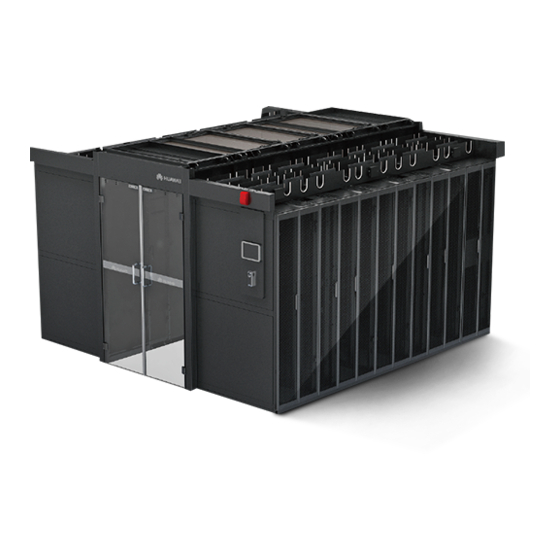
Huawei FusionModule5000 Maintenance Manual
Smart modular data center
Hide thumbs
Also See for FusionModule5000:
- Installation manual (250 pages) ,
- Commissioning manual (137 pages) ,
- Product description (123 pages)

Related Manuals for Huawei FusionModule5000


Summary of Contents for Huawei FusionModule5000
- Page 1 FusionModule5000 Smart Modular Data Center V100R001 Maintenance Guide (ECC800) Issue Date 2019-03-05 HUAWEI TECHNOLOGIES CO., LTD.
- Page 2 Notice The purchased products, services and features are stipulated by the contract made between Huawei and the customer. All or part of the products, services and features described in this document may not be within the purchase scope or the usage scope. Unless otherwise specified in the contract, all statements, information, and recommendations in this document are provided "AS IS"...
-
Page 3: About This Document
About This Document About This Document Purpose This document describes FusionModule5000 Smart Modular Data Center (smart module for short) in terms of the routine maintenance, alarm references, troubleshooting, and parts replacement, which helps maintenance personnel to inspect and maintain the smart module and eliminate potential risks promptly. - Page 4 FusionModule5000 Smart Modular Data Center Maintenance Guide (ECC800) About This Document Symbol Description Indicates a potentially hazardous situation which, if not avoided, could result in equipment damage, data loss, performance deterioration, or unanticipated results. NOTICE is used to address practices not related to personal injury.
-
Page 5: Table Of Contents
FusionModule5000 Smart Modular Data Center Maintenance Guide (ECC800) Contents Contents About This Document ......................ii 1 O&M Preparations ........................ 1 1.1 O&M Personnel Skill Requirements ........................... 1 1.2 Tools....................................... 2 1.3 Technical Documentation Preparations ..........................4 2 Routine Maintenance ......................6 2.1 System Maintenance ................................ - Page 6 FusionModule5000 Smart Modular Data Center Maintenance Guide (ECC800) Contents 2.6.15 Routine Maintenance for the Skylight System ......................39 2.6.16 Routine Maintenance for the Access Control System ....................40 2.6.16.1 Routine Maintenance for the Access Actuator......................40 2.6.16.2 Routine Maintenance for the Access Control Device ....................42 2.6.16.3 Routine Maintenance for the Sliding Door Magnetic Lock ..................
- Page 7 FusionModule5000 Smart Modular Data Center Maintenance Guide (ECC800) Contents 5.1.3 Parts Replacement for the New Main Way ........................118 5.1.3.1 Replacing the Power Distribution Unit ........................118 5.1.3.2 Replacing the Busbar Trunking Unit .........................120 5.1.3.3 Replacing the General Input Unit ..........................122 5.2 Replacing Cooling System Components .........................126...
- Page 8 FusionModule5000 Smart Modular Data Center Maintenance Guide (ECC800) Contents 5.5.19 Replacing an Access Control Device .........................177 5.5.20 Replacing a Sliding Door Magnetic Lock........................178 5.5.21 Replacing a Double-Door Magnetic Lock .........................179 5.5.22 Replacing a Button ..............................185 5.5.23 Replacing a Door Status Sensor..........................186 5.5.24 Replacing a Pad ................................187...
-
Page 9: M Preparations
FusionModule5000 Smart Modular Data Center Maintenance Guide (ECC800) 1 O&M Preparations O&M Preparations 1.1 O&M Personnel Skill Requirements Table 1-1 describes the skill requirements for the smart module O&M personnel. Table 1-1 Smart module O&M personnel skill requirements Domain Personnel Skill Requirement... -
Page 10: Tools
FusionModule5000 Smart Modular Data Center Maintenance Guide (ECC800) 1 O&M Preparations 1.2 Tools Table 1-2 lists the tools required for maintenance. Table 1-2 Tools and instruments Tool Name, Specifications, and Appearance Protective gloves Marker Measuring tape (5 Level Step ladder (2 m) - Page 11 FusionModule5000 Smart Modular Data Center Maintenance Guide (ECC800) 1 O&M Preparations Tool Name, Specifications, and Appearance Needle-nose pliers Diagonal pliers RJ45 crimping tool Crimping tool Wire stripper Hydraulic pliers Wire clippers Nylon cable tie Multimeter Electroprobe Brush Hammer Vacuum cleaner...
-
Page 12: Technical Documentation Preparations
FusionModule5000 Smart Modular Data Center Maintenance Guide (ECC800) 1 O&M Preparations Tool Name, Specifications, and Appearance 1.3 Technical Documentation Preparations Before maintenance, prepare the following documents in addition to this document. Table 1-3 Preparing maintenance documents Documentation Function Obtaining Method... - Page 13 FusionModule5000 Smart Modular Data Center Maintenance Guide (ECC800) 1 O&M Preparations Documentation Function Obtaining Method (Remarks) Precision Power and maintain the device. Distribution Cabinet User Manual(1100 mm Deep) Issue 01 (2019-03-05) Huawei Proprietary and Confidential Copyright © Huawei Technologies Co., Ltd.
-
Page 14: Routine Maintenance
FusionModule5000 Smart Modular Data Center Maintenance Guide (ECC800) 2 Routine Maintenance Routine Maintenance 2.1 System Maintenance Table 2-1 Monthly maintenance System Component Item Power Precision PDC Check the three-phase power indicators. supply and Check the SPD module. distribution system Check the LCD screen on the PDC. - Page 15 FusionModule5000 Smart Modular Data Center Maintenance Guide (ECC800) 2 Routine Maintenance System Component Item Check that the valve does not leak. Check that screws fastening the condensate pump and the water sensor are secure. Check that the water pan filter is clean and not blocked.
- Page 16 FusionModule5000 Smart Modular Data Center Maintenance Guide (ECC800) 2 Routine Maintenance System Component Item distribution humidity of the PDC. system Integrated UPS Cleanness Parameter configuration Status record Check whether battery screws are tightened. Cables between batteries Battery voltage Perform a shallow discharge test (recommended).
- Page 17 FusionModule5000 Smart Modular Data Center Maintenance Guide (ECC800) 2 Routine Maintenance System Component Item Check that the screws on the fan are not loose or distorted. Check that wiring terminals are secure. Check and fasten all circuit connections. Remove the dust.
-
Page 18: Routine Maintenance For The Structural System
FusionModule5000 Smart Modular Data Center Maintenance Guide (ECC800) 2 Routine Maintenance System Component Item breakers work properly. Check the cable insulation performance. Check the insulation resistance of the secondary loop. New main way Check the dust on the face of the new main way. -
Page 19: Routine Maintenance For The Power Supply And Distribution System
FusionModule5000 Smart Modular Data Center Maintenance Guide (ECC800) 2 Routine Maintenance Maintenance Maintenance Operation Expected Troubleshooti Item Interval Result end door, and check whether the door can be opened and closed smoothly and whether the door closer is normal. 1. Check... - Page 20 Powering off the PDC may interrupt all services. Before disconnecting power, ensure that related emergency plans have been worked out and permissions have obtained from parties involved. Huawei bears no responsibility for any accidents or loss. Table 2-6 Routine maintenance for the PDC...
-
Page 21: Integrated Ups Routine Maintenance
FusionModule5000 Smart Modular Data Center Maintenance Guide (ECC800) 2 Routine Maintenance Maintenance Maint Operation Expected Exception Handling Item enanc Guide Result Interv the PDC observation rodent professional for advice. movements in the PDC. Quarter Visual The exterior Take measures depending... - Page 22 Customers are not allowed to maintain the components inside protective covers that could only be removed using tools. If the components are to be maintained, contact Huawei technical support. Only maintenance engineers are allowed to maintain the power module and bypass module.
- Page 23 FusionModule5000 Smart Modular Data Center Maintenance Guide (ECC800) 2 Routine Maintenance Mainten Maintenance Period Standard Troubleshooting ance Item parameters are within their normal ranges, and no fault or alarm information is displayed. Cleanlines Quarterly Wipe the cabinet Remove the dust,...
-
Page 24: Routine Maintenance For Batteries
FusionModule5000 Smart Modular Data Center Maintenance Guide (ECC800) 2 Routine Maintenance To prevent system failures caused by the deterioration of some key UPS components, you are advised to check the key components on a regular basis and replace them within the service life. - Page 25 FusionModule5000 Smart Modular Data Center Maintenance Guide (ECC800) 2 Routine Maintenance Mainten Maintenance Period Standard Troubleshooting ance Item alarm alarm is generated. alarm based on the manageme alarm information. 1. The surface is clean Battery Monthly If the battery and tidy without...
- Page 26 FusionModule5000 Smart Modular Data Center Maintenance Guide (ECC800) 2 Routine Maintenance Mainten Maintenance Period Standard Troubleshooting ance Item voltage and float charging voltage are correctly set for the UPS. 3. If the fault persists, contact Huawei technical support. Battery Quarterly...
-
Page 27: Power Distribution System Maintenance
FusionModule5000 Smart Modular Data Center Maintenance Guide (ECC800) 2 Routine Maintenance Mainten Maintenance Period Standard Troubleshooting ance Item technical support. 1. Locate the cause Capacity Annually When the UPS is when an exception is Test backed up, discharge a identified. - Page 28 FusionModule5000 Smart Modular Data Center Maintenance Guide (ECC800) 2 Routine Maintenance Maintenance Maint Operation Expected Troubleshooti Item enance Result Interv Power indicator Monthl Observe the The indicators If the power indicator are on. supply is normal luminance. but an indicator...
-
Page 29: Routine Maintenance For The New Main Way
2.3.3 Routine Maintenance for the New Main Way The power-off operation may interrupt all services. Before the power-off operation, ensure that emergency plans have been worked out and approved by parties involved. Huawei bears no responsibility for any accidents or loss. -
Page 30: Routine Maintenance For The Cooling System
FusionModule5000 Smart Modular Data Center Maintenance Guide (ECC800) 2 Routine Maintenance Maintenance Operation Standard Troubleshooting Item nten ance Peri Check the Quart Point Operating Check whether the air operating erly thermometer temperatu conditioner and dehumidifier re: –10° C temperature and... - Page 31 FusionModule5000 Smart Modular Data Center Maintenance Guide (ECC800) 2 Routine Maintenance Table 2-12 Routine maintenance Operation Troubleshooting Period Result □Passed. Check whether an air Clean (water can be used) or Monthl filter is blocked. replace the air filter. □Failed. □Passed.
- Page 32 FusionModule5000 Smart Modular Data Center Maintenance Guide (ECC800) 2 Routine Maintenance Operation Troubleshooting Period Result are working properly. Five seconds later two condensate pump would start. Put down the two floats. Do not hold the two floats up so long, to avoid pumping air for a long time.
- Page 33 FusionModule5000 Smart Modular Data Center Maintenance Guide (ECC800) 2 Routine Maintenance Operation Troubleshooting Period Result To avoid burns, do not touch the electric heater surface with bare skin. □Passed. Choose Maint > If the chilled water valve handle Quarterl Diagnostic Mode >...
- Page 34 FusionModule5000 Smart Modular Data Center Maintenance Guide (ECC800) 2 Routine Maintenance Operation Troubleshooting Period Result □Passed. Check whether the Replace the components or Semi-an display panel, humidity cables. nual □Failed. and temperature sensor or cables is aging on the surface.
-
Page 35: Routine Maintenance For The Intelligent Battery Monitoring System
FusionModule5000 Smart Modular Data Center Maintenance Guide (ECC800) 2 Routine Maintenance 2.5 Routine Maintenance for the Intelligent Battery Monitoring System Only trained personnel are allowed to maintain the intelligent battery monitoring system of the data center. For safety requirements, see safety precautions in iBAT 2.0-CIM01C2 User Manual. -
Page 36: Routine Maintenance For The Management System
The cable to the HALL current monitoring port is connected securely. If the fault persists, contact Huawei technical support. 2.6 Routine Maintenance for the Management System 2.6.1 ECC800 Routine Maintenance Table 2-14 Routine maintenance for the PSU in the ECC800 Maintenanc... -
Page 37: Routine Maintenance For The Lan Switch
FusionModule5000 Smart Modular Data Center Maintenance Guide (ECC800) 2 Routine Maintenance Maintenanc Baseline Requirement Troubleshooting e Item Connection Intact Replace damaged cables. Table 2-15 Routine maintenance for the PMU in the ECC800 Maintenanc Baseline Requirement Troubleshooting e Item The PMU indicator is steady... -
Page 38: Routine Maintenance For The Vcn500
FusionModule5000 Smart Modular Data Center Maintenance Guide (ECC800) 2 Routine Maintenance Maintenan Maintenan Method Expected Exception Handling ce Item ce Period Result indicator is the board power supply is indicator on blinking abnormal when the switch the switch. green. is configured with one PSU. -
Page 39: Routine Maintenance For The 2.4G Antenna
FusionModule5000 Smart Modular Data Center Maintenance Guide (ECC800) 2 Routine Maintenance Maintenance Maintenance Operation Standard Troubleshooti Item Period Check the Monthly Observe the The VCN500 See the VCN500 VCN500 indicator is delivered indicator. indicator. steady green. documents. 2.6.4 Routine Maintenance for the 2.4G Antenna Table 2-18 Routine maintenance for the 2.4G antenna... -
Page 40: Routine Maintenance For The Smart Eth Gateway
FusionModule5000 Smart Modular Data Center Maintenance Guide (ECC800) 2 Routine Maintenance 2.6.6 Routine Maintenance for the Smart ETH Gateway Table 2-20 Routine maintenance for the smart ETH gateway Maintenance Maintenance Operation Standard Troubleshooti Item Period Check the Quarterly Observe the ... -
Page 41: Routine Maintenance For The Pad
FusionModule5000 Smart Modular Data Center Maintenance Guide (ECC800) 2 Routine Maintenance Maintenance Maintenance Operation Standard Troubleshooti Item Period Group > gateway is communication Smart ETH normal. s cable is loose Gateway to enter the disconnected. If operating so, reconnect information the cable. -
Page 42: Routine Maintenance For The Wifi Antenna
FusionModule5000 Smart Modular Data Center Maintenance Guide (ECC800) 2 Routine Maintenance Maintenance Maintenance Operation Standard Troubleshooti Item Period replace the pad. 2.6.8 Routine Maintenance for the WiFi Antenna Table 2-22 Routine maintenance for the WiFi antenna Maintenance Maintenance Operation Standard... -
Page 43: Routine Maintenance For The Ac Actuator
FusionModule5000 Smart Modular Data Center Maintenance Guide (ECC800) 2 Routine Maintenance Maintenance Maintenance Operation Standard Troubleshooti Item Period intervals, the s cable or WiFi communication converter. is interrupted. 2.6.10 Routine Maintenance for the AC Actuator Table 2-24 Routine maintenance for the AC actuator... -
Page 44: Routine Maintenance For Cameras
FusionModule5000 Smart Modular Data Center Maintenance Guide (ECC800) 2 Routine Maintenance Maintenance Maintenance Operation Standard Troubleshooti Item Period referring to ECC800 Alarm Reference V100R001. Check the Semi-annually On the WebUI Lights in the If the lights availability of of the ECC800,... -
Page 45: Routine Maintenance For The Multi-Functional Sensor
FusionModule5000 Smart Modular Data Center Maintenance Guide (ECC800) 2 Routine Maintenance Maintenance Maintenance Operation Expected Troubleshooti Item Interval Result Camera. 2.6.12 Routine Maintenance for the Multi-Functional Sensor Table 2-26 Routine maintenance for the multi-functional sensor Maintenance Maintenance Operation Standard Troubleshooti... -
Page 46: Routine Maintenance For Water Sensors
FusionModule5000 Smart Modular Data Center Maintenance Guide (ECC800) 2 Routine Maintenance Maintenance Maintenance Operation Standard Troubleshooti Item Period clear the alarm by referring to ECC800 Alarm Reference V100R001. 2.6.13 Routine Maintenance for Water Sensors Table 2-27 Routine maintenance for water sensors... -
Page 47: Routine Maintenance For The Skylight System
FusionModule5000 Smart Modular Data Center Maintenance Guide (ECC800) 2 Routine Maintenance Maintenance Maintenance Operation Standards Troubleshooti Item Period unit on the temperature WebUI. sensor. 2.6.15 Routine Maintenance for the Skylight System Table 2-29 Routine maintenance for the skylight system Maintenance... -
Page 48: Routine Maintenance For The Access Control System
FusionModule5000 Smart Modular Data Center Maintenance Guide (ECC800) 2 Routine Maintenance Maintenance Maintenance Operation Standard Troubleshooti Item Period If the ALM indicator is steady on, clear the alarm by referring to ECC800 Alarm Reference V100R001. Check the Semi-annually On the WebUI... - Page 49 FusionModule5000 Smart Modular Data Center Maintenance Guide (ECC800) 2 Routine Maintenance Maintenance Maintenance Operation Standard Troubleshooti Item Period abnormal. If gateway is the RUN indicator energized. If blinks slowly, the reconnect access the cable. If actuator is not, replace running the access normally.
-
Page 50: Routine Maintenance For The Access Control Device
FusionModule5000 Smart Modular Data Center Maintenance Guide (ECC800) 2 Routine Maintenance Maintenance Maintenance Operation Standard Troubleshooti Item Period lock. 2.6.16.2 Routine Maintenance for the Access Control Device Table 2-31 Routine maintenance for the access control device Maintenance Maintenance Operation Standard... -
Page 51: Routine Maintenance For The Sliding Door Magnetic Lock
FusionModule5000 Smart Modular Data Center Maintenance Guide (ECC800) 2 Routine Maintenance 2.6.16.3 Routine Maintenance for the Sliding Door Magnetic Lock Table 2-32 Routine maintenance for the sliding door magnetic lock Maintenance Maintenance Operation Standard Troubleshooti Item Period Check the Semi-annually Open the door. -
Page 52: Routine Maintenance For The Emergency Button
FusionModule5000 Smart Modular Data Center Maintenance Guide (ECC800) 2 Routine Maintenance 2.6.16.5 Routine Maintenance for the Emergency Button Table 2-34 Routine maintenance for the emergency button Maintenance Maintenance Operation Standard Troubleshooti Item Period Check the Semi-annually Open the door The door opens... -
Page 53: Routine Maintenance For The Electronic Cabinet Lock
FusionModule5000 Smart Modular Data Center Maintenance Guide (ECC800) 2 Routine Maintenance Maintenance Maintenance Operation Standard Troubleshooti Item Period buttons. instead of the light buttons, check whether the cable is properly connected to the light buttons one by one. If not, reconnect the cable. -
Page 54: Routine Maintenance For The Door Status Sensor
FusionModule5000 Smart Modular Data Center Maintenance Guide (ECC800) 2 Routine Maintenance 2.6.19 Routine Maintenance for the Door Status Sensor Table 2-38 Routine maintenance for the door status sensor Maintenance Maintenance Operation Standard Troubleshooti Item Period Check the Quarterly Open and close... -
Page 55: Routine Maintenance For The Fire Extinguishing System
FusionModule5000 Smart Modular Data Center Maintenance Guide (ECC800) 2 Routine Maintenance Maintenance Maintenance Operation Standard Troubleshooti Item Period interrupted. ions cable is loose or The ALM disconnecte indicator is d or whether off. the smart gateway is energized. ... -
Page 56: Routine Maintenance For The Alarm Beacon
FusionModule5000 Smart Modular Data Center Maintenance Guide (ECC800) 2 Routine Maintenance Maintena Mainte Operation Expected Troubleshooting nce Item nance Result Period detector the indicator on blinks once every 6 seconds or does not indicator the smoke every 6 seconds. blink, the smoke detector is... - Page 57 FusionModule5000 Smart Modular Data Center Maintenance Guide (ECC800) 2 Routine Maintenance Item Maintenance Method Expected Exception Period Result Handling with a smoke detector. Issue 01 (2019-03-05) Huawei Proprietary and Confidential Copyright © Huawei Technologies Co., Ltd.
-
Page 58: Alarm Reference
For details about component alarms for the power supply and distribution system, see the delivered documents. When unpacking the equipment, collect the delivered documents. If the alarm is not cleared after performing operations described in related documents, contact Huawei technical support. - Page 59 FusionModule5000 Smart Modular Data Center Maintenance Guide (ECC800) 3 Alarm Reference Alarm Alarm Impact Possible Solutions Name Severity Cause is different from A cable replace the the configured monitoring board number. become by referring to loose. 5.1.1.5 Replacing the Monitoring Board.
- Page 60 FusionModule5000 Smart Modular Data Center Maintenance Guide (ECC800) 3 Alarm Reference Alarm Alarm Impact Possible Solutions Name Severity Cause Main input Critical The mains switch The back-end Check whether the breaker has tripped. back-end current is tripping short-circuited short-circuited or...
- Page 61 FusionModule5000 Smart Modular Data Center Maintenance Guide (ECC800) 3 Alarm Reference Alarm Alarm Impact Possible Solutions Name Severity Cause current (multiple: 0.8–1). Min. main Warning A phase input input cur. current of a route exceed is lower than 0.6 time of the rated current (multiple: 0.6–0.8).
- Page 62 FusionModule5000 Smart Modular Data Center Maintenance Guide (ECC800) 3 Alarm Reference Alarm Alarm Impact Possible Solutions Name Severity Cause Min. br. cur. Warning The current of a exceed branch exceeds 0.6 time of the rated current (multiple: 0.6–0.8; confirmation time: 1–10s).
-
Page 63: Integrated Ups Alarm Reference
FusionModule5000 Smart Modular Data Center Maintenance Guide (ECC800) 3 Alarm Reference 3.1.2 Integrated UPS Alarm Reference Alar Alarm Sever System Action Cause Solution Name (Ala 1. Check whether 0001 Mains Minor If there is no Cable cables to mains... - Page 64 FusionModule5000 Smart Modular Data Center Maintenance Guide (ECC800) 3 Alarm Reference Alar Alarm Sever System Action Cause Solution Name (Ala voltage is less than 80 V, the mains voltage is abnormal; if the mains voltage exceeds 88 V, the power...
- Page 65 FusionModule5000 Smart Modular Data Center Maintenance Guide (ECC800) 3 Alarm Reference Alar Alarm Sever System Action Cause Solution Name (Ala module. 1. The system 1. Check the 0010 Abnor Minor The bypass cannot transfer bypass input voltage range to bypass mode.
- Page 66 FusionModule5000 Smart Modular Data Center Maintenance Guide (ECC800) 3 Alarm Reference Alar Alarm Sever System Action Cause Solution Name (Ala based on the 2. Check that the current power neutral wire to supply status the power and logic. distribution system is normal.
- Page 67 FusionModule5000 Smart Modular Data Center Maintenance Guide (ECC800) 3 Alarm Reference Alar Alarm Sever System Action Cause Solution Name (Ala 1. The current 1. Check whether 0025 Battery Minor limit value is battery overvol configured derated when parameters are...
- Page 68 FusionModule5000 Smart Modular Data Center Maintenance Guide (ECC800) 3 Alarm Reference Alar Alarm Sever System Action Cause Solution Name (Ala related power module. 1. Check whether 0530 Battery Critic The system The battery the positive and ground generates alarm...
- Page 69 FusionModule5000 Smart Modular Data Center Maintenance Guide (ECC800) 3 Alarm Reference Alar Alarm Sever System Action Cause Solution Name (Ala addition, the threshold. batteries discharger matches the cannot be actual number. configured started. If the 3. Check that the...
- Page 70 FusionModule5000 Smart Modular Data Center Maintenance Guide (ECC800) 3 Alarm Reference Alar Alarm Sever System Action Cause Solution Name (Ala system will be is obstructed. the fan is overloaded after abnormal. the module Replace the shuts down, the power module if system will the fan is faulty.
- Page 71 FusionModule5000 Smart Modular Data Center Maintenance Guide (ECC800) 3 Alarm Reference Alar Alarm Sever System Action Cause Solution Name (Ala r alarm shuts down the waveform is modules module. abnormal. generate the alarm, start the 2. If only one UPS and transfer...
- Page 72 FusionModule5000 Smart Modular Data Center Maintenance Guide (ECC800) 3 Alarm Reference Alar Alarm Sever System Action Cause Solution Name (Ala seconds later. short-circuits. The inverter bridge short-circuits. 1. Check that there 0566 Output Minor If the overload The load is is no overload.
- Page 73 FusionModule5000 Smart Modular Data Center Maintenance Guide (ECC800) 3 Alarm Reference Alar Alarm Sever System Action Cause Solution Name (Ala bypass mode. transfers to bypass mode. 0088 Rack Critic None. The configured Check the rack address rack address address setting.
- Page 74 FusionModule5000 Smart Modular Data Center Maintenance Guide (ECC800) 3 Alarm Reference Alar Alarm Sever System Action Cause Solution Name (Ala 0337 Critic None. The bypass input Running status bypass circuit breaker on displayed. No input the PDC is OFF. suggested measures.
- Page 75 FusionModule5000 Smart Modular Data Center Maintenance Guide (ECC800) 3 Alarm Reference Alar Alarm Sever System Action Cause Solution Name (Ala battery circuit breaker is displayed. See circuit OFF. details about how to breaker handle other alarms. is OFF. 0335 Genera Warni None.
- Page 76 FusionModule5000 Smart Modular Data Center Maintenance Guide (ECC800) 3 Alarm Reference Alar Alarm Sever System Action Cause Solution Name (Ala 1. Check that the 0098 Bypass Minor When the system The output output and current works in ECO and input...
- Page 77 FusionModule5000 Smart Modular Data Center Maintenance Guide (ECC800) 3 Alarm Reference Alar Alarm Sever System Action Cause Solution Name (Ala self-check. is complete. 0148 Minor None. Restore the ATS fault communicatio communications ns parameters parameters to are modified.
- Page 78 FusionModule5000 Smart Modular Data Center Maintenance Guide (ECC800) 3 Alarm Reference Alar Alarm Sever System Action Cause Solution Name (Ala urrent overcurrent. 0200 Branch Warni None. A branch Check the branch underc experienced loads. urrent overcurrent. 0370 Branch Critic None.
-
Page 79: Power Distribution Unit Alarm Reference
FusionModule5000 Smart Modular Data Center Maintenance Guide (ECC800) 3 Alarm Reference Alar Alarm Sever System Action Cause Solution Name (Ala 3.1.3 Power Distribution Unit Alarm Reference Alarm ID Alarm Name Alarm Possible Solution severity Cause 0x5001 Communication Critical Communication Check the cable... - Page 80 FusionModule5000 Smart Modular Data Center Maintenance Guide (ECC800) 3 Alarm Reference Alarm ID Alarm Name Alarm Possible Solution severity Cause supply pin short-circuited. of the third branch is not short-circuit 1. Check that 0x5013 Fourth output Major The output of...
- Page 81 FusionModule5000 Smart Modular Data Center Maintenance Guide (ECC800) 3 Alarm Reference Alarm ID Alarm Name Alarm Possible Solution severity Cause overloaded branch exceeds load on the the threshold. corresponding branch. 0x502D Branch 1 upper Major The current of Check the...
- Page 82 FusionModule5000 Smart Modular Data Center Maintenance Guide (ECC800) 3 Alarm Reference Alarm ID Alarm Name Alarm Possible Solution severity Cause reached the threshold. corresponding branch. 0x5039 Branch 4 lower Message The current of Check the current the fourth power of the...
- Page 83 FusionModule5000 Smart Modular Data Center Maintenance Guide (ECC800) 3 Alarm Reference Alarm ID Alarm Name Alarm Possible Solution severity Cause shock on the fifth output insulation layer branch 5 branch exceeds of the cable to the threshold. corresponding output branch is in good contact.
-
Page 84: General Input Unit Alarm Reference
FusionModule5000 Smart Modular Data Center Maintenance Guide (ECC800) 3 Alarm Reference Alarm ID Alarm Name Alarm Possible Solution severity Cause branch is ON corresponding but no current branch. exists. 0x504C Branch 2 output Message The circuit Check the abnormal breaker on the... - Page 85 FusionModule5000 Smart Modular Data Center Maintenance Guide (ECC800) 3 Alarm Reference Alarm ID Alarm Alarm Possible Solution Name severity Cause is overloaded not overloaded. or the power 2. Check that the power supply pin of supply pin of the first...
- Page 86 FusionModule5000 Smart Modular Data Center Maintenance Guide (ECC800) 3 Alarm Reference Alarm ID Alarm Alarm Possible Solution Name severity Cause open-phase voltage is below the open-phase threshold. 0x5018 Input power Critical Phases L1, L2, Check the power input. failed and L3 are all open.
- Page 87 FusionModule5000 Smart Modular Data Center Maintenance Guide (ECC800) 3 Alarm Reference Alarm ID Alarm Alarm Possible Solution Name severity Cause 0x5023 Critical The L3 current Check the power of all overloaded exceeds the output loads. threshold. 0x502A Upper L1 Major...
-
Page 88: Cooling System Alarm Reference
FusionModule5000 Smart Modular Data Center Maintenance Guide (ECC800) 3 Alarm Reference Alarm ID Alarm Alarm Possible Solution Name severity Cause reversely of the transformer is reversely connected. 0x5052 Main circuit Critical The circuit Check the circuit breaker off breaker on the... - Page 89 FusionModule5000 Smart Modular Data Center Maintenance Guide (ECC800) 3 Alarm Reference Alar Alarm Severit System Possible Causes Recovery Measures m ID Name Operatio insufficient, or the replace the faulty supply water temp CW valve. is high if cooling source is CW.
- Page 90 FusionModule5000 Smart Modular Data Center Maintenance Guide (ECC800) 3 Alarm Reference Alar Alarm Severit System Possible Causes Recovery Measures m ID Name Operatio exceed generated. exceeds the alarm the accumulated runtime threshold. runtime. a027 Power Warnin The alarm The supply power is...
- Page 91 FusionModule5000 Smart Modular Data Center Maintenance Guide (ECC800) 3 Alarm Reference Alar Alarm Severit System Possible Causes Recovery Measures m ID Name Operatio detector generated in the from the alarm generated, equipment room. equipment room and the and reset the 2.
- Page 92 FusionModule5000 Smart Modular Data Center Maintenance Guide (ECC800) 3 Alarm Reference Alar Alarm Severit System Possible Causes Recovery Measures m ID Name Operatio running inappropriate. abnormal sensors. mode. 5. The temp 6. Check the press displayed is and the temp of different from the actual temp.
- Page 93 FusionModule5000 Smart Modular Data Center Maintenance Guide (ECC800) 3 Alarm Reference Alar Alarm Severit System Possible Causes Recovery Measures m ID Name Operatio insufficient, or the 7. Maintain or supply water temp replace the faulty is high if cooling CW valve.
- Page 94 FusionModule5000 Smart Modular Data Center Maintenance Guide (ECC800) 3 Alarm Reference Alar Alarm Severit System Possible Causes Recovery Measures m ID Name Operatio 1. The cables to the 1. Check the cables a078 Full Critical The alarm high float are loose to the high float.
- Page 95 FusionModule5000 Smart Modular Data Center Maintenance Guide (ECC800) 3 Alarm Reference Alar Alarm Severit System Possible Causes Recovery Measures m ID Name Operatio a080 Warnin The alarm The accumulated Maintain or replace value runtime of CW valve the CW valve and exceed generated.
- Page 96 FusionModule5000 Smart Modular Data Center Maintenance Guide (ECC800) 3 Alarm Reference Alar Alarm Severit System Possible Causes Recovery Measures m ID Name Operatio exceed exceeds the alarm accumulated runtime. runtime threshold. 1. The cold-aisle T/H 1. Adjust the a091 Cold-ai...
- Page 97 FusionModule5000 Smart Modular Data Center Maintenance Guide (ECC800) 3 Alarm Reference Alar Alarm Severit System Possible Causes Recovery Measures m ID Name Operatio alarm threshold is 4. Adjust the high inappropriate. humidity alarm threshold. 5. The humidity displayed is 5. Calibrate or...
- Page 98 FusionModule5000 Smart Modular Data Center Maintenance Guide (ECC800) 3 Alarm Reference Alar Alarm Severit System Possible Causes Recovery Measures m ID Name Operatio threshold is replace the supply inappropriate. water temp sensor. 3. The supply water temp displayed is different from the actual temp.
- Page 99 FusionModule5000 Smart Modular Data Center Maintenance Guide (ECC800) 3 Alarm Reference Alar Alarm Severit System Possible Causes Recovery Measures m ID Name Operatio shuts down. 1. Dirt or water exists 1. Remove dirt or a108 Cold-ai Major The alarm around the T/H...
-
Page 100: Alarm Reference For The Intelligent Battery Monitoring System
FusionModule5000 Smart Modular Data Center Maintenance Guide (ECC800) 3 Alarm Reference Alar Alarm Severit System Possible Causes Recovery Measures m ID Name Operatio set incorrectly. replace the T/H sensor. 3. The T/H sensor is faulty. 4. Maintain or replace the control 4. -
Page 101: Troubleshooting
FusionModule5000 Smart Modular Data Center Maintenance Guide (ECC800) 4 Troubleshooting Troubleshooting 4.1 Troubleshooting the Power Supply and Distribution System 4.1.1 Precision PDC Troubleshooting Symptom Possible Cause Solution 1. Replace the The LCD fails to The monitoring board communications monitoring board by... -
Page 102: Integrated Ups Troubleshooting
FusionModule5000 Smart Modular Data Center Maintenance Guide (ECC800) 4 Troubleshooting 4.1.2 Integrated UPS Troubleshooting To restore battery discharge after batteries reach EOD, use one of the following methods: Switch to another battery string. Ensure that each battery has a voltage greater than the EOD voltage and 11.3 V. -
Page 103: Troubleshooting The Cooling System
FusionModule5000 Smart Modular Data Center Maintenance Guide (ECC800) 4 Troubleshooting Symptom Possible Cause Measure mode and does not transfer The bypass transfer times Clear the bypass transfer to inverter mode. reach the upper threshold. times on the LCD. The buzzer buzzes, and the The bypass thyristor is Replace the bypass module. - Page 104 FusionModule5000 Smart Modular Data Center Maintenance Guide (ECC800) 4 Troubleshooting Symptom Possible Causes Troubleshooting and D are blown. If yes, replace the fuses. 3. Check whether the relay works properly. If not, replace the relay. 4. Check whether the water pump works properly.
-
Page 105: Ecc800 Troubleshooting
FusionModule5000 Smart Modular Data Center Maintenance Guide (ECC800) 4 Troubleshooting Symptom Possible Causes Troubleshooting cannot detect the incorrect. the controller. humidity and 2. DIP switches of the 2. Check that DIP switches of the temperature. humidity and humidity and temperature sensor temperature sensor are map the corresponding aisle. - Page 106 FusionModule5000 Smart Modular Data Center Maintenance Guide (ECC800) 4 Troubleshooting Symptom Possible Cause Measure (yellow) is blinking. failure in the rear of the faulty PSU. Monitoring module 2. If the fault persists, communication failure replace the ECC800 subrack. The Alarm indicator Output overvoltage ...
- Page 107 FusionModule5000 Smart Modular Data Center Maintenance Guide (ECC800) 4 Troubleshooting Symptom Possible Cause Measure ports are short-circuited. short-circuited. If yes, eliminate the short circuit. The ALM indicator (red) Faults and alarms are View active alarms on the is steady on.
-
Page 108: Parts Replacement
5.1.1 Parts Replacement for the Precision PDC This document describes only the replacement method for certain components. If a faulty component to be replaced is not covered in this document, contact Huawei technical support. 5.1.1.1 Replacing an SPD Module Prerequisites ... - Page 109 FusionModule5000 Smart Modular Data Center Maintenance Guide (ECC800) 5 Parts Replacement Figure 5-1 Remove the protective panel Step 2 Switch off the SPD circuit breaker. Step 3 Detect the L1, L2, L3, and N voltages to the PE using an electrical tester pen, and verify that the faulty SPD has no voltage before replacing the faulty SPD.
-
Page 110: Replacing An Indicator
FusionModule5000 Smart Modular Data Center Maintenance Guide (ECC800) 5 Parts Replacement Figure 5-3 Replacing an SPD Module If there is a faulty surge protection module, it is recommended that all surge protection modules be replaced. If the SPD module cannot be pulled out, use a tool such as a flat-head screwdriver to lever it out. - Page 111 FusionModule5000 Smart Modular Data Center Maintenance Guide (ECC800) 5 Parts Replacement Figure 5-4 Opening the indicator protection panel Step 3 Loosen the screw at the back of the indicator using a Phillips screwdriver, and remove the cables, as shown in Figure 5-5.
-
Page 112: Replacing An Mcb
FusionModule5000 Smart Modular Data Center Maintenance Guide (ECC800) 5 Parts Replacement Step 9 Install the fuse terminal block to its original position. ----End 5.1.1.3 Replacing an MCB Prerequisites Before replacement, ensure that the input and output switches are OFF, and that the upstream and downstream switches are also OFF. - Page 113 FusionModule5000 Smart Modular Data Center Maintenance Guide (ECC800) 5 Parts Replacement Figure 5-6 Removing the panel Step 3 Remove cables connected to the left and right sides of the MCB, as shown in Figure 5-7. When removing cables, label the cables with corresponding terminal ports for later connection.
- Page 114 FusionModule5000 Smart Modular Data Center Maintenance Guide (ECC800) 5 Parts Replacement Figure 5-7 Removing cables Step 4 Push the black clip of the MCB outwards using a flat-head screwdriver. Then remove the MCB along the inner side of the PDC, as shown in Figure 5-8.
- Page 115 FusionModule5000 Smart Modular Data Center Maintenance Guide (ECC800) 5 Parts Replacement Figure 5-9 Removing the MCB Step 5 Install a new MCB. Step 6 Connect cables. The recommended cable hole for the MCB is shown by (1) in Figure 5-10.
-
Page 116: Replacing A Fuse
FusionModule5000 Smart Modular Data Center Maintenance Guide (ECC800) 5 Parts Replacement 5.1.1.4 Replacing a Fuse Prerequisites When replacing a fuse, you must wear insulated gloves, and must not touch the input copper bar. Tools required: insulated gloves, key to the PDC door ... - Page 117 FusionModule5000 Smart Modular Data Center Maintenance Guide (ECC800) 5 Parts Replacement Fuse Specifications Fuse of phase L1 of power board 1 Fuse of phase L2 of power board 1 Fuse of phase L3 of power board 1 Fuse of phase L3 of monitoring board 1...
-
Page 118: Replacing The Monitoring Board
FusionModule5000 Smart Modular Data Center Maintenance Guide (ECC800) 5 Parts Replacement Fuse Specifications 1FU13/2FU13 Fuse of phase L3 of monitoring board 3 or fuse of phase L1 of monitoring board 6 1FU14/2FU14 Fuse of phase L2 of monitoring board 3 or fuse of phase L2 of... - Page 119 FusionModule5000 Smart Modular Data Center Maintenance Guide (ECC800) 5 Parts Replacement Procedure Step 1 Loosen the two bolts on the monitoring module, as shown by (1) in Figure 5-13. Step 2 Open the two crowbars on the monitoring module, as shown by (2) in Figure 5-13.
-
Page 120: Replacing An Mdu
FusionModule5000 Smart Modular Data Center Maintenance Guide (ECC800) 5 Parts Replacement 5.1.1.6 Replacing an MDU Prerequisites Tools required: a Phillips screwdriver and key to the PDC cabinet door Materials required: a new intact MDU The MDU can be replaced online without disconnecting the power supply. -
Page 121: Replacing Integrated Ups Components
FusionModule5000 Smart Modular Data Center Maintenance Guide (ECC800) 5 Parts Replacement Click OK to synchronize the configurations. The MDU restarts. If you click Cancel (not recommended), the configurations will not be synchronized, and the MDU displays the same dialog box after the next startup. - Page 122 FusionModule5000 Smart Modular Data Center Maintenance Guide (ECC800) 5 Parts Replacement Table 5-4 Fuses for models with MCCB input Fuse No. Description Fuse of L1 indicator for route I Fuse of L2 indicator for route I FU3/4/5 Main route input L1/L2/L3 fuses (AC INPUT VOLT...
- Page 123 FusionModule5000 Smart Modular Data Center Maintenance Guide (ECC800) 5 Parts Replacement Figure 5-17 Removing the protective panel Step 2 Locate the fuse terminal in the UPS according to the diagram, as shown in Figure 5-18. Figure 5-18 Fuse terminal positions...
-
Page 124: Replacing An Indicator
FusionModule5000 Smart Modular Data Center Maintenance Guide (ECC800) 5 Parts Replacement 5.1.2.2 Replacing an Indicator Prerequisites The indicator is faulty. Spare indicators of the same model are available and functional. Tools and Materials Phillips screwdriver Key to the UPS ... - Page 125 FusionModule5000 Smart Modular Data Center Maintenance Guide (ECC800) 5 Parts Replacement Figure 5-20 Removing the indicator fastener Step 4 Replace the indicator if no voltage is detected by using a multimeter. Step 5 Loosen the screw at the rear of the indicator using a Phillips screwdriver, and remove the...
-
Page 126: Parts Replacement For The New Main Way
FusionModule5000 Smart Modular Data Center Maintenance Guide (ECC800) 5 Parts Replacement Step 11 Reinstall the protective panel. ----End 5.1.3 Parts Replacement for the New Main Way 5.1.3.1 Replacing the Power Distribution Unit Prerequisites Tools: protective gloves, Phillips screwdriver, step ladder ... - Page 127 FusionModule5000 Smart Modular Data Center Maintenance Guide (ECC800) 5 Parts Replacement Figure 5-22 Removing load cables Step 5 Loosen the hooks on both sides of the faulty power distribution unit, and pull up the faulty power distribution unit by holding its two handles to remove it.
-
Page 128: Replacing The Busbar Trunking Unit
FusionModule5000 Smart Modular Data Center Maintenance Guide (ECC800) 5 Parts Replacement Step 7 Reconnect the removed load cables to the power distribution unit, and tighten the screws on the connector. Step 8 Reconnect the removed smart gateway cascading cables and PoE cables to the corresponding ports. - Page 129 FusionModule5000 Smart Modular Data Center Maintenance Guide (ECC800) 5 Parts Replacement Figure 5-24 Removing the connective kit Step 5 Remove M6 screws connecting the busbar trunking unit and support using a 10# socket wrench. Issue 01 (2019-03-05) Huawei Proprietary and Confidential...
-
Page 130: Replacing The General Input Unit
FusionModule5000 Smart Modular Data Center Maintenance Guide (ECC800) 5 Parts Replacement Figure 5-25 Removing the busbar trunking unit Step 6 Take out the faulty busbar trunking unit, and place the spare one on the support. Before installing the busbar trunking unit, determine the installation direction based on the position of the upstream phase cable, align the copper bars, and avoid reverse installation. - Page 131 FusionModule5000 Smart Modular Data Center Maintenance Guide (ECC800) 5 Parts Replacement Before replacement, turn off the upstream switch along the corresponding new main way, and turn off all downstream switches of the power distribution units. Procedure Step 1 Disconnect the power distribution unit and downstream switches along the new main way of the faulty general input unit.
- Page 132 FusionModule5000 Smart Modular Data Center Maintenance Guide (ECC800) 5 Parts Replacement Figure 5-27 Testing the busbar energized or not Step 7 Remove the cables inside the general input unit using a 13# socket wrench and a 6# hex key. While removing cables, clearly label the cables with its corresponding terminal ports for later connection.
- Page 133 FusionModule5000 Smart Modular Data Center Maintenance Guide (ECC800) 5 Parts Replacement Figure 5-28 Removing cables Step 8 Remove the connective kit between the faulty general input unit and downstream busbar trunking unit by referring to Figure 5-24 5.1.3.2 Replacing the Busbar Trunking Unit.
-
Page 134: Replacing Cooling System Components
FusionModule5000 Smart Modular Data Center Maintenance Guide (ECC800) 5 Parts Replacement 5.2 Replacing Cooling System Components 5.2.1 Replacement Requirements Before removing or installing the power cable, turn off the power switch. Before connecting a power cable, check that the label on the power cable is correct. - Page 135 FusionModule5000 Smart Modular Data Center Maintenance Guide (ECC800) 5 Parts Replacement Figure 5-29 Components inside the NetCol5000-C030H6 electric control box (1) A1 main control board (2) Terminal fastener (3) KM1 dual-route switch contactor (4) Terminal fastener (5) X4.1 wiring terminal (6) X4.2 wiring terminal...
- Page 136 FusionModule5000 Smart Modular Data Center Maintenance Guide (ECC800) 5 Parts Replacement Figure 5-30 Components inside the NetCol5000-C030H7B2010020E1 and NetCol5000-C030H7A2010020E1 electric control box (1) A1 main control board (2) PSU (3) TC transformer (4) KM1 dual-route switch (5) KM2 M11 water pump...
- Page 137 FusionModule5000 Smart Modular Data Center Maintenance Guide (ECC800) 5 Parts Replacement Figure 5-31 Components inside the NetCol5000-C030H7B201E120E0 and NetCol5000-C030H7A201E120E0 electric control box (1) A1 main control board (2) CPY humidifier (3) TC transformer controller (4) M5 ground screw (5) TA current transformer...
- Page 138 FusionModule5000 Smart Modular Data Center Maintenance Guide (ECC800) 5 Parts Replacement Figure 5-32 Removing the electric control box Step 3 Remove all cables from the side panel of the electric control box, as shown by (3) in Figure 5-32. Step 4 Remove the four screws that secure the electric control box to the support, as shown by (4) in Figure 5-29.
-
Page 139: Replacing An Air Filter
FusionModule5000 Smart Modular Data Center Maintenance Guide (ECC800) 5 Parts Replacement Step 7 Pull the handle on the cover to remove the cover, as shown by (7) in Figure 5-29. Step 8 Replace the faulty component in the electric control box. - Page 140 FusionModule5000 Smart Modular Data Center Maintenance Guide (ECC800) 5 Parts Replacement Step 3 Remove the air filters. Step 4 Remove the condensate pump, as shown in Figure 5-33. Figure 5-33 Removing condensate pump components Remove the two screws from the cover of the condensate pump using a Phillips screwdriver and take off the cover.
-
Page 141: Replacing A Fan
FusionModule5000 Smart Modular Data Center Maintenance Guide (ECC800) 5 Parts Replacement Do not reversely connect the input cables to the pump. Step 6 Install the air filters. Step 7 Close and lock the rear door. Step 8 Tap Maint > Performance Maint on the home screen and clear the condensate pump total runtime. - Page 142 FusionModule5000 Smart Modular Data Center Maintenance Guide (ECC800) 5 Parts Replacement Figure 5-34 Removing a fan Step 4 Remove the fan. If an electric heater is installed in front of the fan to be removed, remove the electric heater cover first. If no electric heater is installed, skip this step.
-
Page 143: Replacing An Electric Heater
FusionModule5000 Smart Modular Data Center Maintenance Guide (ECC800) 5 Parts Replacement Step 8 Tap Maint > Performance Maint on the home screen and clear the fan runtime. ----End 5.2.6 Replacing an Electric Heater Prerequisites The electronic heater needs to be replaced. -
Page 144: Replacing A Humidifier Cylinder
FusionModule5000 Smart Modular Data Center Maintenance Guide (ECC800) 5 Parts Replacement Figure 5-35 Removing the electric heater Step 5 Install a new electric heater by following steps from Step 1 Step 4 in the reverse order. Step 6 Verify that cables are correctly connected and power on the device. - Page 145 FusionModule5000 Smart Modular Data Center Maintenance Guide (ECC800) 5 Parts Replacement Procedure Step 1 Open the rear door and remove the air filter. Step 2 Switch the manual drain button on the side of the electric control box to the ON position to drain water in the humidifier cylinder.
-
Page 146: Replacing An Air Exhaust Temperature Sensor
FusionModule5000 Smart Modular Data Center Maintenance Guide (ECC800) 5 Parts Replacement When pulling out the humidifier cylinder, avoid contact with components and cables. Step 8 Remove the scotch glue using a flat-head screwdriver, as shown by (5) in Figure 5-36. -
Page 147: Replacing An Air Intake Temperature Sensor
FusionModule5000 Smart Modular Data Center Maintenance Guide (ECC800) 5 Parts Replacement Figure 5-37 Air exhaust temperature sensor Step 3 Remove the waterproof connector from the sensor cable. Step 4 Secure a new air exhaust temperature sensor to the original position using the R-shaped pipe clip. - Page 148 FusionModule5000 Smart Modular Data Center Maintenance Guide (ECC800) 5 Parts Replacement Procedure Step 1 Open the rear door. Step 2 Remove the air filters. Step 3 Use a Phillips screwdriver to remove the R-shaped pipe clip that secures the air intake...
-
Page 149: Replacing A Water Inlet Or Outlet Temperature Sensor
FusionModule5000 Smart Modular Data Center Maintenance Guide (ECC800) 5 Parts Replacement 5.2.10 Replacing a Water Inlet or Outlet Temperature Sensor Prerequisites The water inlet or outlet temperature sensor needs to be replaced. A spare and functional temperature sensor is available. -
Page 150: Replacing A Rectifier
FusionModule5000 Smart Modular Data Center Maintenance Guide (ECC800) 5 Parts Replacement Figure 5-39 Position of water inlet and outlet temperature sensors (1) Water inlet temperature sensor (2) Water outlet temperature sensor Step 4 Remove the waterproof connector from the sensor cable. - Page 151 FusionModule5000 Smart Modular Data Center Maintenance Guide (ECC800) 5 Parts Replacement Procedure Step 1 Open the rear door. Step 2 Remove the air filters. Step 3 Push up the buckle button on the rack, as shown by (1) in Figure 5-40.
-
Page 152: Replacing A Water Valve Actuator And Chilled Water Valve
FusionModule5000 Smart Modular Data Center Maintenance Guide (ECC800) 5 Parts Replacement Make sure the buckle is on the lower right side when inserting a new rectifier module. Step 5 Replace the rectifier and insert the new rectifier to the corresponding slot of the power distribution subrack. - Page 153 FusionModule5000 Smart Modular Data Center Maintenance Guide (ECC800) 5 Parts Replacement Figure 5-41 Removing the actuator of the chilled water valve Insert the hex key on the handle into the hole in the front of the actuator, as shown by (2) Figure 5-41.
- Page 154 FusionModule5000 Smart Modular Data Center Maintenance Guide (ECC800) 5 Parts Replacement Figure 5-42 Removing the locating pin The valve port of the T water valve body faces left, and the connecting plate is fitted in with the screws on the left. The handle is kept upwards.
- Page 155 FusionModule5000 Smart Modular Data Center Maintenance Guide (ECC800) 5 Parts Replacement Figure 5-43 Installing the actuator (1) Two-way valve (2) Actuator (3) Connecting plate (4) Actuator handle After the installation, connect cord end terminals 1, 2, 3, and 5 to the actuator, secure them using cable ties, and install the circuit breaker cover.
-
Page 156: Replacing A Float
FusionModule5000 Smart Modular Data Center Maintenance Guide (ECC800) 5 Parts Replacement Figure 5-44 Removing the chilled water valve Remove the chilled water valve, as shown by (2) in Figure 5-44. After removing the adjustable nuts, clean up the thread sealant on the joints. When installing the nuts, apply thread sealant to the threads. - Page 157 FusionModule5000 Smart Modular Data Center Maintenance Guide (ECC800) 5 Parts Replacement Context Recommended tool: open-end wrench. Preparations: maintain from the rear door, and power off the device. Procedure Step 1 Open the rear door. Step 2 Remove the air filters.
-
Page 158: Replacing A Controller Panel
FusionModule5000 Smart Modular Data Center Maintenance Guide (ECC800) 5 Parts Replacement Ensure that the float is level and the ball is upright. Step 7 Install the air filters. Close and lock the rear door. Step 8 Tap Maint > Perform Maint on the home screen and clear the float runtime. -
Page 159: Replacing An Aisle Led Light
Spare LED lights of the same model are available and functional. Obtain spare LED lights from the following channels: 1. If no, contact Huawei technical support. 2. Log in to http://www.lighting.philips.com.cn and purchase LED lights of the appropriate models. Issue 01 (2019-03-05) Huawei Proprietary and Confidential Copyright ©... - Page 160 FusionModule5000 Smart Modular Data Center Maintenance Guide (ECC800) 5 Parts Replacement The third-party website provided here is for reference only. Huawei does not provide any guarantee for the website or bears no responsibility. Context During replacement, do not touch any end of the light with bare hands. You will get an electric shock if you touch bare electrodes.
-
Page 161: Parts Replacement For The Intelligent Battery Monitoring System
FusionModule5000 Smart Modular Data Center Maintenance Guide (ECC800) 5 Parts Replacement Locate the failed LED light using the method as described in Step Remove LED lights in the aisle one by one from the side not connected to the power supply until the failed LED light is removed. - Page 162 FusionModule5000 Smart Modular Data Center Maintenance Guide (ECC800) 5 Parts Replacement Context If a CIM becomes faulty during system running, the CIM should be replaced promptly. Procedure Step 1 Clear the network parameters for all the BIMs managed by the CIM to be replaced.
-
Page 163: Replacing The Bim
FusionModule5000 Smart Modular Data Center Maintenance Guide (ECC800) 5 Parts Replacement Figure 5-50 Removing a CIM (from a battery cabinet) Figure 5-51 Removing a CIM (from a battery rack) The preceding text describes how to remove a CIM from the top of the BCB box. The method gives a reference for removing a CIM from the side panel of the BCB box. - Page 164 FusionModule5000 Smart Modular Data Center Maintenance Guide (ECC800) 5 Parts Replacement Figure 5-52 Position of the BIM01C3 nameplate Figure 5-53 Position of the BIM02C1 nameplate Context A BIM needs to be replaced when it is faulty or fails in communication. If multiple BIMs need to be replaced, replace them in ascending order of the corresponding battery numbers (range 1–300).
- Page 165 FusionModule5000 Smart Modular Data Center Maintenance Guide (ECC800) 5 Parts Replacement Step 2 Remove cables from the BIM panel, and remove the BIM from the corresponding battery. Figure 5-54 Removing a BIM The battery appearance is for reference only. Step 3 Secure the new BIM on the fastener, and connect the BIM cables.
- Page 166 FusionModule5000 Smart Modular Data Center Maintenance Guide (ECC800) 5 Parts Replacement The BIM blinking function is not required on the ECC WebUI. On the UPS WebUI home page, choose Monitoring > Control > CIM Control, set CIM No. and BIM No., and then click Start.
-
Page 167: Management System Parts Replacement
FusionModule5000 Smart Modular Data Center Maintenance Guide (ECC800) 5 Parts Replacement The internal resistance can be measured only when the batteries are fully charged and no alarm is generated in the intelligent battery monitoring system. A measurement can be performed at least 45 minutes after the previous measurement ends. -
Page 168: Replacing An Ecc800 Main Control Module
FusionModule5000 Smart Modular Data Center Maintenance Guide (ECC800) 5 Parts Replacement ----End 5.5.2 Replacing an ECC800 Main Control Module Prerequisites The ECC800 monitoring module is hot-swappable. Before disconnecting cables from the ECC800 monitoring module, label the cables based on the corresponding ports. -
Page 169: Replacing The Hard Disk
FusionModule5000 Smart Modular Data Center Maintenance Guide (ECC800) 5 Parts Replacement The PSU is hot-swappable. Do not touch the terminals in the rear of a removed PSU to avoid electric shocks. Tool: insulation gloves Materials: a reserved undamaged and undeformed PSU of the appropriate model. - Page 170 FusionModule5000 Smart Modular Data Center Maintenance Guide (ECC800) 5 Parts Replacement Procedure Step 1 Put on an ESD wrist strap (or ESD gloves) and insert the ground terminal into the ESD jack in the cabinet. Step 2 Remove the faulty hard disk.
-
Page 171: Replacing A Rack Environment Unit
Step 4 Observe the hard disk indicator to check whether the hard disk works properly. ----End Follow-up Procedure If the hard disk works abnormally, contact Huawei technical support. 5.5.5 Replacing a Rack Environment Unit Prerequisites Before disconnecting cables from the rack environment unit, label the cables based on the corresponding ports. -
Page 172: Replacing A Cabinet Electronic Lock
FusionModule5000 Smart Modular Data Center Maintenance Guide (ECC800) 5 Parts Replacement On the WebUI of the ECC800, choose Monitoring > System > ECC800 > Controls > Delete device with communication failure, and click Submit. Log in ECC800 WebUI, check the parameters and communication status of the rack environment unit to ensure normal communication. -
Page 173: Replacing A Skylight Actuator
FusionModule5000 Smart Modular Data Center Maintenance Guide (ECC800) 5 Parts Replacement 5.5.8 Replacing a Skylight Actuator Prerequisites Tool ESD wrist strap, ESD gloves, Phillips screwdriver, step ladder, labels, and marker Materials: a reserved undamaged and undeformed skylight actuator of the appropriate... -
Page 174: Replacing A Pad Power Connector
FusionModule5000 Smart Modular Data Center Maintenance Guide (ECC800) 5 Parts Replacement Figure 5-61 Removing a skylight magnetic lock Step 4 Install a new skylight magnetic lock and tighten the two screws. Step 5 Connect cables to the new skylight magnetic lock to the cables cut off in... - Page 175 FusionModule5000 Smart Modular Data Center Maintenance Guide (ECC800) 5 Parts Replacement Name Exterior Description Pad power connector holder Obtain it from the pad mounting kit materials (BOM number: 21242016). Procedure Step 1 Remove the pad power connector and its holder from the door box, as shown in Figure 5-62.
- Page 176 FusionModule5000 Smart Modular Data Center Maintenance Guide (ECC800) 5 Parts Replacement Figure 5-64 Disconnecting cables from the power connector (BOM number: 14190242) Step 3 Remove the pad power connector from its holder, as shown in the following figures. Unscrew the holder cover by removing M4x12 screw assemblies.
- Page 177 FusionModule5000 Smart Modular Data Center Maintenance Guide (ECC800) 5 Parts Replacement Clamp the power connector to the guide rail of the holder. Install the holder cover using three M4x12 screw assemblies. Figure 5-67 Assembling a pad power connector holder (BOM number: 14190892)
- Page 178 FusionModule5000 Smart Modular Data Center Maintenance Guide (ECC800) 5 Parts Replacement Figure 5-69 Connecting cables to a power connector (BOM number: 14190892) Figure 5-70 Connecting cables to a power connector (BOM number: 14190242) Step 6 Secure the pad power connector holder, as shown in Figure 5-71.
-
Page 179: Replacing A Smart Eth Gateway
FusionModule5000 Smart Modular Data Center Maintenance Guide (ECC800) 5 Parts Replacement Figure 5-71 Securing a pad power connector holder ----End 5.5.11 Replacing a Smart ETH Gateway Prerequisites Tool ESD wrist strap, ESD gloves, Phillips screwdriver, step ladder, labels, and marker ... -
Page 180: Replacing A Multi-Functional Sensor
FusionModule5000 Smart Modular Data Center Maintenance Guide (ECC800) 5 Parts Replacement Procedure Label each cable based on the corresponding ports on the WiFi converter. Remove the cables and antenna from the WiFi converter. Remove the failure WiFi converter from the guide rails. -
Page 181: Replacing A Water Sensor
Step ----End Follow-up Procedure Send the faulty smoke detector together with a Repair Notice to your local Huawei office for repair. Check whether the new smoke detector works properly. If the smoke detector status is displayed on the user interface (UI), the sensor works properly. - Page 182 FusionModule5000 Smart Modular Data Center Maintenance Guide (ECC800) 5 Parts Replacement A water sensor consists of a water detection rope, water detector, and conversion cable. The water detection cable is laid out on the floor, connected to the water detector placed near the collector by the conversion cable.
-
Page 183: Replacing An Ntc Temperature Sensor
FusionModule5000 Smart Modular Data Center Maintenance Guide (ECC800) 5 Parts Replacement Figure 5-74 Connecting a conversion cable to a water detector Step 2 Replace a water detection rope. Remove the faulty water detection cable from the port. Install a new water detection cable, as shown in Figure 5-75. -
Page 184: Replacing An Alarm Beacon
FusionModule5000 Smart Modular Data Center Maintenance Guide (ECC800) 5 Parts Replacement Procedure Cut off the cable tie that binds the NTC temperature sensor cable to the cabinet and disconnect the cable from the NTC temperature sensor. Cut off the cable tie on the NTC temperature sensor and remove the NTC temperature sensor from the rack environment unit. -
Page 185: Replacing An Access Control Device
FusionModule5000 Smart Modular Data Center Maintenance Guide (ECC800) 5 Parts Replacement Select the user whose access permission needs to be modified and click Modify. Reset the access actuator permission, cabinet lock permission, permission validity period, and time period, and then click OK. -
Page 186: Replacing A Sliding Door Magnetic Lock
FusionModule5000 Smart Modular Data Center Maintenance Guide (ECC800) 5 Parts Replacement Route the cable of the reserved card reader to the access actuator through a cable hole along the original path. Screw the reserved card reader to the baseplate and secure the cover of the new card reader. -
Page 187: Replacing A Double-Door Magnetic Lock
FusionModule5000 Smart Modular Data Center Maintenance Guide (ECC800) 5 Parts Replacement Figure 5-77 Installing a sliding door magnetic lock ----End 5.5.21 Replacing a Double-Door Magnetic Lock Prerequisites Before disconnecting cables from the double-door magnetic lock, label the cables based on the corresponding ports. - Page 188 FusionModule5000 Smart Modular Data Center Maintenance Guide (ECC800) 5 Parts Replacement Figure 5-78 Removing the mounting plate of a magnetic lock cover Step 2 Remove the cables for the double-door magnetic lock from the Phoenix terminal block on the upper frame mounting kit.
- Page 189 FusionModule5000 Smart Modular Data Center Maintenance Guide (ECC800) 5 Parts Replacement Figure 5-79 Removing a magnetic lock Step 4 Route cables for the new magnetic lock into the upper frame mounting kit, and secure the magnetic lock to the fixing plate using the delivered hex key, as shown in Figure 5-80.
- Page 190 FusionModule5000 Smart Modular Data Center Maintenance Guide (ECC800) 5 Parts Replacement Figure 5-80 Installing a magnetic lock Step 5 Install the mounting plate of the magnetic lock cover, as shown in Figure 5-81. Figure 5-81 Installing the mounting plate of a magnetic lock cover Step 6 Replace the magnet.
- Page 191 FusionModule5000 Smart Modular Data Center Maintenance Guide (ECC800) 5 Parts Replacement Remove the magnet from the door, as shown in Figure 5-82. Figure 5-82 Removing a magnet Take out the magnet from the new magnetic lock fitting bag, and insert the positioning...
- Page 192 FusionModule5000 Smart Modular Data Center Maintenance Guide (ECC800) 5 Parts Replacement Figure 5-84 Installing a magnet (1) White rubber washer Step 7 (Optional) Adjust the magnet. If the magnet does not work properly after power-on, check that: The magnet provides magnetic force by attaching magnetizable iron parts to it.
-
Page 193: Replacing A Button
FusionModule5000 Smart Modular Data Center Maintenance Guide (ECC800) 5 Parts Replacement Figure 5-85 Adjusting the gap ----End 5.5.22 Replacing a Button Context The light button and exit button (green) can be reset automatically. Their BOM numbers are both 16050101. -
Page 194: Replacing A Door Status Sensor
FusionModule5000 Smart Modular Data Center Maintenance Guide (ECC800) 5 Parts Replacement Figure 5-86 Replacing a button ----End 5.5.23 Replacing a Door Status Sensor Prerequisites A door status sensor needs to be replaced. Spare door status sensors of the same model are available and functional. -
Page 195: Replacing A Pad
FusionModule5000 Smart Modular Data Center Maintenance Guide (ECC800) 5 Parts Replacement Figure 5-87 Removing a door status sensor Step 4 Install a new door status sensor. Step 5 Install the new door status sensor by performing operations prior to Step 4 in a reverse order. - Page 196 FusionModule5000 Smart Modular Data Center Maintenance Guide (ECC800) 5 Parts Replacement Material: a new undamaged and undeformed camera of the appropriate model Procedure Unscrew and remove the front cover from the camera. Figure 5-88 Removing the front cover from a camera Remove the screws from the camera.
-
Page 197: A Acronyms And Abbreviations
FusionModule5000 Smart Modular Data Center Maintenance Guide (ECC800) A Acronyms and Abbreviations Acronyms and Abbreviations alternating current AC transfer switch BCB-BOX battery circuit breaker box battery interface module bypass bus synchronization controller communication interface module current transformer direct current energy control center... - Page 198 FusionModule5000 Smart Modular Data Center Maintenance Guide (ECC800) A Acronyms and Abbreviations iBAT ibattery integrated circuit Internet technology liquid crystal display light emitting diode monitor display unit NetEco Network Ecosystem negative temperature coefficient Power Distribution Cabinet power distribution unit protective earthing...