Table of Contents
Advertisement
Quick Links
Advertisement
Table of Contents

Related Manuals for Bosch VG4-A-9543


Summary of Contents for Bosch VG4-A-9543
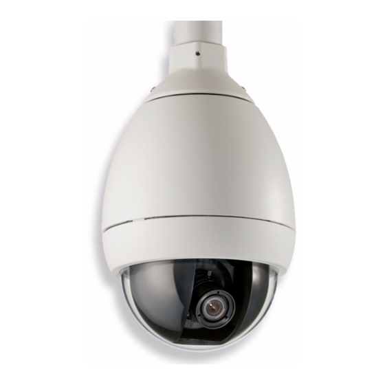
- Page 1 AutoDome Pipe Mount VG4-A-9543 Installation Guide...
-
Page 3: Table Of Contents
2.5.1 Methods for Routing Wires 2.5.2 Wiring the Power Supply Box 2.5.3 Power Supply Box Connections Installing the VG4-A-9543 Pipe Mount Wire the Pipe Interface Board 2.7.1 Wiring for Multiple AutoDomes 2.7.2 Connecting Wires to the Pipe Interface Board Attach Pendant to Pipe and Tighten... - Page 4 Configuring Non-supervised Alarms (inputs 1 through 7) 4.3.1 Configuring a Normally Open Non-supervised Alarm 4.3.2 Configuring a Normally Closed Non-supervised Alarm Alarm Outputs 4.4.1 Configuring a Dry Contact Relay 4.4.2 Configuring an Open Collector Output F.01U.251.410 | 1.0 | 2011.08 Installation Guide Bosch Security Systems, Inc.
-
Page 5: Important Safety Instructions
Unplug the unit during lightning storms or when unused for long periods. Take precautions to protect the unit from power and lightning surges. Adjust only those controls specified in the operating instructions. Bosch Security Systems, Inc. Installation Guide F.01U.251.410 | 1.0 | 2011.08... - Page 6 You can view and print the full version of this Installation Manual with Adobe Acrobat Reader, both provided on the enclosed CD-ROM. This user guide is the intellectual property of Bosch Security Systems; protected by copyright. Contact: www.boschsecurity.com F.01U.251.410 | 1.0 | 2011.08 Installation Guide Bosch Security Systems, Inc.
-
Page 7: Installing The Pipe Mount
Verify that all the parts listed in the product's Parts List below are included. If any items are missing, notify your Bosch Security Systems Sales or Customer Service Representative. The original packing carton is the safest container in which to transport the unit and must be used if returning the unit for service. -
Page 8: Optional Power Supplies
Small straight blade screwdrivers ~ 2.5 mm (0.1 in.) – 3.1 mm (1/8 in.) – Medium straight blade screwdriver – No. 1 and No. 2 Phillips screwdrivers – Socket wrench and 9/16 in. socket – Pipe Wrench F.01U.251.410 | 1.0 | 2011.08 Installation Guide Bosch Security Systems, Inc. -
Page 9: Pre-Installation Check List
Circuit Breaker or Branch Rated Fuses are required as part of the building installation. A readily accessible 2-pole disconnect device with a contact separation of at least 3 mm must be incorporated. Bosch Security Systems, Inc. Installation Guide F.01U.251.410 | 1.0 | 2011.08... - Page 10 Purchase the appropriate mounting hardware to use, depending on the location of the AutoDome and the application. CAUTION! Select a rigid mounting location to prevent excessive vibration to the AutoDome camera. F.01U.251.410 | 1.0 | 2011.08 Installation Guide Bosch Security Systems, Inc.
-
Page 11: Pressurized Environmental Mounting Option
9543N Pipe Mount. CAUTION! DO NOT mount a Pressurized Environmental Housing to the VG4-A-9543 mounting option. This pipe mount contains guide pins that are not compatible with the Pressurized Environmental Housing. Refer to item 1 on the image below: If your pipe mount contains these pins, DO NOT attempt to mount a Pressurized Environmental Housing to this mount. -
Page 12: Mount Power Supply Box
Use 3/4-inch NPS (20-mm) fittings for the holes on the bottom and back of the box. Use 1/2-inch NPS (15-mm) fittings for the side holes. Figure 2.1 Wall Mount Power Supply with Optional Trim Skirt F.01U.251.410 | 1.0 | 2011.08 Installation Guide Bosch Security Systems, Inc. - Page 13 Attach the 3/4 in. (20 mm) watertight pipe fittings (not supplied) to the holes of the Power Supply Box through which you will run the power, video, and control data wires. Bosch Security Systems, Inc. Installation Guide F.01U.251.410 | 1.0 | 2011.08...
-
Page 14: Attach Cover Door
After all wiring is complete, close the cover door and tighten the two (2) captive screws on the cover door to 10-12 N-m (90- 105 in.-lbs) to ensure the Power Supply Box is watertight. F.01U.251.410 | 1.0 | 2011.08 Installation Guide Bosch Security Systems, Inc. -
Page 15: Route Wires And Attach Connectors
Circuit Breaker or Branch Rated Fuses are required as part of the building installation. A readily accessible 2-pole disconnect device with a contact separation of at least 3 mm must be incorporated. Bosch Security Systems, Inc. Installation Guide F.01U.251.410 | 1.0 | 2011.08... -
Page 16: Methods For Routing Wires
5 Coax, UTP Video, or Ethernet Power In Wire (Ethernet for VG5 700 Series only) 2 P101 Connector 6 Control Wire 3 Ground Connection 7 24 VAC Power Out 4 Transformer 8 P107 Connector F.01U.251.410 | 1.0 | 2011.08 Installation Guide Bosch Security Systems, Inc. - Page 17 Heater Power NOTICE! Fiber Optic Models require that the Biphase control wires be routed from the Power Supply Box P106 connector out to the Pipe Interface Board P105 connector. Bosch Security Systems, Inc. Installation Guide F.01U.251.410 | 1.0 | 2011.08...
-
Page 18: Wiring The Power Supply Box
Table 2.1, Page 20. NOTICE! All video, control, and alarm wires either pass through the Power Supply Box or by-pass it and connect directly to the Pipe Interface Board. F.01U.251.410 | 1.0 | 2011.08 Installation Guide Bosch Security Systems, Inc. -
Page 19: Power Supply Box Connections
24 VAC to Dome Control Data and Video In/Out; Interface Board 3/4 in. (20 mm) NPS Fitting WARNING! Fuse replacement by qualified service personnel only. Replace with same type fuse. Bosch Security Systems, Inc. Installation Guide F.01U.251.410 | 1.0 | 2011.08... - Page 20 Earth Heater Heater Dome Plug 24 VAC 24 VAC Ground (24 VAC) (24 VAC) 1. Applicable to VG5 600 and 100 Series AutoDomes only. Table 2.1 Power Box Connections F.01U.251.410 | 1.0 | 2011.08 Installation Guide Bosch Security Systems, Inc.
-
Page 21: Installing The Vg4-A-9543 Pipe Mount
AutoDome Pipe Mount Installing the Pipe Mount | en Installing the VG4-A-9543 Pipe Mount This section details the installation steps for the VG4-A-9543 Pipe Mount. NOTICE! Customer must supply 1-1/2 inch (NPS) pipe threaded on both ends with a minimum length of 5 inches (12.7 cm). - Page 22 WARNING! You must thread the Dome Cap onto the pipe until it is tight. Failure to do so can result in damage or serious injury or death. F.01U.251.410 | 1.0 | 2011.08 Installation Guide Bosch Security Systems, Inc.
-
Page 23: Wire The Pipe Interface Board
Section 3 Cable and Wire Standards, page 31 for cable and wiring recommendations and specifications. AGND OUT 3 OUT 2 OUT 1 Figure 2.6 Pipe Interface Board Connections Bosch Security Systems, Inc. Installation Guide F.01U.251.410 | 1.0 | 2011.08... - Page 24 Dome 24 VAC Heater Power P107 AWG 18-14 2 Heater 24 VAC Heater 24 VAC RJ45 Ethernet or UTP J101 Video (Ethernet for VG5 700 Series only) To AutoDome F.01U.251.410 | 1.0 | 2011.08 Installation Guide Bosch Security Systems, Inc.
-
Page 25: Wiring For Multiple Autodomes
This connection causes video distortion. IP AutoDome: Attach an RJ45 connector plug to the Ethernet cable and connect the plug to its mating connector J101 on the Pipe Interface Board. Bosch Security Systems, Inc. Installation Guide F.01U.251.410 | 1.0 | 2011.08... - Page 26 P103 and P102 on the Pipe Interface Board. WHITE BROWN P102 ORANGE GREEN WHITE BROWN ORANGE P103 GREEN YELLOW BLUE P104 Figure 2.7 Alarm and Relay Connector Plugs F.01U.251.410 | 1.0 | 2011.08 Installation Guide Bosch Security Systems, Inc.
- Page 27 45 for more details on wiring alarms and relays. Note: There is a slot located at the top of the Interface Board to tie the wires to the circuit board with a cable tie. Bosch Security Systems, Inc. Installation Guide F.01U.251.410 | 1.0 | 2011.08...
- Page 28 Be careful not to strip the threads when tightening the Pipe Interface Board retaining screws. Figure 2.8 Pipe Interface Board to Dome Cap Assembly Interface Board Retaining Screws (3) Pendant Mounting Screws (2) F.01U.251.410 | 1.0 | 2011.08 Installation Guide Bosch Security Systems, Inc.
-
Page 29: Attach Pendant To Pipe And Tighten
2a Dome Cap 2b Recessed Hinge Pin 2c Dome Connector Rotate down to engage dome connector Tighten the two (2) mounting screws to a minimum torque of 10-12 N-m (90-105 in.-lbs) Bosch Security Systems, Inc. Installation Guide F.01U.251.410 | 1.0 | 2011.08... - Page 30 Parapet Arm in position. Refer to Figure 2.9, Page 29, for an illustration. CAUTION! Do not over tighten the bolts. The maximum torque is 34 N-m (25 ft-lb). F.01U.251.410 | 1.0 | 2011.08 Installation Guide Bosch Security Systems, Inc.
-
Page 31: Cable And Wire Standards
AutoDome 700, Outdoor 1. Standard heater module. Add Add 16 W if using VG4-SHTR-XT kit. 2. Standard heater module. The VG4-SHTR-XT kit is not applicable to VG5 700 Series AutoDomes. Bosch Security Systems, Inc. Installation Guide F.01U.251.410 | 1.0 | 2011.08... -
Page 32: Video And Control Cables
Bilinx control data can also be sent over the same cable. Bilinx is a Bosch 2-way communication protocol that allows remote control, configuration, and updates over a video coax cable. Bilinx is available on all VG5 100 and 600 Series AutoDomes. -
Page 33: Using Utp To Transmit Video And Control
Bilinx control data can also be sent over the same two video wires (1 & 2). Bilinx is a Bosch 2-way communication protocol that allows remote control, configuration and updates over a passive UTP cable. -
Page 34: Using Ethernet To Transmit Video And Control
Maximum Distance 4 km (2.5 miles) Minimum Bandwidth 20 MHz (Video - 850 nm / Control - 1300 nm) Requirement Bosch LTC 4629 Fiber Receiver at controller end of system Terminal Connector Singlemode Fiber Type 9/125 µm, low loss single glass fiber... -
Page 35: Using A Fiber Optic Ethernet Media Converter To Transmit Video And Control
3.4.1 Controlling the AutoDome via Biphase (Shielded 2-wire, half-duplex, multi-drop, 5000 ft. cable limit) Biphase is the standard Bosch protocol used to send Pan/Tilt/ Zoom control over 2-wire shielded twisted pair (STP) terminated with a 100 Ω terminal resistor. The AutoDome has a 100 Ω termination resistor between the Biphase C+ and C- terminals. - Page 36 2 C+ (Biphase) Head End Biphase 3 Earth Ground 9 P105/P106 Connector in Power Supply 4 RxD 10 C- (Biphase) 5 TxD 11 C+ (Biphase) 6 Signal Ground 12 Shield F.01U.251.410 | 1.0 | 2011.08 Installation Guide Bosch Security Systems, Inc.
-
Page 37: Controlling The Autodome Via The Rs232 Protocol
NOTICE! After making the wire connections for RS232 operation, reposition the slide switch located on the CPU Module to the camera head inward and away from the LEDs. Bosch Security Systems, Inc. Installation Guide F.01U.251.410 | 1.0 | 2011.08... - Page 38 Figure 3.5 Position of CPU Switch for RS232 Operation (camera module not shown for clarity) Switch Location LEDs RS232 CPU Module Note: To access the CPU switch you must remove the bubble from the pendant housing. F.01U.251.410 | 1.0 | 2011.08 Installation Guide Bosch Security Systems, Inc.
-
Page 39: Controlling The Autodome Via The Rs485 Protocol
LEDs (default). CAUTION! Bosch recommends that multiple RS485 connections be arranged as a connected series of point-to-point (multi- dropped) nodes, as a line or as a bus. It is not recommended to arrange RS485 connections as a star, ring, or as a multiple- connected network. - Page 40 Figure 3.7 Position of CPU Switch for RS485 Operation (camera module not shown for clarity) Switch Location LEDs RS485 CPU Module Note: To access the CPU switch you must remove the bubble from the pendant housing. F.01U.251.410 | 1.0 | 2011.08 Installation Guide Bosch Security Systems, Inc.
-
Page 41: Fiber Optic Module With An Rs232/Rs422 Controller
(RxD) wire enough to be able to connect these wires back into the P106 connector. Connect the blue (ground) wire to the C- pin on the P106 connector. Bosch Security Systems, Inc. Installation Guide F.01U.251.410 | 1.0 | 2011.08... - Page 42 Switch Location LEDs Move Switch to the left for RS232 Operation CPU Module 11. Return the bubble to the AutoDome housing. 12. Return power to the power supply box. F.01U.251.410 | 1.0 | 2011.08 Installation Guide Bosch Security Systems, Inc.
-
Page 43: Audio Cables
22 AWG to Biphase connector (P105/P106) Shield Bare copper braid: 95% coverage Center conductor Stranded bare copper NOTICE! Separate the audio cables from the AC power lines to avoid noise. Bosch Security Systems, Inc. Installation Guide F.01U.251.410 | 1.0 | 2011.08... - Page 44 C+ (Biphase) P105/P106 Connector Earth Ground Audio Out Signal Ground NOTICE! Refer to the VG5 700 Series AutoDome User Manual for configuring and using audio over an IP Ethernet network. F.01U.251.410 | 1.0 | 2011.08 Installation Guide Bosch Security Systems, Inc.
-
Page 45: Alarms And Relay Connections
Only Alarms 1 and 2 (pins 5 or 6) can be configured for supervision. Once a supervised alarm is programmed it does not need to be enabled to indicate a tamper condition. Bosch Security Systems, Inc. Installation Guide F.01U.251.410 | 1.0 | 2011.08... -
Page 46: Configuring A Normally Open Supervised Alarm
(pin 7) at the AutoDome. 2.2K Figure 4.2 N.C.S. - Normally Closed Supervised Connections Dry Contact Dome Connector Alarm 1 or 2 only (Pin 5 or 6) Ground (Pin 7) F.01U.251.410 | 1.0 | 2011.08 Installation Guide Bosch Security Systems, Inc. -
Page 47: Configuring Non-Supervised Alarms (Inputs 1 Through 7)
From the AutoDome main menu select Alarm Setup>Inputs Setup, and set Alarm Input # to N.O. See the table below for contact and condition details. AutoDome Programmed N.O. Circuit Alarm Indication Open Normal Closed Alarm Bosch Security Systems, Inc. Installation Guide F.01U.251.410 | 1.0 | 2011.08... -
Page 48: Configuring A Normally Closed Non-Supervised Alarm
2 A @ 30 DC. Connect the appropriate stripped wire to the AutoDome COM connector. Connect the appropriate stripped wire to the N.O. or N.C. connector, depending on your requirement. F.01U.251.410 | 1.0 | 2011.08 Installation Guide Bosch Security Systems, Inc. -
Page 49: Configuring An Open Collector Output
@ 150 ma. Connect the appropriate stripped wire to the open connector (1, 2, or 3) of the transistor. Connect the appropriate stripped wire to the ground (GND) connector. Bosch Security Systems, Inc. Installation Guide F.01U.251.410 | 1.0 | 2011.08... - Page 50 | Alarms and Relay Connections AutoDome Pipe Mount F.01U.251.410 | 1.0 | 2011.08 Installation Guide Bosch Security Systems, Inc.
- Page 52 Bosch Security Systems, Inc. 850 Greenfield Road Lancaster, PA 17601 U.S.A. www.boschsecurity.com © Bosch Security Systems, Inc., 2011...