Table of Contents
Advertisement
Quick Links
Operation &
Maintenance Manual
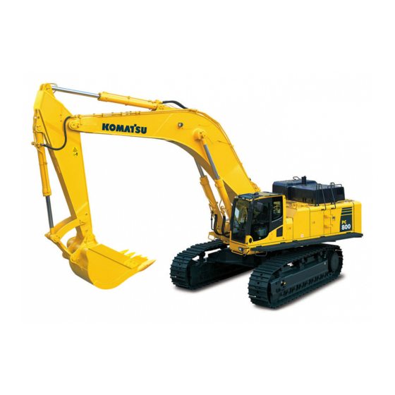
PC800
PC800LC
HYDRAULIC EXCAVATOR
SERIAL NUMBER
PC800-8
PC800LC-8
WARNING
Unsafe use of this machine may cause serious injury or
death. Operators and maintenance personnel must read
this manual before operating or maintaining this
machine. This manual should be kept inside the cab for
reference and periodically reviewed by all personel who
will come into contact with the machine.
-8
- 50001
and up
- 50001
and up
-8
UEAM005400
Advertisement
Table of Contents

Related Manuals for Komatsu PC800-8


Summary of Contents for Komatsu PC800-8
- Page 1 Operation & UEAM005400 Maintenance Manual PC800 PC800LC HYDRAULIC EXCAVATOR SERIAL NUMBER PC800-8 - 50001 and up PC800LC-8 - 50001 and up WARNING Unsafe use of this machine may cause serious injury or death. Operators and maintenance personnel must read this manual before operating or maintaining this machine.
- Page 3 FOREWORD...
- Page 4 Keep this manual at the storage location for the Operation and Maintenance Manual given below so that all personnel involved in working on the machine can consult it periodically. In case this manual should be lost or damaged, immediately contact Komatsu or your Komatsu distributor to obtain a new copy.
-
Page 5: Foreword
FOREWORD SAFETY INFORMATION SAFETY INFORMATION To enable you to use this machine safely, safety precautions and labels are given in this manual and affixed to the machine to give explanations of situations involving potential hazards and of the methods of avoiding such situa- tions. - Page 6 Continuing improvements in the design of this machine can lead to changes in detail which may not be reflected in this manual. Consult Komatsu or your Komatsu distributor for the latest available information of your machine or for questions regarding information in this manual.
-
Page 7: Noise Emission Levels
FOREWORD SAFETY INFORMATION Noise emission levels Two labels indicating the machine noise level are affixed on the machine. q Sound pressure level at the operator’s station, measured according to ISO6396 (Dynamic test method, simulated working cycle). q Sound power level emitted by the machine, measured according to ISO 6395 (Dynamic test method, simulated working cycle). -
Page 8: Vibration Levels
FOREWORD SAFETY INFORMATION Vibration levels When used for its intended purpose, levels of vibration for the earth-moving machine transmitted from the operator’s seat are lower than or equal to the tested vibrations for the relative machinery class in compliance with ISO 7096. The actual acceleration value for the hands and arms is less than or equal to 2.5 m/s². - Page 9 FOREWORD SAFETY INFORMATION 6. Adjust the machine speed and travel path to minimize the vibration level q When pushing with bucket or blade, avoid sudden loading; load gradually q Drive around obstacles and rough terrain conditions q Slow down when it is necessary to go over rough ter- rain q Make the curve radius of traveling path as large as possible...
-
Page 10: Breaking-In The New Machine
BREAKING-IN THE NEW MACHINE NOTICE Your Komatsu machine has been thoroughly adjusted and tested before shipment from the factory. How- ever, operating the machine under full load before breaking the machine in can adversely affect the perfor- mance and shorten the machine life. -
Page 11: Introduction
FOREWORD INTRODUCTION INTRODUCTION This Komatsu machine is designed to be used mainly for the following work: q Digging work q Leveling work q Ditching work q Loading work q Demolition work See the section “RECOMMENDED APPLICATIONS (3-121)“ for further details. -
Page 12: Visibility From Operator's Seat
FOREWORD INTRODUCTION VISIBILITY FROM OPERATOR'S SEAT The visibility standards (ISO 5006) for this machine require a view shown in the diagram below. PROXIMITY VISIBILITY The visibility of this machine in the area 1 m from the outside surface of the machine at a height of 1.5 m is shown in the diagram below. -
Page 13: Product Information
FOREWORD PRODUCT INFORMATION PRODUCT INFORMATION When requesting service or ordering replacement parts, please inform your Komatsu distributor of the following items. PRODUCT IDENTIFICATION NUMBER (PIN)/MACHINE SERIAL NO. PLATE On the bottom right of the operator's cab The design of the nameplate differs according to the territory. -
Page 14: Service Meter Location
SERVICE METER LOCATION On top of the machine monitor YOUR MACHINE SERIAL NUMBERS AND DISTRIBUTOR Machine serial No. Engine serial No. Product Identification Number Manufacturers name: KOMATSU UK Ltd. Address: Durham Road Birtley Chester-Le street County Durham DH32QX United Kingdom... -
Page 15: Machine Serial Plate
MANUFACTURING YEAR MODEL SERIAL MODEL SERIAL No. MANUFACT. YEAR MASS WEIGHT ENGINE POWER ENGINE POWER Product Identification Number PRODUCT IDENTIFICATION Manufactured by Komatsu UK Ltd. MANUFACTURER NUMBER for Komatsu Ltd.,Tokyo,Japan MANUFACTURER 205-00-K1291 Komatsu UK Ltd, Birtley, Co Durham, United Kingdom 1-13... - Page 16 FOREWORD PRODUCT INFORMATION 1-14...
-
Page 17: Table Of Contents
CONTENTS CONTENTS FOREWORD FOREWORD................................. 1-2 SAFETY INFORMATION............................1-3 Noise emission levels ..........................1-5 Vibration levels............................1-6 GUIDE TO REDUCE VIBRATION LEVELS ON MACHINE .............. 1-6 BREAKING-IN THE NEW MACHINE ......................1-8 INTRODUCTION..............................1-9 DIRECTIONS OF MACHINE ........................1-9 VISIBILITY FROM OPERATOR'S SEAT....................1-10 PROXIMITY VISIBILITY ........................ - Page 18 CONTENTS OPERATION MACHINE VIEW ILLUSTRATIONS ........................3-2 OVERALL MACHINE VIEW........................3-2 CONTROLS AND GAUGES ........................3-3 DETAILED CONTROLS AND GAUGES......................3-5 MONITORING SYSTEM ..........................3-5 BASIC OPERATION OF MACHINE MONITOR ................3-6 EMERGENCY MONITORS ....................... 3-9 CAUTION MONITORS ........................3-11 BASIC CHECK MONITORS ......................
- Page 19 CONTENTS MACHINE OPERATIONS AND CONTROLS..................... 3-76 BEFORE STARTING ENGINE ......................... 3-76 WALK-AROUND CHECKS......................3-76 CHECKS BEFORE STARTING....................... 3-77 ADJUSTMENT..........................3-85 SEAT BELT ............................. 3-88 OPERATIONS BEFORE STARTING ENGINE ................3-89 STARTING ENGINE ..........................3-92 AFTER STARTING ENGINE ........................3-95 ENGINE WARM UP......................... 3-95 HYDRAULIC EQUIPMENT WARM UP ...................
- Page 20 OIL ..............................4-4 FUEL..............................4-5 COOLANT AND WATER FOR DILUTION..................4-5 GREASE ............................4-6 CARRYING OUT KOWA (KOMATSU OIL WEAR ANALYSIS) ............4-6 STORING OIL AND FUEL ......................... 4-7 FILTERS ............................4-7 ELECTRIC SYSTEM MAINTENANCE ....................... 4-8 EXPLANATION OF LUBRICATION CHART DECAL ................. q-9...
- Page 21 CONTENTS WEAR PARTS ..............................4-11 WEAR PARTS LIST..........................4-11 RECOMMENDED FUEL, COOLANT, AND LUBRICANT ................. 4-12 RECOMMENDED BRANDS, RECOMMENDED QUALITY FOR PRODUCTS OTHER THAN KOMATSU GENUINE OIL............................4-14 TIGHTENING TORQUE SPECIFICATIONS ...................... 4-15 TIGHTENING TORQUE LIST........................4-15 SAFETY CRITICAL PARTS ..........................4-16 SAFETY CRITICAL PARTS LIST ......................
- Page 22 CONTENTS CLEAN FRESH/RECIRC AIR FILTERS OF AIR CONDITIONER (ONLY FOR MACHINES EQUIPPED WITH AIR CONDITIONER) ......................4-53 REPLACE PILOT FILTER ....................... 4-54 CLEAN STRAINER OF COUPLING LUBRICATING OIL FILTER........... 4-55 REPLACE DRAIN FILTER CARTRIDGE ..................4-55 CHANGE OIL IN ENGINE OIL PAN, REPLACE ENGINE OIL FILTER CARTRIDGE ....4-56 EVERY 1000 HOURS MAINTENANCE....................
- Page 23 CONTENTS ATTACHMENTS AND OPTIONS GENERAL PRECAUTIONS FOR SAFETY......................6-2 PRECAUTIONS WHEN SELECTING......................6-2 READ THE INSTRUCTION MANUAL THOROUGHLY................6-2 PRECAUTIONS WHEN REMOVING OR INSTALLING ................6-2 PRECAUTIONS WHEN USING........................6-3 ATTACHMENT GUIDE............................6-4 COMBINATIONS OF WORK EQUIPMENT....................6-5 WORKING RANGE DIAGRAM......................6-6 TRACK SHOES SELECTION........................
- Page 24 CONTENTS 1-22...
-
Page 25: Safety
SAFETY WARNING Please read and make sure that you fully understand the precautions discribed in this manual and the safety labels on the machine. When operating or servicing the machine, always follow these precaustions strictly. -
Page 26: Safety Information
SAFETY SAFETY INFORMATION SAFETY INFORMATION SAFETY LABELS..............................2-42 Location of safety labels..........................2-52 Safety labels..............................2-62 SAFETY INFORMATION Safety rules ..............................2-132 If problems are found ..........................2-132 Working wear and personal protective items ..................... 2-132 Fire extinguisher and first aid kit ........................ 2-132 Safety equipment ............................ - Page 27 SAFETY SAFETY INFORMATION Starting engine with booster cables ....................2-312 TOWING ..............................2-312 Safety rules for towing ........................2-312 LIFTING OBJECTS WITH BUCKET......................2-322 Safety rules for lifting objects ......................2-322 SAFETY MAINTENANCE INFORMATION....................... 2-332 Warning Tag .............................. 2-332 Keep Work Place Clean and Tidy ......................2-332 Appoint Leader when Working with Others....................
-
Page 28: Safety Labels
If the labels are damaged, lost, or cannot be read properly, replace them with new ones. For details of the part numbers for the labels, see this manual or the actual label, and place an order with Komatsu distributor. -
Page 29: Location Of Safety Labels
SAFETY SAFETY LABELS LOCATION OF SAFETY LABELS... -
Page 30: Safety Labels
Read the manual and labels before operation and mainte- nance. Follow instructions and warnings in manual and in labels on machine. (1) Keep the manual in machine cab near operator. If this manual is lost, please contact your Komatsu distributor for a replacement. - Page 31 SAFETY SAFETY LABELS (2) Always apply lock when leaving operator’s seat. (3) WARNING - No passengers No passengers allowed to ride on machine while it is moving (4) WARNING - DANGER OF FALLING OBJECTS Do not operate where a danger of falling objects exists. Consult your dealer for fitting of FOPS protection...
- Page 32 SAFETY SAFETY LABELS (5) HAZARDOUS - Voltage hazard Serious injury or death can occur if machine or attachments are not kept safe distance away from electric lines (6) Control levers operational function diagram. (7) Caution when stowing front window (09803-A0481) q Sign indicates a hazard from falling window.
- Page 33 SAFETY SAFETY LABELS (8) Caution for high-temperature coolant and hydraulic oil (09653-A0481) q Never remove the cap when the engine is at operating (high) temperature. Steam or high temperature oil blowing up from the radiator or hydraulic tank, will cause personal injury and/or burns.
- Page 34 SAFETY SAFETY LABELS (11) Caution when handling cable (09808-A0881) q Sign indicates an electric hazard from handling the cable. q Read manual for safe and proper handling. (12) Stopping rotation for inspection and maintenance (09667-A0481) q Sign indicates a hazard of rotating parts, such as belt. q Turn off before inspection and maintenance.
- Page 35 SAFETY SAFETY LABELS (15) Caution against falling (09805-C0481) q Sign indicates a hazard of falling. q Do not stand on this place here!. (16) Prohibited to enter swing radius (09133-A3281) q There is danger of getting caught when upper structure swings.
- Page 36 SAFETY SAFETY LABELS (18) Prohibition of jump start (09842-A0481) q Start the engine only after sitting down in the operator’s seat. q Do not attempt to start the engine by short-circuiting the engine starting circuit. Such an act may cause a serious bodily injury or fire.
-
Page 37: Safety Information
SAFETY SAFETY INFORMATION SAFETY INFORMATION SAFETY RULES q Only trained and authorized personnel can operate and maintain the machine. q Follow all safety rules, precautions and instructions when operating or performing maintenance on the machine. q If you are under the influence of alcohol or medication, your ability to safely operate or repair your machine may be severly impaired putting yourself and everyone else on your jobsite in danger. -
Page 38: Safety Equipment
SAFETY SAFETY INFORMATION SAFETY EQUIPMENT q Be sure that all guards and covers are in their proper position. Have guards and covers repaired immediately if they are damaged. q Understand the method of use of safety features and use them properly. q Never remove any safety features. -
Page 39: Handrails And Steps
SAFETY SAFETY INFORMATION q When leaving the machine, always lower the work equip- ment completely to the ground, set lock lever (1) securely to the LOCK position (L), then stop the engine. Use the key to lock all the equipment. Always remove the key, take it with you, and keep it in the specified place. -
Page 40: Mounting And Dismounting
SAFETY SAFETY INFORMATION MOUNTING AND DISMOUNTING q Never jump on or off the machine. Never get on or off a moving machine. q If the machine starts to move when there is no operator on the machine, do not jump on to the machine and try to stop it. -
Page 41: Fire Prevention And Explosion Prevention
SAFETY SAFETY INFORMATION FIRE PREVENTION AND EXPLOSION PREVENTION q Fire caused by fuel or oil Fuel, oil, antifreeze, and window washer liquid are particu- larly flammable and can be hazardous. To prevent fire, always observe the following: q Do not smoke or use any flame near fuel or oil. q Stop the engine before refueling. -
Page 42: Action If Fire Occurs
The above recommendations assume that the conditions are for standard operations, but it may be necessary to add additional guards according to the operating conditions on the jobsite. Always contact your Komatsu distributor for advice. ATTACHMENT INSTALLATION q When installing optional parts or attachments, there may be problems with safety or legal restrictions. There- fore contact your Komatsu distributor for advice. -
Page 43: Attachment Combinations
UNAUTHORIZED MODIFICATIONS If this machine is modified without permission from Komatsu, there is danger that problems may occur with safety and that this may lead to serious personal injury. Modifications may have an adverse effect on items such as machine strength and visibility. -
Page 44: Distance To High Voltage Cables
SAFETY SAFETY INFORMATION DISTANCE TO HIGH VOLTAGE CABLES Do not travel or operate the machine near electric cables. There is a hazard of electric shock, which may cause serious injury or property damage. On jobsites where the machine may go close to electric cables, always do as follows. q Before starting work near electric cables, inform the local power company of the work to be performed, and ask them to take the necessary action. -
Page 45: Ventilation For Enclosed Area
Do not allow other persons to approach during the operation. q Always observe the rules and regulations for the work site and environmental standards. This machine does not use asbestos, but there is a danger that imitation parts may contain asbestos, so always use genuine Komatsu parts. 2-21... -
Page 46: Safety Machine Operation
SAFETY SAFETY MACHINE OPERATION SAFETY MACHINE OPERATION STARTING ENGINE If there is a warning tag hanging from the work equipment con- trol lever, do not start the engine or touch the levers . CHECKS BEFORE STARTING ENGINE Carry out the following checks before starting the engine at the beginning of the day's work. q Remove all dirt from the surface of the window glass to ensure a good view. -
Page 47: Operation
SAFETY SAFETY MACHINE OPERATION STARTING ENGINE IN COLD WEATHER q Carry out the warming-up operation thoroughly. If the machine is not thoroughly warmed up before the control levers are operated, the reaction of the machine will be slow, and this may lead to unexpected accidents. q If the battery electrolyte is frozen, do not charge the battery or start the engine with a different power source. -
Page 48: Safety Rules For Traveling
SAFETY SAFETY MACHINE OPERATION q Before traveling, set the machine so that sprocket (1) is behind the operator's seat. If sprocket (1) is in front of the operator's cab, the machine moves in the opposite direction from the operation of the lever (front and rear travel is reversed, left and right steer- ing is reversed). -
Page 49: Traveling On Slopes
SAFETY SAFETY MACHINE OPERATION TRAVELING ON SLOPES To prevent the machine from tipping over or slipping to the side, always do as follows. q Keep the work equipment approx. 20 to 30 cm above the ground. In case of emergency, lower the work equipment to the ground immediately to help stop the machine. -
Page 50: Operations On Slopes
SAFETY SAFETY MACHINE OPERATION OPERATIONS ON SLOPES q When working on slopes, there is a hazard that the machine may lose its balance and turn over when the swing or work equipment are operated. This may lead to serious injury or property damage, so always provide a stable place when carrying out these operations, and operate carefully. - Page 51 SAFETY SAFETY MACHINE OPERATION q Do not carry out demolition work under the machine. There is a hazard that the machine may become unstable and tip over. q When working on or from the top of buildings or other structures, check the strength and the structure before starting operations.
-
Page 52: Operations On Snow
SAFETY SAFETY MACHINE OPERATION OPERATIONS ON SNOW q Snow-covered or frozen surfaces are slippery, so be extremely careful when traveling or operating the machine, and do not operate the levers suddenly. Even a slight slope may cause the machine to slip, so be particularly careful when working on slopes. -
Page 53: Transportation
SAFETY MACHINE OPERATION TRANSPORTATION The machine can be divided into parts for transportation, so when transportating the machine, please contact your Komatsu distributor to have the work carried out. LOADING AND UNLOADING When loading or unloading the machine, mistaken operation may bring the hazard of the machine tipping over or falling, so particular care is necessary. -
Page 54: Battery
SAFETY SAFETY MACHINE OPERATION BATTERY BATTERY HAZARD PREVENTION Battery electrolyte contains sulphuric acid, and batteries generate flammable hydrogen gas, which may explode. Mistaken handling can lead to serious injury or fire. For this reason, always observe the following precautions. q Do not use or charge the battery if the battery electrolyte level is below the LOWER LEVEL line. This may cause an explosion. -
Page 55: Towing
SAFETY SAFETY MACHINE OPERATION STARTING ENGINE WITH BOOSTER CABLES If any mistake is made in the method of connecting the booster cables, it may cause the battery to explode, so always do as follows. q When starting with a booster cable, carry out the starting operation with two workers (one worker sitting in the opera- tor's seat and the other working with the battery). -
Page 56: Lifting Objects With Bucket
SAFETY SAFETY MACHINE OPERATION LIFTING OBJECTS WITH BUCKET SAFETY RULES FOR LIFTING OBJECTS q Do not carry out lifting work on slopes, soft ground, or other places where the machine is not stable. q Use wire rope that conforms to the specified standard. q Always observe the specified lifting load strictly. -
Page 57: Safety Maintenance Information
SAFETY SAFETY MAINTENANCE INFORMATION SAFETY MAINTENANCE INFORMATION WARNING TAG q Always attach the “DO NOT OPERATE“ warning tag to the work equipment control lever in the operator's cab to alert others that you are performing service or maintenance on the machine. Attach additional warning tags around the machine if necessary. -
Page 58: Stop Engine Before Carrying Out Maintenance
SAFETY SAFETY MAINTENANCE INFORMATION STOP ENGINE BEFORE CARRYING OUT MAINTENANCE q Stop the machine on firm, level ground. q Select a place where there is no hazard of falling rocks or landslides, or of flooding if the land is low. q Lower the work equipment completely to the ground and stop the engine. -
Page 59: Proper Tools
Do not hit or roll the accumulator, or subject it to any impact. q When disposing of the accumulator, the gas must be released. Please contact your Komatsu distributor to have this work performed. PERSONNEL Only authorized personnel can service and repair the machine. Do not allow unauthorized personnel into the area. -
Page 60: Attachments
SAFETY SAFETY MAINTENANCE INFORMATION ATTACHMENTS q Appoint a leader before starting removal or installation operations for attachments. q Place attachments that have been removed from the machine in a stable condition so that they do not fall. And take steps to prevent unauthorized persons from entering the storage area. -
Page 61: Removing Battery Terminals
If it is disassembled by mistake, the spring will fly out and cause serious injury. When it becomes necessary to disassemble it, ask your Komatsu distributor to do the work. SAFETY RULES FOR HIGH-PRESSURE OIL The hydraulic system is always under internal pressure. -
Page 62: Precaution For High Fuel Pressure
If any loose bolts are found, stop work and tighten to the specified torque. If any damaged hoses are found, stop operations immediately and contact your Komatsu distributor. Replace the hose if any of the following problems are found. -
Page 63: Waste Materials
SAFETY SAFETY MAINTENANCE INFORMATION WASTE MATERIALS To prevent pollution, pay careful attention to the method of disposing of waste materials. q Always put oil drained from your machine in containers. Never drain oil directly onto the ground or dump into the sewage system, rivers, the sea, or lakes. - Page 64 SAFETY SAFETY MAINTENANCE INFORMATION 2-40...
- Page 65 OPERATION WARNING Please read and make sure that you understand the SAFETY section before reading this section.
-
Page 66: Operation
OPERATION MACHINE VIEW ILLUSTRATIONS MACHINE VIEW ILLUSTRATIONS OVERALL MACHINE VIEW Bucket Sprocket Bucket link Track frame Bucket cylinder (10) Track shoe (11) Idler Arm cylinder (12) OPG (Operator Protection Guard) This is an option for the PC800-8. Boom Boom cylinder... -
Page 67: Controls And Gauges
OPERATION MACHINE VIEW ILLUSTRATIONS CONTROLS AND GAUGES (11) Horn switch Lower wiper switch (Fixed front window cab specification) (12) Right work equipment control lever (if equipped) (13) Starting switch Rotating lamp switch (if equipped) (14) Fuel control dial (15) Lamp switch Large capacity airflow air conditioner blower switch (if equipped) (16) Swing lock switch... - Page 68 OPERATION MACHINE VIEW ILLUSTRATIONS Machine monitors User mode adjustment switch (16) Fuel gauge Working mode selection switch (17) Fuel level monitor Wiper monitor (18) Auto-deceleration monitor Engine pre-heating monitor (19) Display control switch Swing lock monitor (20) Input control switch Engine water temperature monitor (21) Window washer switch Engine oil pressure monitor...
-
Page 69: Detailed Controls And Gauges
OPERATION DETAILED CONTROLS AND GAUGES DETAILED CONTROLS AND GAUGES The following is an explanation of devices needed for operating the machine. To perform suitable operations correctly and safely, it is important to completely understand methods of operating the equipment, and the meanings of the displays. MONITORING SYSTEM AA: Screen with all lamps lighted up BB: Screen for normal... -
Page 70: Basic Operation Of Machine Monitor
OPERATION DETAILED CONTROLS AND GAUGES Basic Operation of Machine Monitor If There Is Abnormality When Starting Engine q If there is any abnormality when starting the engine, the check before starting screen DD changes to the main- tenance interval warning screen CC, warning screen FF, or error screen EE. q After displaying the check before starting screen DD for 2 seconds, the screen changes to the maintenance interval warning screen CC. - Page 71 OPERATION DETAILED CONTROLS AND GAUGES If Any Abnormality Occurs During Operation q If any abnormality occurs during operation, the normal screen BB changes to warning screen FF-(1) or the error screen EE. q After displaying warning screen FF-(1) for 2 seconds, the screen automatically changes to warning screen FF- (2).
- Page 72 OPERATION DETAILED CONTROLS AND GAUGES REMARK The colors lighting up the monitors related to the emergency stop items, caution items, and basic check items are as follows. Color when monitor lights up Type of monitor When At low When normal abnormal temperature Engine coolant temperature monitor...
-
Page 73: Emergency Monitors
OPERATION DETAILED CONTROLS AND GAUGES Emergency Monitors CAUTION If the monitor lights up red, stop the engine immediately or run at low idle, check applicable location, then perform necessary actions. These items should be observed while the engine is running. If there is a problem, the monitor for the abnormal location lights up red and buzzer sounds, perform action immediately. - Page 74 OPERATION DETAILED CONTROLS AND GAUGES Hydraulic Oil Temperature Monitor Monitor (2) warns operator that the hydraulic oil temperature has risen. If monitor lights up red during operations, run engine at low idle or stop the engine and wait until the oil temperature goes down and monitor (2) changes to green.
-
Page 75: Caution Monitors
OPERATION DETAILED CONTROLS AND GAUGES Caution Monitors CAUTION If the warning monitor lights up red, stop operations as soon as possible and perform inspection and maintenance of the applicable location. If the warning is ignored, it may lead to failure. These are items that should be observed while the engine is running. - Page 76 OPERATION DETAILED CONTROLS AND GAUGES Fuel Level Monitor Monitor (2) lights up to warn the operator the fuel level in the tank is low. If the remaining amount of fuel goes down to 125 liters, the light changes from green to red, so add fuel as soon as possible. Air Cleaner Clogging Monitor Monitor (3) warns the operator of a clogged air cleaner.
-
Page 77: Basic Check Monitors
OPERATION DETAILED CONTROLS AND GAUGES Basic Check Monitors CAUTION These monitors DO NOT ensure that the machine is in good condition. When performing checks before starting (daily checks), do not simply rely on the monitors. Always dismount the machine and check each item directly. - Page 78 For details of the method of checking the maintenance interval, see “Maintenance Switch (3-24)“ in the Detailed controls and gauges. If it is desired to change the maintenance interval settings, have your Komatsu distributor change the interval settings. 3-14...
-
Page 79: Meter Display Portion
OPERATION DETAILED CONTROLS AND GAUGES Meter Display Portion Pilot display Gauges and Meter Engine pre-heating monitor Engine coolant temperature gauge Swing lock monitor Fuel gauge Wiper monitor Hydraulic oil temperature gauge Auto-deceleration monitor (10) Service meter Working mode monitor Travel speed monitor Pilot Display When starting switch is ON, the pilot display lights up when display items are functioning. - Page 80 OPERATION DETAILED CONTROLS AND GAUGES Swing Lock Monitor Monitor (2) informs the operator that the swing lock is being actuated. Actuated: Lights up When the swing lock switch is turned ON (ACTUATED), the monitor lamp lights up. This monitor flashes when the swing holding brake release switch is turned on.
- Page 81 OPERATION DETAILED CONTROLS AND GAUGES Travel Speed Monitor Monitor (6) displays set mode for the travel speed. The monitor display when the travel speed selector switch is operated, as follows. Lo: Low speed Hi: High speed Gauges and Meter Engine Coolant Temperature Gauge This meter (7) indicates the engine cooling water temperature.
- Page 82 OPERATION DETAILED CONTROLS AND GAUGES Fuel Gauge Meter (8) displays the level of fuel in the fuel tank. During operations, the indicator should be in the black range. If indicator enters red range (A) during operations, there is less than 125 liters of fuel remaining in the tank, check and add fuel. (A) - (B): Red range (A) - (C): Black range REMARK...
-
Page 83: Monitor Switches Portion
OPERATION DETAILED CONTROLS AND GAUGES Service Meter This monitor (10) displays the total time that the machine has been operated. Use the time display to set the maintenance interval. When the starting switch is ON, the service meter advances even if the machine is not moving. - Page 84 If it is desired to have the working mode set to start automatically in E, L, or B mode (default option setting), have your Komatsu distributor change the setting. REMARK When the mode selector switch is pressed, the mode is dis- played in the center of monitor display portion (GG), and the screen returns to normal screen (BB) after 2 seconds.
- Page 85 OPERATION DETAILED CONTROLS AND GAUGES q Auto-deceleration function When the auto-deceleration function is ON, if the work equipment and travel levers are returned to the N posi- tion, the engine speed will drop after 4 seconds from the operating speed to idling speed. This makes it possible to reduce fuel consumption.
- Page 86 OPERATION DETAILED CONTROLS AND GAUGES REMARK Each time that the travel speed selector switch is operated, the mode is displayed in the center of display portion (GG), and the screen returns to normal screen (BB) after 2 seconds. Wiper Switch Switch (4) operates the wiper for the front glass.
- Page 87 OPERATION DETAILED CONTROLS AND GAUGES REMARK Each time that the wiper switch is operated, the mode is dis- played in the center of display portion (GG). The screen returns to normal screen (BB) after 2 seconds. Window Washer Switch This switch (5) is kept continuously pressed, window washer fluid is sprayed out on the front glass.
- Page 88 OPERATION DETAILED CONTROLS AND GAUGES Maintenance Switch q Switch (6) is used to check the time remaining until mainte- nance. q When switch (6) is pressed, screen on the monitor display changes to the maintenance screen, as shown in diagram on the right.
- Page 89 Replace hydraulic oil pilot filter Replace hydraulic oil drain filter If it is desired to change settings for the maintenance interval, have your Komatsu distributor change the settings. q The method of checking time remaining until maintenance is as follows: 1.
- Page 90 OPERATION DETAILED CONTROLS AND GAUGES 3. Check the time remaining until maintenance. (a): Time remaining until maintenance (b): Default setting for maintenance interval When only checking the time remaining until maintenance, press back switch (8) twice. The screen will return to the normal operation monitor screen.
- Page 91 OPERATION DETAILED CONTROLS AND GAUGES 2. Fan reverse rotation means that the air from the fan blows to the outside of the machine. This can be used when cleaning to remove insects or dirt stuck to the net. Check first that there is no flammable or burning material in the surrounding area that will be sucked in, then operate the switch to rotate the fan in reverse.
- Page 92 OPERATION DETAILED CONTROLS AND GAUGES 7. If any abnormality occurs when the fan is rotating in reverse, a warning monitor is displayed as shown in the diagram on the right. If the warning monitor is displayed, see “MONITORING SYSTEM (3-5)“ and follow the instruc- tions.
- Page 93 OPERATION DETAILED CONTROLS AND GAUGES REMARK In some cases, the screen in Step 1 may switch to the screen on the right (red display) without switching to the screen in Step 4, and the fan may not rotate in reverse. This is designed to protect the equipment and to prevent the fan from rotating in reverse depending on the water temperature and hydraulic oil temperature.
- Page 94 OPERATION DETAILED CONTROLS AND GAUGES 4. Press input confirmation switch (11). The relationship between fuel consumption and production is as follows. E0: Default set value (maximum emphasis on production, not on fuel consumption) E1: Economy adjustment 1 (emphasis on production) E2: Economy adjustment 2 (emphasis on fuel consump- tion) E3: Economy adjustment 3 (maximum emphasis on fuel...
- Page 95 OPERATION DETAILED CONTROLS AND GAUGES Input Confirmation Switch Press switch (11) to confirm selected mode when in the mainte- nance mode, brightness/contrast adjustment mode, or select mode. Liquid Crystal Monitor Adjustment Switch Press switch (12) to adjust the brightness or contrast of the dis- play monitor.
- Page 96 OPERATION DETAILED CONTROLS AND GAUGES 3. When the screen changes to the brightness adjustment screen, press up switch (9) or down switch (10) to adjust the brightness. 4. After completing adjustment of the brightness, press input confirmation switch (11). Adjusting Contrast 1.When monitor adjustment switch (12) is pressed, the monitor display screen changes to the brightness/contrast screen shown in the diagram on the right.
- Page 97 OPERATION DETAILED CONTROLS AND GAUGES Alarm Buzzer Stop Switch Use this switch (13) to stop the alarm buzzer when it is sound- ing during operation to indicate an abnormality in the warning item. 3-33...
-
Page 98: Switches
OPERATION DETAILED CONTROLS AND GAUGES SWITCHES Starting switch (10) Emergency pump drive switch Fuel control dial (11) Swing brake cancel switch Cigarette lighter (12) Rotating lamp switch (if equippedÅj Lamp switch Large capacity airflow air conditioner blower (13) switch (if equipped) Swing lock switch Machine push-up switch Lower wiper switch... - Page 99 OPERATION DETAILED CONTROLS AND GAUGES Fuel Control Dial Dial (2) adjusts the engine speed and output. (a)Low idling (MIN):Turned fully to the left (b)Full speed (MAX):Turned fully to the right REMARK When the fuel control dial is turned, the engine speed does not change for the first few notches from MIN and the last few notches before MAX, but this does not indicate any abnormal- ity.
- Page 100 OPERATION DETAILED CONTROLS AND GAUGES Swing Lock Switch WARNING q When the machine is traveling under its own power, or when the swing is not being operated, always set the switch to the ON position (a). q On slopes, even when the swing lock switch is at the ON position (a), the weight of the work equip- ment may cause the upper structure to swing if the swing control lever is operated in the downhill direction.
- Page 101 OPERATION DETAILED CONTROLS AND GAUGES Machine Push-up Switch WARNING When using the boom thrust force to push up the chassis when moving down from a bench, there is dan- ger that the machine may suddenly go down and turn over, so set to the high-pressure setting. This switch (6) is used to switch the safety valve set pressure at the head end of the boom cylinder to two levels.
- Page 102 OPERATION DETAILED CONTROLS AND GAUGES Horn Switch When the switch (8) at the tip of the right work equipment con- trol lever is pressed, the horn will sound. Room Lamp Switch NOTICE It is possible to turn on the interior cab room lamp even when starting switch is in the OFF position, do not forget to turn it off.
- Page 103 OPERATION DETAILED CONTROLS AND GAUGES q When starting up the engine with “E0E“ or “E07“ showing on the display and the engine does not run, move this switch to position (c). Then the engine may be started. After the engine startup, temporary work may become possible by pushing up this switch to position (a).
- Page 104 OPERATION DETAILED CONTROLS AND GAUGES Lower Wiper Switch (if equipped) Switch (14) operates lower wiper (A). (a) ON position: Lower wiper (A) is actuated (b) OFF position: Lower wiper (A) stops If this switch is turned to the ON position at the same time as the wiper switch, the wiper and lower wiper (A) will be actuated in turn.
-
Page 105: Control Levers And Pedals
OPERATION DETAILED CONTROLS AND GAUGES CONTROL LEVERS AND PEDALS Lock lever Left work equipment control lever (with auto-deceleration system) Travel levers (with a pedal and auto-deceleration system) Right work equipment control lever (with auto-deceleration system) Lock Lever WARNING q When standing up from the operator's seat, push lock lever (1) down securely to set it to LOCK position (L). - Page 106 OPERATION DETAILED CONTROLS AND GAUGES Travel Levers (with Pedals and Auto-deceleration Device) WARNING q Do not rest your foot on the pedal during operations. If the pedal is depressed by mistake, the machine may suddenly move and cause a serious accident. Be extremely careful when operating the pedal for travel or steering operations.
-
Page 107: Sun Roof
OPERATION DETAILED CONTROLS AND GAUGES N (Neutral) : The upper structure and arm are held in position and do not move. Right work equipment control lever (4) is used to operate the boom and bucket. Boom operation (a) RAISE (b) LOWER Bucket operation (c) DUMP (d) CURL... -
Page 108: Opening
OPERATION DETAILED CONTROLS AND GAUGES Opening 1. Set the lock lever (1) securely to the LOCK position (L). 2. Check for any ceiling window movement by pulling lock knob (A) located on front side, then push up and open the ceiling window grasping grip (B). - Page 109 OPERATION DETAILED CONTROLS AND GAUGES Opening 1. Stop the machine on level ground, lower the work equip- ment completely to the ground, then stop the engine. 2. Set the lock lever securely in the LOCK position (L). 3. Check that the wiper blade is stowed in the right stay. 4.
- Page 110 OPERATION DETAILED CONTROLS AND GAUGES 5. Hold lower knob (C) with your left hand from inside the operator's cab, and with your right hand, grip top knob (D), pull it up, and push it against lock catch (E) at the rear of the cab securely to lock the window.
- Page 111 OPERATION DETAILED CONTROLS AND GAUGES Closing WARNING When closing the window, lower it slowly and be careful not to get your hand caught. 1. Stop the machine on level ground, lower the work equipment completely to the ground, then stop the engine. 2.
- Page 112 OPERATION DETAILED CONTROLS AND GAUGES 5. When the bottom of the window reaches the top of the bot- tom window, push the top of the window to the front to push it against left and right lock catches (G) and engage the lock.
-
Page 113: Emergency Exit From Operator's Cab
OPERATION DETAILED CONTROLS AND GAUGES EMERGENCY EXIT FROM OPERATOR'S CAB q If for some reason, the cab door does not open, remove the rear window and use it as an emergency escape. q Remove the rear window as follows. 1. Pull ring (1) and completely remove seal (2) from the rub- ber core. - Page 114 OPERATION DETAILED CONTROLS AND GAUGES Opening and Closing Caps with Lock Opening the Cap 1. Insert the key into the key slot. 2. Turn the starting switch key counterclockwise, align the key slot with the match mark (3) on the cap, then open the cap. (1): Open (2): Lock REMARK...
-
Page 115: Hot And Cool Box
OPERATION DETAILED CONTROLS AND GAUGES HOT AND COOL BOX Located on the right side at rear of the operator's seat. It is interconnected with the air conditioner. Box stays warm when the heater is used, and box stays cool when the air condition- ing is used. -
Page 116: Air Conditioner Controls
OPERATION DETAILED CONTROLS AND GAUGES AIR CONDITIONER CONTROLS Air Conditioner Control Panel OFF switch FRESH/RECIRC selector switch Fan switch Display monitor Temperature control switch Air conditioner switch Vent selector switch Sunlight sensor Auto switch OFF Switch Switch (1) is used to stop the fan and air conditioner. q When OFF switch (1) is pressed, the set temperature and air flow display on display monitor (7), the lamps above auto switch (5), and air conditioner (8) go out, and opera-... - Page 117 OPERATION DETAILED CONTROLS AND GAUGES Fan Switch Switch (2) is used to adjust the air flow. The air flow can be adjusted to six levels. q Press the ∧ switch to increase the air flow; press the ∨ switch to reduce the air flow. q During auto operation, the air flow is automatically adjusted.
- Page 118 OPERATION DETAILED CONTROLS AND GAUGES <Monitor display and the function> Monitor display (°C) Set temperature 18.0 Max. cooling Adjusts temperature inside cab to set 18.5 to 31.5 temperature 32.0 Max. heating Vent Selector Switch Switch (4) is used to select the vents. q When switch (4) is pressed, the display on monitor display (7) switches and air blows out from the vents displayed.
- Page 119 OPERATION DETAILED CONTROLS AND GAUGES Auto Switch With switch (5), the air flow, vents, and air source (RECIRC/ FRESH) are automatically selected according to the set tem- perature. q When auto switch (5) is pressed, the lamp above the auto switch lights up.
-
Page 120: Method Of Operation
OPERATION DETAILED CONTROLS AND GAUGES Air Conditioner Switch Switch (8) is used to turn the air conditioner (cooling, dehumid- ifying, heating) ON or OFF. q When the fan is actuated (display (b) is shown) and air conditioner switch (8) is pressed, the air conditioner is switched ON, lamp above the air conditioner switch lights up, and the air conditioner starts. - Page 121 OPERATION DETAILED CONTROLS AND GAUGES 2. Use temperature set switch (3) to set to the desired tem- perature. The air flow, combination of vents, and selection of fresh or recirculated air is automatically selected accord- ing to the set temperature, and the air conditioner is oper- ated automatically to provide the set temperature.
- Page 122 OPERATION DETAILED CONTROLS AND GAUGES Manual Operation 1. Press fan switch (2) and adjust the air flow. When doing this, check that temperature setting (a) and air flow (b) are displayed on monitor (7). 2. Turn air conditioner switch (8) ON. Check that the lamp above air conditioner switch lights up.
- Page 123 OPERATION DETAILED CONTROLS AND GAUGES 4. Press vent selector switch (4) and select the desired vents. When this is done, the display for vent (c) of the display monitor changes according to the selection. 5. Press RECIRC/FRESH selector switch (6) and select recir- culation of the air inside the cab (RECIRC) or intake of fresh air from outside (FRESH).
- Page 124 OPERATION DETAILED CONTROLS AND GAUGES Operation with Cold Air to Face and Warm Air to Feet To operate with cold air blowing to the face and warm air blow- ing to the feet, set as follows. 1. Press fan switch (2) and adjust the air flow. When doing this, check that temperature setting (a) and air flow (b) are displayed on monitor (7).
- Page 125 OPERATION DETAILED CONTROLS AND GAUGES Defroster Operation 1. Press fan switch (2) and adjust the air flow. When doing this, check that temperature setting (a) and air flow (b) are displayed on monitor (7). 2. Press vent selector switch (4) and set vent display on the display monitor to (f) or (g) as shown in diagram on the right.
-
Page 126: Use Air Conditioner With Care
OPERATION DETAILED CONTROLS AND GAUGES 4. Press temperature setting switch (3) and set temperature on the display (7) monitor to maximum heating. 5. Adjust vents (A), (B1), and (B2) so that the air blows onto the window glass. (Vents (C) and (D) are fixed and cannot be adjusted.) When operating in the rainy season or when it is desired to remove the mist from the window glass or to dehumidify the air, turn air conditioner switch (8) ON. -
Page 127: Air Conditioner Maintenance
OPERATION DETAILED CONTROLS AND GAUGES Temperature Control When the cooler is on, set the temperature so that it feels slightly cool when entering the cab (5 or 6 °C lower than the outside temperature). This temperature difference is considered to be the most suitable for your health, so always be careful to adjust the temperature properly. - Page 128 After completing the troubleshooting, press OFF switch (1) again to return to the normal display. If any problem is detected by the self-diagnostic function, contact your Komatsu distributot perform inspection and repair. Function to Switch Set Temperature Display Between Fahrenheit and Celsius It is possible to switch the set temperature display between °F...
-
Page 129: Radio-Cassette (Option)-65
OPERATION DETAILED CONTROLS AND GAUGES RADIO-CASSETTE (OPTION) Refer to the separate operation manual REMARK Ensure the radio is switched off when leaving the machine for long periods to prevent battery drainage. Antenna Before transporting the machine putting it inside a building, stored the antenna to prevent any interference. Stow the antenna as follows. -
Page 130: Auxiliary Electric Power
OPERATION DETAILED CONTROLS AND GAUGES AUXILIARY ELECTRIC POWER 24V power source NOTICE Do not use this as the power source for 12 V equipment. Pull out the connector plug for taking out electric power from the rear side of the panel. Maximum usable electric power is 85 W (24 V x 3.5 A). - Page 131 OPERATION DETAILED CONTROLS AND GAUGES 12V power source (if equipped) This power source can be used up to a capacity of 60W (12V x 5A). 3-67...
-
Page 132: Fuse
OPERATION DETAILED CONTROLS AND GAUGES FUSE NOTICE Before replacing a fuse, be sure to turn off the starting switch. The fuses protect the electrical equipment and wiring from burning out. If the fuse becomes corroded, or white powder can be seen, or the fuse is loose in the fuse holder, replace the fuse. -
Page 133: Circuit Breaker
OPERATION DETAILED CONTROLS AND GAUGES CIRCUIT BREAKER NOTICE When resetting the circuit breaker, always turn the starting switch OFF first. q If the starting switch does not work, even when the starting switch is turned on, open the circuit breaker box inside the grease pump box located at the front right of machine, and perform inspection. -
Page 134: Controller
The engine controller has been given moisture prevention treatment, so there is no problem if rain gets on it, but do not spray it with water when washing the machine. q If any abnormality occurs in the controller, do not disassemble it yourself. Contact your Komatsu dis- tributor for repairs. -
Page 135: Grease Pump
OPERATION DETAILED CONTROLS AND GAUGES GREASE PUMP This is stored inside the grease pump box on the right side of the chassis. Method of Use 1. When the engine is started, and the power switch (1) and remote switch (2) are turned to the ON position, pump (3) is actuated and grease is sent under pressure to grease gun (4). -
Page 136: Precautions When Using
OPERATION DETAILED CONTROLS AND GAUGES q The greasing condition can be checked with pressure gauges (5) and (6). Pressure gauge Green color (low Red color (high (5): Green color (low pressure) Greasing conditions pressure) pressure) (6): Red color (high pressure) When grease gun is empty Greasing in progress... -
Page 137: Supplying Grease
OPERATION DETAILED CONTROLS AND GAUGES Supplying Grease 1. Remove bolts (2) at 2 places, then remove grease pump holder bracket (1). 2. Remove wing bolts (4) of grease can (3) at 3 places, then remove cover (5) together with the grease pump. 3. - Page 138 OPERATION DETAILED CONTROLS AND GAUGES REMARK Keep spare grease in grease can storage location in the grease pump chamber. 3-74...
-
Page 139: Accumulator Handling
Do not weld any boss to the accumulator. q When disposing of the accumulator, it is necessary to release the gas from the accumulator, so please con- tact your Komatsu distributor. This machine is equipped with the accumulator in the control circuit. -
Page 140: Machine Operations And Controls
Leakage of fuel or oil will cause the machine to catch fire. Check carefully, be sure to repair any problem, or contact your Komatsu distributor. Perform the following inspections and cleaning every day before starting engine for the day's work. -
Page 141: Checks Before Starting
OPERATION MACHINE OPERATIONS AND CONTROLS 7. Check for problem in gauges, monitor. Check for problem in the gauges and monitor in the operator's cab. If any problem is found, replace the parts. Clean off any dirt from the surface. 8. Clean, check rear view mirror Check that there is no damage to the rear view mirror. - Page 142 OPERATION MACHINE OPERATIONS AND CONTROLS REMARK When adding coolant to the radiator, remove cover (5), slowly loosen radiator cap (6) to release the cooling system pressure. Then push cap (6) in and turn, then remove it. Check that the coolant level is above shaded portion in dia- gram on the right.
- Page 143 OPERATION MACHINE OPERATIONS AND CONTROLS 5. If the oil is above the H mark on the gauge, remove cover (1), drain the excess oil from drain valve (P) at the bottom of the engine oil pan, then check the oil level again. 6.
- Page 144 OPERATION MACHINE OPERATIONS AND CONTROLS Drain Water And Sediment from Fuel Tank 1. Set a container under drain hose (1) to catch the drained fuel. 2. Pull out drain hose (1) from the clip on the chassis and point the hose tip to the container. 3.
- Page 145 OPERATION MACHINE OPERATIONS AND CONTROLS 1. Set the work equipment in the posture shown in the dia- gram on the right, then check the oil level and add oil if necessary. 2. If the machine is not in the condition shown in the diagram on the right, start the engine, run the engine at low speed, retract the arm and bucket cylinder fully, lower the boom, put the bucket teeth in contact with the ground, then stop...
- Page 146 OPERATION MACHINE OPERATIONS AND CONTROLS Check Oil Level in Swing Machinery Case, Add Oil WARNING Parts and oil are at high temperature immediately after the engine is stopped and may cause serious burns. Wait for the oil temperature to go down before performing this operation. 1.
- Page 147 OPERATION MACHINE OPERATIONS AND CONTROLS Machine front drain Machine rear drain 6. After checking oil level or adding oil, fully insert dipstick (G) into the filler pipe. Check Oil Level in Coupling Case, Add Oil WARNING Parts and oil are at high temperature immediately after the engine is stopped and may cause serious burns.
- Page 148 If the fuses frequently blow or if there are traces of short circuits in the electrical wiring, locate the cause and immediately perform repairs, or contact your Komatsu distributor for repairs. q Keep the top surface of the battery clean and check the breather hole in the battery cap. If it is clogged with dirt or dust, wash the battery cap to clean the breather hole.
-
Page 149: Adjustment
OPERATION MACHINE OPERATIONS AND CONTROLS Adjustment Seat Adjustment WARNING When adjusting the position of the operator's seat, always set the lock lever to the LOCK position to pre- vent any accidental contact with the control levers. q Always adjust the operator's seat before starting each operation or when the operators change shift. q Adjust the operator's seat so control levers and switches can be operated freely and easily with the operator's back against the backrest. - Page 150 OPERATION MACHINE OPERATIONS AND CONTROLS q Adjusting seat height It is possible to move the seat up or down by combining adjustments forward tilt and rear tilt. After setting the forward tilt or rear tilt to the desired height, operate the opposite part to set the seat horizontal then secure in position.
- Page 151 OPERATION MACHINE OPERATIONS AND CONTROLS Rearview Mirrors WARNING Be sure to adjust the mirrors before starting work. If they are not adjusted properly, you cannot secure the visibility and may be injured or may injure someone seriously. Loosen nut (1), screw (2), and bolt (3) installing the mirror, then adjust the position to give the best view from the operator's seat.
-
Page 152: Seat Belt
OPERATION MACHINE OPERATIONS AND CONTROLS Seat Belt WARNING q Before fitting the seat belt, check that there is no problem in the belt mount bracket or mounting belt. If it is worn or damaged, replace the seat belt. q Even if no problem can be seen in the belt, replace the seat belt every 3 years. The date of manufac- ture of the belt is shown on the back of the belt. -
Page 153: Operations Before Starting Engine
OPERATION MACHINE OPERATIONS AND CONTROLS Operations Before Starting Engine WARNING When starting the engine, check that the lock lever is securely at the LOCK position. If the lock lever is not locked securely and the control levers or control pedal are touched when the engine is started, the machine may move unexpectedly, and this may lead to serious personal injury. - Page 154 If the monitors do not light up or the buzzer does not sound, there is probably a failure in the monitor, so contact your Komatsu distributor for repairs. 2) After approx. 3 seconds, the screen switches to the work- ing mode/travel speed display monitor. Then it switches to the normal screen.
- Page 155 OPERATION MACHINE OPERATIONS AND CONTROLS 3) If the hydraulic oil temperature gauge goes out and cau- tion lamp (15) stays lighted up red, perform inspection imme- diately for the item which is lighted up red. 4) If there are any items where the maintenance time has passed, maintenance interval monitor (16) lights up for 30 seconds.
-
Page 156: Starting Engine
OPERATION MACHINE OPERATIONS AND CONTROLS STARTING ENGINE WARNING q Start the engine only after sitting down in the operator's seat. q Do not attempt to start the engine by short-circuiting the engine starting circuit. Such an act may cause a serious bodily injury or fire. q Check that there are no persons or obstacles in the surrounding area, then sound the horn and start the engine. - Page 157 OPERATION MACHINE OPERATIONS AND CONTROLS 2. Set fuel control dial (2) to the low idling (MIN) position. 3. Turn the key in starting switch (3) to ON position (B). If the ambient temperature is low, the preheating monitor lights up and automatic preheating is carried out. Keep the key in starting switch (3) at the ON position until the pre- heating monitor goes out.
- Page 158 OPERATION MACHINE OPERATIONS AND CONTROLS 6. Even after the engine is started, do not touch the work equipment control levers and the travel pedals, while the engine hydraulic pressure monitor lamp is still lighted. NOTICE If the engine oil pressure monitor does not go out even after 4 to 5 seconds have passed, stop the engine immedi- ately.
-
Page 159: After Starting Engine
OPERATION MACHINE OPERATIONS AND CONTROLS AFTER STARTING ENGINE WARNING q Emergency stop If there has been any abnormal actuation or trouble, turn the starting switch key to the OFF position. q Do not carry out operations or operate the levers or pedals suddenly while the hydraulic oil is at low temperature. - Page 160 OPERATION MACHINE OPERATIONS AND CONTROLS 2. Check that engine water temperature monitor (1) displays green. If it displays white, use the procedure in Step 3 to carry out additional warm up of the engine until the monitor displays green. 3. Turn fuel control dial (2) to a point midway between low idling (MIN) and full speed (MAX), run the engine at a mid- range speed, and run under no load until engine water temperature monitor (1) displays green.
-
Page 161: Hydraulic Equipment Warm Up
OPERATION MACHINE OPERATIONS AND CONTROLS Hydraulic Equipment Warm Up WARNING q Before carrying out the warm-up operation for the hydraulic equipment, turn the swing lock switch ON, check on the monitor that the swing lock is actuated, then start the warm-up operation. q When warming up the hydraulic equipment, check that there is no person or obstacle in the surround- ing area, then sound the horn and start the operation. - Page 162 OPERATION MACHINE OPERATIONS AND CONTROLS 3. To complete the warm-up operation of the hydraulic equip- ment more quickly, set the working mode to P mode (heavy-duty mode). For details of the procedure for setting the working mode, see “Working Mode Selector Switch (Basic Switch) (3-20)“. 4.
- Page 163 Fuel level monitor (17): Green display 14. Check for abnormal exhaust gas color, noise, or vibration. If any problem is found, contact your Komatsu distributor. In cold temperatures (ambient temperature below 0°C), even when the hydraulic oil temperature monitor displays green, carry out additional Step 15 to warm up all the hydraulic equipment.
- Page 164 OPERATION MACHINE OPERATIONS AND CONTROLS 15. Turn fuel control dial (4) to the full speed (MAX) position, repeat Steps 6 to 9 for 3 to 5 minutes, then check again that the hydraulic oil temperature monitor is displaying green. If it is not displaying green, repeat Steps 6 to 9 for 3 to 5 minutes until hydraulic oil temperature monitor (7) displays green.
- Page 165 OPERATION MACHINE OPERATIONS AND CONTROLS q Boom operation RAISE (E) ←→ LOWER (F) q Arm operation IN (B) ←→ OUT (A) q Bucket operation CURL (D) ←→ DUMP (C) When carrying out swing operations, release swing lock switch (2), check that swing lock monitor (18) goes out, then operate the swing.
-
Page 166: Operation After Completion Of Warm-Up Operation
OPERATION MACHINE OPERATIONS AND CONTROLS Operation After Completion Of Warm-Up Operation 1. Check that hydraulic oil temperature monitor (7) displays green. 2. Push working mode selector switch (19) of the machine monitor to select the working mode to be used. For details of the procedure for selecting the working mode, see “Working Mode Selector Switch (Basic Switch) (3-20)“. - Page 167 OPERATION MACHINE OPERATIONS AND CONTROLS q Working mode monitor display 1) P mode For heavy-duty operations 2) E mode For operations with emphasis on fuel economy 3) Heavy-duty lift Boom lifting power increased when raising boom indepen- dently 4) Swing priority mode Priority given to swing when operating boom and swing simultaneously 3-103...
-
Page 168: Stopping The Engine
OPERATION MACHINE OPERATIONS AND CONTROLS STOPPING THE ENGINE NOTICE If the engine is stopped abruptly, service life of component parts of the engine may be considerably reduced. Do not stop the engine abruptly except in an emergency. If the engine has overheated, do not try to stop it abruptly but run it at medium speed to allow it to cool down gradually, and then stop it. -
Page 169: Machine Operation
OPERATION MACHINE OPERATIONS AND CONTROLS MACHINE OPERATION WARNING q Before operating the control lever, check the direction of the track frame. If the track frame is facing the rear (if the sprocket is at the front), the machine moves in the opposite direction from the operation of the travel lever (front and rear travel is reversed, left and right steering is reversed). -
Page 170: Moving Machine Forward
Slowly pull the levers (5) backward, or slowly depress the rear part of the pedals (6) to move the machine forward. 3. Check that the travel alarm sounds properly. If the travel alarm does not sound, please contact your Komatsu distributor for repair. -
Page 171: Moving Machine Backward
Slowly push the levers (5) forward, or slowly depress the front part of the pedals (6) to move the machine backward. 3. Check that the travel alarm sounds properly. If the travel alarm does not sound, please contact your Komatsu distributor for repair. -
Page 172: Stopping Machine
OPERATION MACHINE OPERATIONS AND CONTROLS Stopping Machine Avoid stopping suddenly. Give yourself ample room when stopping. 1. Put the left and right travel levers (1) in the neutral position, then stop the machine. 3-108... -
Page 173: Steering The Machine
OPERATION MACHINE OPERATIONS AND CONTROLS STEERING THE MACHINE Steering WARNING Before operating the travel levers, check the direction of the track frame (the position of the sprocket). If the sprocket is at the rear, the machine moves in the reverse direction to the operation of the travel levers. Use the travel levers to change direction. - Page 174 OPERATION MACHINE OPERATIONS AND CONTROLS Changing Direction of the Machine When turning to the left: If the left travel lever is returned to the neutral position, the machine will turn to the left. (A): Forward left turn (B): Reverse left turn REMARK When turning to the right, operate the right travel lever in the same way.
-
Page 175: Swinging
OPERATION MACHINE OPERATIONS AND CONTROLS SWINGING WARNING The tail of the machine extends outside the tracks. Before operating the swing, check that the area around the machine is safe. 1. Before starting the swing operation, turn swing lock switch (1) OFF and check that swing lock monitor (2) has gone out. -
Page 176: Work Equipment Controls And Operations
OPERATION MACHINE OPERATIONS AND CONTROLS WORK EQUIPMENT CONTROLS AND OPERATIONS WARNING If the lever is operated when the engine speed has been lowered by the auto-deceleration function, the engine speed will suddenly rise, so operate the levers carefully. Use the control levers to operate the work equipment. Note that when the levers are released, they return to the HOLD position and the work equipment is held in that position. - Page 177 OPERATION MACHINE OPERATIONS AND CONTROLS q Boom control Move the right work equipment control lever to the front or rear to operate the boom. q Bucket control Move the right work equipment control lever to the left or right to operate the bucket. 3-113...
-
Page 178: Working Mode
OPERATION MACHINE OPERATIONS AND CONTROLS WORKING MODE Working Mode The mode selector switch can be used to switch the mode to match operating conditions and purpose, thereby enabling work to be performed efficiently. Make effective use of each mode as follows. When the starting switch is turned to the ON position, the working mode is set to P mode (digging). -
Page 179: Prohibited Operations
OPERATION MACHINE OPERATIONS AND CONTROLS PROHIBITED OPERATIONS WARNING q If it is necessary to operate the work equipment control lever when the machine is traveling, stop the machine, then operate the control lever. q If any lever is operated when the auto-deceleration is being actuated, the engine speed will suddenly increase, so be careful when operating. - Page 180 OPERATION MACHINE OPERATIONS AND CONTROLS Operations Using Bucket Dropping Force Do not use the dropping force of the machine for digging, or use the dropping force of the bucket as s pickaxe, breaker, or pile driver. This will drastically reduce the life of the machine. Operations Using Machine Dropping Force Do not use the dropping force of the machine for digging.
-
Page 181: General Operation Information
OPERATION MACHINE OPERATIONS AND CONTROLS GENERAL OPERATION INFORMATION Traveling Traveling over boulders, tree stumps, or other obstacles will cause a big shock to the chassis (and in particular to the tracks), and this will cause damage to the machine. For this reason, always remove any obstacles or travel around them, or take other steps to avoid traveling over such obstacles as far as possible. -
Page 182: Traveling On Slopes
OPERATION MACHINE OPERATIONS AND CONTROLS Do not drive the machine in water deeper than the center of carrier roller (1). Supply grease to the parts which have been under water for a long time until the used grease is projected out of the bearings (around the bucket pin, in particular). - Page 183 OPERATION MACHINE OPERATIONS AND CONTROLS 2. When traveling up a steep hill of more than 15°, set the work equipment to the posture shown in the diagram on the right. q When traveling up a steep slope, extend the work equip- ment to the front to improve the balance, keep the work equipment approximately 20 to 30 cm above the ground, and travel at low speed.
-
Page 184: Escape From Mud
OPERATION MACHINE OPERATIONS AND CONTROLS ESCAPE FROM MUD When operating, be careful not to get stuck in mud. If the machine gets stuck in mud, do as follows to get the machine out. q Place the machine push-up switch at high-pressure set position (b). -
Page 185: Recommended Applications
OPERATION MACHINE OPERATIONS AND CONTROLS RECOMMENDED APPLICATIONS In addition to the following, it is possible to further increase the range of applications by using various attachments. Backhoe Work A backhoe is suitable for excavating areas that are lower than the machine. When the condition of the machine is as shown in the diagram on the right (angle between [bucket cylinder and link] and [arm cylinder and arm] is 90°), the maximum excavation force is... -
Page 186: Bucket Replacement
OPERATION MACHINE OPERATIONS AND CONTROLS BUCKET REPLACEMENT WARNING q When pins are knocked in with a hammer, pieces of metal may fly and cause serious injury. When carrying out this operation, always wear goggles, hard hat, gloves, and other protective equip- ment. - Page 187 OPERATION MACHINE OPERATIONS AND CONTROLS 2. Remove the stopper at the end of the pin, then pull out pins (A) and (B) and remove the bucket. NOTICE After removing the pins, make sure that mud or sand does not get on them. Dust seals are fitted at both ends of the bushings, be careful not to damage them.
-
Page 188: Parking Machine
OPERATION MACHINE OPERATIONS AND CONTROLS PARKING MACHINE WARNING q Avoid stopping suddenly. Give yourself ample room when stopping. q When stopping the machine, select flat hard ground and avoid dangerous places. If it is unavoidably necessary to park the machine on a slope, insert blocks underneath the track shoes. - Page 189 OPERATION MACHINE OPERATIONS AND CONTROLS 3. Lower the bucket horizontally until the bottom touches the ground. 4. Set lock lever (3) in the LOCK position (L). 5. Check the engine cooling water temperature and engine oil pressure with the machine monitor. q If the coolant temperature gauge is in the red range, allow it to cool until the indicator enters the black range, then stop the engine.
-
Page 190: Machine Inspection After Daily Work
OPERATION MACHINE OPERATIONS AND CONTROLS MACHINE INSPECTION AFTER DAILY WORK 1. Walk around the machine and check the work equipment, machine exterior, and undercarriage, also check for any leakage of oil or coolant. If any problems are found, repair them. 2. -
Page 191: Transportation
The lifting procedure applies to machines with standard specifications. The method of lifting differs according to attachments and options actually installed on the machine. For the proper lifting procedures, contact your Komatsu distributor. For details of the weight, see “SPECIFICATIONS (5-2)“. - Page 192 OPERATION TRANSPORTATION 1. Lifting machine Fit wire rope (cable) to lifting holes (2) in the bracket installed to the mounting hole of the counterweight and boom foot pin (1). q Lifting weight: 26.5 tons (a): Pin diameter at lifting position ∅ 140 mm (b): Hole diameter at lifting position ∅...
-
Page 193: Shipping Machine Information
OPERATION TRANSPORTATION SHIPPING MACHINE INFORMATION WARNING q When loading the machine, choose firm level ground. Keep well away from the road shoulder. q Run the engine at low speed and operate slowly. After placing the machine on the specified position of the trailer, secure it according to the following procedure. 1. -
Page 194: Transportation Posture
OPERATION TRANSPORTATION TRANSPORTATION POSTURE This machine can be divided into three or four units for transportation. When transporting, contact your Komatsu distributor. Three Units for Transportation (Work equipment) (Upper structure + undercarriage) (Others) Four Units for Transportation (Work equipment) (Others) - Page 195 OPERATION TRANSPORTATION Posture for Each Unit Upper Structure + Undercarriage Item Unit PC800-8 PC800LC-8 Overall 3,490 3,490 width 3,770 3,770 6,840 7,100 Weight 46,900 50,600 Upper Structure Secure the upper structure to the platform with a chain and block. PC800-8...
- Page 196 2.9m 3.6m 4,220 4,900 1,640 1,310 Overall width Weight 4,450 4,400 q Bucket (with side cutter, shroud) Item Unit PC800-8 PC800LC-8 2,200 2,365 1,950 1,850 Overall 2,105 1,850 width Weight 3,420 2,960 q Boom cylinder (same for all models) Item...
- Page 197 Others q Counterweight PC800LC-8 Item Unit PC800-8 (OPT) 1,530 1,530 3,195 3,195 Weight 12,040 12,040 q OPG( PC800-8, PC800LC-8 only ) Item Unit PC800-8,PC800LC-8 1,820 Weight q Radiator duct (same for all models) Item Unit PC800,PC800LC-8 1,790 1,790 Weight 3-133...
- Page 198 OPERATION TRANSPORTATION q Travel motor cover ( same for all models ) Item Unit PC800,PC800LC-8 Q'ty 1,175 Weight 120x2 q Catwalk (1) (same for all models) Item Unit PC800,PC800LC-8 3,200 Weight q Catwalk (2) (same for all models) Item Unit PC800,PC800LC-8 1,900 Weight...
-
Page 199: Procedure For Increasing Or Reducing Track Frame Gauge
OPERATION TRANSPORTATION PROCEDURE FOR INCREASING OR REDUCING TRACK FRAME GAUGE WARNING Never use the machine for operations with the track frame retracted. Reducing Track Gauge 1. Remove center frame mounting bolts (1). (one side, front + rear: 20 bolts) 2. Swing the upper structure so that it is at 90° on the side of track frame (A) to be retracted, then use the work equip- ment to jack up the track frame. - Page 200 OPERATION TRANSPORTATION 2. Swing the upper structure so that it is at 90° on the oppo- site side to track frame (A) to be extended. REMARK Height H of the track frame being raised should be less than 50 mm. Take care not to raise the track frame so much that the stopper bolt is distorted.
-
Page 201: Cold Weather Operation
Do not use any water leakage prevention agent, either alone, or in combination with antifreeze. q Do not mix one brand of antifreeze with a different brand. q When using Komatsu Supercoolant (AF-NAC), there is no need to use a corrosion resistor. For details, see “CLEAN INSIDE OF COOLING SYSTEM (4-24)“. -
Page 202: Battery
OPERATION COLD WEATHER OPERATION Battery WARNING q The battery generates flammable gas. Do not bring fire or sparks near the battery. q Battery electrolyte is dangerous. If it gets in your eyes or on your skin, wash it off with a large amount of water and consult a doctor. - Page 203 OPERATION COLD WEATHER OPERATION Brightness Contrast Guideline for bar display for brightness and contrast in cold weather Ambient temperature Brightness Contrast -10°C 7 (max) 5 - 4 -20°C 7 - 6 3-139...
-
Page 204: After Daily Work Completion
OPERATION COLD WEATHER OPERATION AFTER DAILY WORK COMPLETION WARNING Performing idle-running of the tracks is dangerous, stay well away from the tracks. To prevent mud, water, or the undercarriage from freezing and making it impossible for the machine to move on the following morning, observe the following precautions. -
Page 205: Long Term Storage
OPERATION LONG TERM STORAGE LONG TERM STORAGE BEFORE STORAGE NOTICE To protect the hydraulic cylinder piston rod while in stor- age, keep the work equipment in the posture shown at right. (This prevents rust from developing on the piston rod) When putting the machine in storage for a long time (more than one month), do as follows. -
Page 206: During Storage
NOTICE If the machine has been stored without carrying out the monthly rust-prevention operation, consult your Komatsu distributor before using it. When using the machine after long-term storage, do as follows before using it. q Wipe off the grease from the hydraulic cylinder rods. -
Page 207: Troubles And Actions
OPERATION TROUBLES AND ACTIONS TROUBLES AND ACTIONS RUNNING OUT OF FUEL When starting the engine again after running out of fuel, fill with fuel, then bleed the air from the fuel system before starting the engine. Always watch the fuel level and be careful not to run out of fuel. If the engine has stopped because of lack of fuel, it is necessary to use the priming pump to bleed the air com- pletely from the fuel circuit. -
Page 208: Phenomena That Are Not Failures
OPERATION TROUBLES AND ACTIONS PHENOMENA THAT ARE NOT FAILURES Note that the following phenomena are not failures: q When the arm control lever is operated to the IN position and the work equipment is lowered under no load from a high position, the arm speed will drop momentarily when the arm is more or less at the vertical position. -
Page 209: Severe Job Condition
OPERATION TROUBLES AND ACTIONS q If the machine sinks in mud and cannot get out under its own power, or if the drawbar pull of the excavator is being used to tow a heavy object, use a wire rope as shown in the diagram on the right. -
Page 210: Discharged Battery
OPERATION TROUBLES AND ACTIONS DISCHARGED BATTERY WARNING q It is dangerous to charge a battery when mounted on a machine. Make sure that it is dismounted before charging. q When checking or handling the battery, stop the engine and turn the starting switch key to the OFF position. -
Page 211: Battery Charges
OPERATION TROUBLES AND ACTIONS Battery Charges When charging the battery, if the battery is not handled cor- rectly, there is a hazard that the battery may explode. Always follow the instructions of “DISCHARGED BATTERY (3-146)“ and the instruction manual accompanying the charger, and do as follows. -
Page 212: Starting Engine With Booster Cables
OPERATION TROUBLES AND ACTIONS Starting Engine with Booster Cables When starting the engine with a booster cable, do as follows: Connecting and Disconnecting Booster Cables WARNING q When connecting the cables, never contact the posi- tive (+) and negative (-) terminals. q When starting the engine with a booster cable, always wear safety glasses. - Page 213 OPERATION TROUBLES AND ACTIONS 1. Connect the clip of booster cable (A) to the positive (+) ter- minal of battery (C) on the problem machine. 2. Connect the clip at the other end of booster cable (A) to the positive (+) terminal of battery (D) on the normal machine. 3.
-
Page 214: Other Trouble
TROUBLES AND ACTIONS OTHER TROUBLE Electrical System q ( ): Always contact your Komatsu distributor when dealing with these items. q In cases of problems or causes which are not listed below, contact your Komatsu distributor for repairs. Problem Main causes Remedy •Defective wiring... -
Page 215: Chassis
OPERATION TROUBLES AND ACTIONS Chassis q ( ): Always contact your Komatsu distributor when dealing with these items. q In cases of problems or causes which are not listed below, contact your Komatsu distributor for repairs. Problem Main causes Remedy Speed of travel, swing, boom, arm, •Lack of hydraulic oil... -
Page 216: Engine
OPERATION TROUBLES AND ACTIONS Engine q ( ): Always contact your Komatsu distributor when dealing with these items. q In cases of problems or causes which are not listed below, contact your Komatsu distributor for repairs. Problem Main causes Remedy •Add oil to specified level, see... - Page 217 Abnormal noise generated •Low-grade fuel being used •Refer to“Radiator water level moni- (combustion or mechanical) •Overheating tor lights up“ as above Error code is displayed on monitor Alarm buzzer sounds Contact your Komatsu distributor Engine suddenly loses power (entered delayed mode) 3-153...
-
Page 218: Electronic Control System
OPERATION TROUBLES AND ACTIONS Electronic Control System If an error code is displayed on the machine monitor display, follow the self-diagnostic remedy table below. Machine Monitoring System Monitor Failure mode Remedy display Turn the swing holding brake release switch is up to release the brake. -
Page 219: Point Of Contact To Telephone When Error Occurs
Check the point of contact telephone number on screen B. REMARK If the point of contact telephone number has not been regis- tered, screen B is not displayed. If it is necessary to register the point of contact telephone num- ber, ask your Komatsu distributor to register it. 3-155... - Page 220 OPERATION TROUBLES AND ACTIONS 3-156...
-
Page 221: Maintenance
MAINTENANCE WARNING Please read and make sure that you understand the SAFETY section before reading this section. -
Page 222: Maintenance Information
Komatsu Genuine Replacement Parts Use Komatsu genuine parts specified in the Parts Book as replacement parts. Komatsu Genuine Lubricants Use Komatsu genuine oils and grease. Choose oils and grease with proper viscosities specified for ambient tem- perature. Windshield Washer Fluid Use automobile window washer fluid, and be careful not to let any dirt get into it. - Page 223 MAINTENANCE MAINTENANCE INFORMATION Dusty Jobsite When working at dusty worksites, do as follows: q Clean the radiator fins and other parts of the heat exchange equipment more frequently, and take care not to let the fins become clogged. q Replace the fuel filter more frequently. q Clean electrical components, especially the starting motor and alternator, to avoid accumulation of dust.
-
Page 224: Outline Of Service
Komatsu distributor. q When using commercially available oil, it may be necessary to reduce the oil change interval. We recommend that you use the Komatsu oil clinic to carry out a detailed checks of the characteristics of the oil. -
Page 225: Fuel
Komatsu Supercoolant (AF-NAC) is strongly recommended wherever available. q When using Komatsu Supercoolant (AF-NAC), there is no need to use a corrosion resistor. For details, see “CLEAN INSIDE OF COOLING SYSTEM (4-24)“. q When diluting the antifreeze coolant, use distilled water or tap water (soft water). -
Page 226: Grease
Be particularly careful to wipe off the old grease in places where sand or dirt sticking in the grease would cause wear of the rotating parts. CARRYING OUT KOWA (Komatsu Oil Wear Analysis) KOWA is a maintenance service that makes it possible to prevent machine failures and downtime. With KOWA, the oil is periodically sampled and analyzed. -
Page 227: Storing Oil And Fuel
Perform sampling at regular fixed intervals. q Do not perform sampling on rainy or windy days when water or dust can get into the oil. For further details of KOWA, please contact your Komatsu distributor. STORING OIL AND FUEL q Keep indoors to prevent any water, dirt, or other impurities from getting in. -
Page 228: Electric System Maintenance
Service relating to the electric system is checking fan belt tension, checking damage or wear to the fan belt and checking battery fluid level. q Never install any electric components other than those specified by Komatsu. q External electro-magnetic interference may cause malfunction of the control system controller, before install- ing a radio receiver or other wireless equipment, contact your Komatsu distributor. -
Page 229: Explanation Of Lubrication Chart Decal
MAINTENANCE OUTLINE OF SERVICE EXPLANATION OF LUBRICATION CHART DECAL Interval of service Change filter Lubrication by greasing (G) Amount of oil required at change (liters) Check oil level/change (EO) - Page 230 MAINTENANCE OUTLINE OF SERVICE Key to lubrication points (to be checked) Item Part Action refer to page Boom cylinder foot pin. Grease 4-41 Arm-bucket coupling pin Grease 4-41 Loading shovel bucket Grease Loading shovel bucket Grease Loading shovel bucket Grease Bucket-link coupling pin Grease 4-42...
-
Page 231: Wear Parts
When replacing parts, always use Komatsu genuine parts. As a result of our continuous efforts to improve product quality, the part number may change, so inform your Komatsu distributor of the machine serial number and check for the latest part number when ordering parts. WEAR PARTS LIST The parts in parentheses are to be replaced at the same time. -
Page 232: Recommended Fuel, Coolant, And Lubricant
RECOMMENDED FUEL, COOLANT, AND LUBRICANT RECOMMENDED FUEL, COOLANT, AND LUBRICANT q Komatsu genuine oils are adjusted to maintain the reliability and durability of Komatsu construction equipment and components. In order to keep your machine in the best conditioner for long periods of time, it is essential to follow the instructions in this Operation and Maintenance Manual. - Page 233 MAINTENANCE RECOMMENDED FUEL, COOLANT, AND LUBRICANT AMBIENT TEMPERATURE Reservoir Fluid type Recommended komatsu Fluids (Note.1) -30°C 30°C Komatsu EOS0W30 (Note.1) -25°C 40°C Komatsu EOS5W40 Engine oil pan Engine oil -20°C 40°C Komatsu EO10W30DH -15°C 50°C Komatsu EO15W40DH 0°C 40°C Komatsu EO30DH...
-
Page 234: Recommended Brands, Recommended Quality For Products Other Than Komatsu Genuine Oil
3) To maintain the anticorrosion properties of Supercoolant AF-NAC, always keep the density of Supercoolant between 30% and 68%. RECOMMENDED BRANDS, RECOMMENDED QUALITY FOR PRODUCTS OTHER THAN KOMATSU GENUINE OIL When using commercially available oils other than Komatsu genuine oil, consult your Komatsu distributor. 4-14... -
Page 235: Tightening Torque Specifications
Unless otherwise specified, tighten the metric nuts and bolts to the torque shown in the table below. If it is necessary to replace any nut or bolt, always use a Komatsu genuine part of the same size as the part that was replaced. -
Page 236: Safety Critical Parts
When replacing hoses, always replace O-rings, gaskets, and other such parts at the same time. Have your Komatsu distributor replace the critical parts. SAFETY CRITICAL PARTS LIST Safety critical parts for periodic replacement... -
Page 237: Maintenance Schedule
MAINTENANCE MAINTENANCE SCHEDULE MAINTENANCE SCHEDULE MAINTENANCE SCHEDULE CHART INITIAL 100 HOURS MAINTENANCE (ONLY AFTER THE FIRST 100 HOURS) CLEAN STRAINER OF COUPLING LUBRICATING OIL FILTER..............4-554 INITIAL 500 HOURS MAINTENANCE (ONLY AFTER THE FIRST 500 HOURS) CHANGE OIL IN SWING MACHINERY CASE....................4-634 CHANGE OIL IN COUPLING CASE......................... - Page 238 MAINTENANCE MAINTENANCE SCHEDULE CHANGE OIL IN ENGINE OIL PAN, REPLACE ENGINE OIL FILTER CARTRIDGE........4-564 EVERY 1000 HOURS MAINTENANCE REPLACE FUEL MAIN FILTER CARTRIDGE....................4-584 REPLACE BREATHER ELEMENT IN HYDRAULIC TANK ................4-614 REPLACE HYDRAULIC TANK ADDITIONAL BREATHER ELEMENT ............4-624 REPLACE HYDRAULIC OIL FILTER ELEMENT .....................
-
Page 239: When Required
Change oil in final drive case Special tools are needed for the inspection and maintenance, have your Komatsu distributor perform this work. For details of the method of replacing or maintaining, see EVERY 1000 HOURS and EVERY 2000 HOURS SER- VICE. - Page 240 MAINTENANCE MAINTENANCE PROCEDURE Checking If air cleaner clogging monitor (1) of the monitor panel flashes, clean the air cleaner element. Replacing q Replacing element, O-ring If one year has passed since installing the element or if air cleaner clogging monitor (1) on the monitor panel flashes immediately after the element is cleaned, replace the outer element, inner element, and O-ring.
- Page 241 MAINTENANCE MAINTENANCE PROCEDURE 6. Remove any dirt or dust that is accumulated to evacuator valve (4) installed to cover (3). NOTICE When cleaning the element, do not hit or beat it against anything. 7. Direct dry compressed air (less than 0.69 MPa (7 kgf/cm to the outer element from inside along its folds, then direct it from outside along its folds and again from inside.
- Page 242 MAINTENANCE MAINTENANCE PROCEDURE NOTICE When inserting the element, if the rubber at the tip is swol- len or the outer element is not pushed in straight, and cover (3) is assembled by force to hook (2), there is danger that the hook and air cleaner body may be damaged, so be careful when assembling.
- Page 243 MAINTENANCE MAINTENANCE PROCEDURE 2. Hold the outer element (5), rock it lightly up and down and to the left and right, and rotate the element to the left and right to pull it out. Do not remove inner element (6) when doing this. 3.
-
Page 244: Clean Inside Of Cooling System
MAINTENANCE MAINTENANCE PROCEDURE NOTICE When inserting the element, if the rubber at the tip is swol- len or the outer element is not pushed in straight, and cover (3) is assembled by force to hook (2), there is danger that the hook and air cleaner body may be damaged, so be careful when assembling. - Page 245 Komatsu Supercoolant (AF-NAC) is strongly recommended wherever available. When using Komatsu Supercoolant (AF-NAC), there is no need to use a corrosion resistor. When no corrosion resistor is used, use the special cover (600-411-9000). Please consult your Komatsu distributor about the method of installing.
- Page 246 MAINTENANCE MAINTENANCE PROCEDURE WARNING Antifreeze is flammable, so keep it away from flame. Antifreeze is toxic. When removing the drain plug, be careful not to get water containing antifreeze on you. If it gets in your eyes, flush your eyes with large amount of fresh water and see a doctor at once. Use antifreeze and appropriate water for diluting.
-
Page 247: Check And Tighten Track Shoe Bolts
MAINTENANCE MAINTENANCE PROCEDURE 8. Replace the corrosion resistor, and open valve (1). For details of the method for replacing the corrosion resistor cartridge, see “REPLACE CORROSION RESIS- TOR CARTRIDGE (4-66)“. 9. Close drain valves (6), (7). 10. Install the covers (4) and (5). 11. -
Page 248: Check And Adjust Track Tension
1 turn. Never loosen any part other than plug (1). Never put your face in the mounting direction of plug (1). If the track tension cannot be loosened with the procedure given here, please contact your Komatsu dis- tributor. - Page 249 It is extremely dangerous to release the grease by any method except the procedure given below. If track tension is not relieved by this procedure, contact your Komatsu distributor for repairs. 1. Loosen plug (1) gradually to release the grease.
-
Page 250: Replace Bucket Teeth (Horizontal Pin Type)
REMARK If the bucket teeth cannot be safely removed by this mothod, have your Komatsu distributor replace the bucket teeth. 4. Clean the mounting face. Fit a new tooth (2) in the adapter, push in pin (1) partially by hand, then lock it with a hammer to install the tooth to the bucket. -
Page 251: Replace Bucket Teeth (Kmax)
MAINTENANCE MAINTENANCE PROCEDURE REPLACE BUCKET TEETH (KMAX) Replace the bucket teeth before the adapter starts to wear. WARNING q It is dangerous if the work equipment moves by mistake when the teeth are being replaced. Set the work equipment in a stable condition, then stop the engine and set the lock lever securely to the LOCK position. -
Page 252: Adjust Bucket Clearance
MAINTENANCE MAINTENANCE PROCEDURE 4. Remove pin (1) in the direction shown by the arrow, then remove tooth (2). 5. Clean the mounting surface, fit new tooth (2) to the adapter, insert pin (1), then tighten 90° clockwise with the box wrench to lock the pin and complete the installation. ADJUST BUCKET CLEARANCE WARNING It is dangerous if the work equipment is mistakenly moved... - Page 253 MAINTENANCE MAINTENANCE PROCEDURE 1. Set the work equipment in the position shown in the dia- gram on the right, then stop the engine and set the lock lever to the LOCK position (L). 2. Shift O-ring (1) and measure the amount of play “a“. Measurement is easier if you move the bucket to one side so that all the play can be measured at one place (the left side in the diagram).
-
Page 254: Check Window Washer Fluid Level, Add Fluid
MAINTENANCE MAINTENANCE PROCEDURE CHECK WINDOW WASHER FLUID LEVEL, ADD FLUID If there is air in the window washer fluid, check the level of the fluid in window washer tank (1), and if it is low, add automobile window washer fluid. When adding fluid, be careful not to let any dust get in. -
Page 255: Check And Maintenance Air Conditioner
(C) Colorless, transparent: No refrigerant REMARK When there are bubbles, the refrigerant gas level is low, so contact your Komatsu distributors to have refrigerant added. If the air conditioner is run with the refrigerant gas level low, it will cause damage to the compressor. -
Page 256: Clean Line Filter, Remove Dirt
Do not make holes in it or weld it. Do not hit it, roll it, or subject it to any impact. When disposing of the accumulator, the gas must be released. Please contact your Komatsu distributor to have this work carried out. -
Page 257: Bleeding Air From Hydraulic System
MAINTENANCE MAINTENANCE PROCEDURE In the following cases, please ask your Komatsu distributor to carry out inspection, repair, and replacement. q When the sun roof is heavy to open. q When the sun roof is not held open. q When oil or gas is found to be leaking from the gas spring. - Page 258 MAINTENANCE MAINTENANCE PROCEDURE 1) Loosen air bleed plug (1) and check that oil oozes out from the air bleeder (3). 2) If oil (4) does not ooze out, remove the pump case drain hose and elbow, then fill the inside of the pump case with hydraulic oil through drain port (2).
- Page 259 MAINTENANCE MAINTENANCE PROCEDURE NOTICE q If the air is not bled from the swing motor, the motor bearings may be damaged. q Use the above procedure also to bleed the air when the swing motor safety valve has been replaced. 5.
-
Page 260: Check Before Starting
MAINTENANCE MAINTENANCE PROCEDURE CHECK BEFORE STARTING For details of the following items, see “Checks Before Starting (3-77)“ in the OPERATION section. q Check coolant level, add coolant q Check oil level in engine oil pan, add oil q Check fuel level, add fuel q Drain water and sediment from fuel tank q Check for water and sediment in water separator, drain water q Check oil level in hydraulic tank, add oil... -
Page 261: Every 10 Hours Maintenance
MAINTENANCE MAINTENANCE PROCEDURE EVERY 10 HOURS MAINTENANCE LUBRICATING 1. Set to the greasing posture below, lower the work equipment to the ground, then stop the engine. 2. Using a grease pump, pump in grease through the grease fittings shown by arrows. 3. - Page 262 MAINTENANCE MAINTENANCE PROCEDURE (12) Link coupling pin (2 places) (13) Bucket cylinder rod pin (1 place) (14) Bucket-Link coupling pin (1 place) 4-42...
-
Page 263: Every 100 Hours Maintenance
MAINTENANCE MAINTENANCE PROCEDURE EVERY 100 HOURS MAINTENANCE Maintenance for every 10 hours service should be carried out at the same time. LUBRICATING SWING CIRCLE (4 points) 1. Lower the work equipment to the ground. 2. Using a grease pump, pump in grease through the grease fittings shown by arrows. -
Page 264: Every 250 Hours Maintenance
MAINTENANCE MAINTENANCE PROCEDURE EVERY 250 HOURS MAINTENANCE Maintenance for every 10 hours of service should be performed at the same time. CHECK OIL LEVEL IN FINAL DRIVE CASE, ADD OIL WARNING q The parts and oil are at high temperature immediately after the engine is stopped, and may cause seri- ous burns. - Page 265 (U.L.) line. Neutralize the removed fluid with baking soda (sodium bicarbonate), then flush it away with a large amount of water or consult your Komatsu distributor or battery maker. When it is Impossible to Check Electrolyte Level from Side of Battery If it is impossible to check the electrolyte level from the side of the battery, or there is no display of the UPPER LEVEL line on the side of the battery, check as follows.
-
Page 266: Check And Tighten Track Frame And Axle Connecting Bolts
Neutralize the removed fluid with baking soda (sodium bicar- bonate), then flush it away with a large amount of water or con- sult your Komatsu distributor or battery maker. When it is Possible to Use Indicator to Check Electrolyte Level If it is possible to use an indicator to check the electrolyte level, follow the instructions given. -
Page 267: Check Alternator Drive Belt Tension, Adjust
MAINTENANCE MAINTENANCE PROCEDURE CHECK ALTERNATOR DRIVE BELT TENSION, ADJUST Checking The standard deflection for the drive belt is (A) when pressed with a thumb [at approx. 58.8 N (approx. 6 kgf)] at a point mid- way between drive pulley (2) and alternator pulley (1). (A): 10 - 15 mm Adjustment 1. -
Page 268: Check Air Conditioner Compressor Belt Tension, Adjust
MAINTENANCE MAINTENANCE PROCEDURE CHECK AIR CONDITIONER COMPRESSOR BELT TENSION, ADJUST Checking 1. Remove bolts (2) and (3), then remove cover (1). 2. The standard deflection for the drive belt is (A) when pressed with a thumb [at approx. 58.8 N (approx. 6 kgf] at a point midway between drive pulley (4) and air conditioner compressor pulley (5). -
Page 269: Every 500 Hours Maintenance
The common rail fuel injection system used on this machine consists of more precise parts than the conventional injection pump and nozzle. If any part other than a genuine Komatsu filter cartridge is used, dust or dirt may get in and cause problems with the injection system. Always avoid using substitute parts. - Page 270 MAINTENANCE MAINTENANCE PROCEDURE 2. Open the engine hood. 3. Set the container to catch the fuel under the filter cartridge (2). 4. Using a filter wrench, turn transparent cap (3) to the left to remove it. (This cap is used again.) 5.
-
Page 271: Check Swing Pinion Grease Level, Add Grease
MAINTENANCE MAINTENANCE PROCEDURE 12. Turner valve (1) at the bottom of the fuel tank to the left to open it. 13. After replacing the filter cartridge, start the engine and run it at low idling for 10 minutes. Check for leakage of oil from the filter seal surface. If any oil is leaking, check the tightening of the filter cartridge. -
Page 272: Clean And Inspect Radiator Fins, Oil Cooler Fins, Aftercooler Fins, Fuel Cooler Fins, And Air Conditioner Condenser Fins (Only Machines Equipped With Air Conditioner)
MAINTENANCE MAINTENANCE PROCEDURE CLEAN AND INSPECT RADIATOR FINS, OIL COOLER FINS, AFTERCOOLER FINS, FUEL COOLER FINS, AND AIR CONDITIONER CONDENSER FINS (only machines equipped with air conditioner) WARNING If compressed air, high-pressure water, or steam hit your body directly, or they cause dirt or dust to be blown up, there is a hazard of serious injury. -
Page 273: Clean Fresh/Recirc Air Filters Of Air Conditioner (Only For Machines Equipped With Air Conditioner)
MAINTENANCE MAINTENANCE PROCEDURE CLEAN FRESH/RECIRC AIR FILTERS OF AIR CONDITIONER (ONLY FOR MACHINES EQUIPPED WITH AIR CONDITIONER) WARNING If compressed air is used, there is danger that dirt may fly and cause personal injury. Always wear protective glasses, dust mask, and other protective equipment. NOTICE As a guideline, the filters should be cleaned every 500 hours, but on dusty jobsites, clean the filters more frequently. -
Page 274: Replace Pilot Filter
MAINTENANCE MAINTENANCE PROCEDURE REMARK The FRESH filter must be installed facing in the correct direc- tion. When installing, insert the long (L) end of filter (3) into the filter case first. If the short (S) end is installed first, cover (2) will not close. -
Page 275: Clean Strainer Of Coupling Lubricating Oil Filter
MAINTENANCE MAINTENANCE PROCEDURE CLEAN STRAINER OF COUPLING LUBRICATING OIL FILTER WARNING Start the engine, run it for approx. 10 minutes at low idling, and check for any leakage of fuel from the filter seal mounting surface. 1. Remove filter case (1). 2. -
Page 276: Change Oil In Engine Oil Pan, Replace Engine Oil Filter Cartridge
MAINTENANCE MAINTENANCE PROCEDURE CHANGE OIL IN ENGINE OIL PAN, REPLACE ENGINE OIL FILTER CARTRIDGE WARNING Parts and oil are at high temperature immediately after the engine is stopped and may cause serious burns. Wait for the oil temperature to go down before performing this operation. q Oil pan refill capacity: 53 liters q Prepare a filter wrench 1. - Page 277 MAINTENANCE MAINTENANCE PROCEDURE 5. When installing, bring the packing surface into contact with the seal surface of the filter holder, then tighten a further 3/4 - 1 turn. q When using a filter wrench for tightening, be extremely careful not to damage the filter or cause dents. 6.
-
Page 278: Every 1000 Hours Maintenance
The common rail fuel injection system used on this machine consists of more precise parts than the conventional injection pump and nozzle. If any part other than a genuine Komatsu filter cartridge is used, dust or dirt may get in and cause problems with the injection system. Always avoid using substitute parts. - Page 279 MAINTENANCE MAINTENANCE PROCEDURE 2. Open the engine hood. 3. Set the container to catch the fuel under the filter cartridge (2). 4. Using a filter wrench, turn filter cartridge (2) counterclock- wise to remove it. 5. Clean the filter holder, coat the packing surface of the new filter cartridge thinly with oil, then install the filter cartridge to the filter holder.
- Page 280 MAINTENANCE MAINTENANCE PROCEDURE 10. Loosen air bleed plug (C) at the fuel main filter head (3). 11. Loosen wing nut (6) holding lever (5) of priming pump (4). 12. Push in lever (5) repeatedly. Check that bubbles come out with the fuel from air bleed plug (C).
-
Page 281: Replace Breather Element In Hydraulic Tank
MAINTENANCE MAINTENANCE PROCEDURE REPLACE BREATHER ELEMENT IN HYDRAULIC TANK WARNING q The parts and oil are at high temperature immediately after the engine is stopped, and may cause burns. Wait for the temperature to go down before starting the work. q When removing the oil filler cap, turn it slowly to release the internal pressure, then remove it. -
Page 282: Replace Hydraulic Tank Additional Breather Element
MAINTENANCE MAINTENANCE PROCEDURE REPLACE HYDRAULIC TANK ADDITIONAL BREATHER ELEMENT WARNING q The parts and oil are at high temperature immediately after the engine is stopped, and may cause burns. Wait for the temperature to go down before starting the work. q When removing the oil filler cap, turn it slowly to release the internal pressure, then remove it. -
Page 283: Change Oil In Swing Machinery Case
4. After removing spring (2), valve (3) and strainer (5), take out element (4). q If there are metal particles or foreign material inside strainer (5), contact your Komatsu distributor. 5. Clean the removed parts in flushing oil. 6. Install the new element in the place where old element (4) was installed. - Page 284 MAINTENANCE MAINTENANCE PROCEDURE Machine front drain Machine rear drain 3. When replacing oil, also replace breather (2) together. 4. Remove dipstick (G), then add the specified amount of oil through filler port (F) of the dipstick guide. 5. Wipe off the oil on the dipstick with a cloth. 6.
-
Page 285: Change Oil In Coupling Case
MAINTENANCE MAINTENANCE PROCEDURE CHANGE OIL IN COUPLING CASE WARNING Parts and oil are at high temperature immediately after the engine is stopped and may cause serious burns. Wait for the oil temperature to go down before performing this operation. NOTICE Park the machine on flat ground and stop the engine. -
Page 286: Replace Corrosion Resistor Cartridge
4. Clean the filter holder, coat the seal surface of the new car- tridge thinly with oil, then install the cartridge. q Always use a genuine Komatsu part for the cartridge. 5. When installing the cartridge, bring the packing surface into contact with the seal surface of the filter holder, then tighten a further 2/3 times. - Page 287 MAINTENANCE MAINTENANCE PROCEDURE (A): Important check points (F): Front q Revolving frame q Center frame 4-67...
-
Page 288: Check Nitrogen Gas Charge Pressure In Accumulator (For Breaker)
(A): Important check points q Boom q Arm CHECK NITROGEN GAS CHARGE PRESSURE IN ACCUMULATOR (for breaker) (If equipped) A special tool is needed for inspecting and charging with nitrogen gas. Have your Komatsu distributor inspect and charge the accumulator. 4-68... -
Page 289: Every 2000 Hours Maintenance
MAINTENANCE MAINTENANCE PROCEDURE EVERY 2000 HOURS MAINTENANCE Maintenance for every 10, 100, 250, 500, and 1000 hours of service should be performed at the same time. CHANGE OIL IN FINAL DRIVE CASE WARNING q The parts and oil are at high temperature immediately after the engine is stopped, and may cause seri- ous burns. -
Page 290: Clean Hydraulic Tank Strainer
MAINTENANCE MAINTENANCE PROCEDURE CLEAN HYDRAULIC TANK STRAINER WARNING q After the engine is stopped, the parts and oil are at high temperature, so there is danger of burns. Wait for the temperature to go down before starting the operation. q When the cap of the oil filler port is removed, oil may spurt out, so turn it slowly to release the internal pressure, then remove it carefully. -
Page 291: Checking Charge Pressure Of Nitrogen Gas In Accumulator (For Control Circuit)
Do not make holes in it or weld it. Do not hit it, roll it, or subject it to any impact. When disposing of the accumulator, the gas must be released. Please contact your Komatsu distributor to have this work carried out. - Page 292 MAINTENANCE MAINTENANCE PROCEDURE CHECKING FUNCTION OF ACCUMULATOR CAUTION When carrying out the inspection, check first that there is no person or obstacle in the surrounding area. Check the nitrogen gas charge pressure as follows. 1. Stop the machine on firm, level ground. 2.
- Page 293 Please contact your Komatsu distributor for inspection. 7. This completes the inspection. After completion of the inspection, set the lock lever to the LOCK position and turn the starting switch to the OFF position.
-
Page 294: Check Alternator
As special tools is required for removing and adjusting the parts, you should request service from your Komatsu distributor. CHECK ALL TIGHTENING POINTS OF ENGINE EXHAUST PIPE CLAMPS Please ask your Komatsu distributor to check the tightening of the clamps between the air cleaner - turbocharger - aftercooler - engine. 4-74... -
Page 295: Every 4000 Hours Maintenance
Maintenance for every 10, 100, 250, 500, 1000, and 2000 hours of service should be performed at the same time. CHECK WATER PUMP Check for leakage of oil or water. If any problem is found, ask your Komatsu distributor to carry out disassembly and repair or replacement. -
Page 296: Check For Looseness Of High-Pressure Piping Clamp, Hardening Of Rubber
Check clamps (1) to (15) for loose bolts and hardening of the rubber parts. If there are any loose bolts or hardened rubber, please contact your Komatsu distributor for replacement. CHECK FOR MISSING FUEL SPRAY PREVENTION CAP, HARDENING OF RUBBER Check for any missing fuel spray prevention caps (1) to (11) or fuel spray prevention cover (12), and check also for any hardened rubber portions. -
Page 297: Check Operating Condition Of Compressor
CHECK OPERATING CONDITION OF COMPRESSOR Ask your Komatsu distributor to carry out the inspection. CHECK STARTING MOTOR Contact your Komatsu distributor to have the starting motor checked. If the engine is started frequently, have this inspection carried out every 1000 hours. 4-77... -
Page 298: Every 5000 Hours Maintenance
MAINTENANCE MAINTENANCE PROCEDURE EVERY 5000 HOURS MAINTENANCE Maintenance for every 10, 100, 250, 500, 1000, and 2000 hours of service should be performed at the same time. CHANGE OIL IN HYDRAULIC TANK WARNING q The parts and oil are at high temperature immediately after the engine is stopped, and may cause burns. - Page 299 MAINTENANCE MAINTENANCE PROCEDURE 4. Remove the cap from oil filler (F) on top of the hydraulic tank. 5. Place a container to receive drained oil under the drain plug located in the underpart of the machine. Remove drain plug (P1) on the suction tube and then loosen (P2) to drain oil.
-
Page 300: Every 8000 Hours Maintenance
Maintenance for every 10, 100, 250, 500, 1000, 2000, and 4000 hours of service should be performed at the same time. REPLACE HIGH-PRESSURE PIPING CLAMP Contact your Komatsu distributor to have the engine high-pressure clamps replaced. REPLACE FUEL SPRAY PREVENTION CAP Contact your Komatsu distributor to have the fuel spray prevention cap replaced. 4-80... -
Page 301: Specifications
SPECIFICATIONS... - Page 302 SPECIFICATIONS Item Unit PC800-8 PC800LC-8 Operating weight 79,850 84,565 (with operator) Bucket capacity m³ Name of engine Komatsu SAA6D140E-5 diesel engine Flywheel horsepower HP/rpm 487/1,800 487/1,800 A Overall length 13,030 13,895 B Overall height 4,615 4,850 C Overall width 4,110...
- Page 303 SPECIFICATIONS SPECIFICATIONS Working range Unit PC800-8 PC800LC-8 A Maximum digging radius 12,265 13,740 B Maximum digging depth 7,130 8,600 C Maximum digging height 11,330 11,840 Maximum vertical wall dig- 4,080 5,575 ging depth E Maximum dumping height 7,525 8,145 Maximum digging reach at...
- Page 304 SPECIFICATIONS SPECIFICATIONS...
-
Page 305: Attachments And Options
ATTACHMENTS AND OPTIONS WARNING Please read and make sure that you understand the SAFETY section before reading this section. -
Page 306: General Precautions For Safety
There may also be problems of the attachment or option hitting the operator's cab. q Install only attachments or options authorized by Komatsu. Komatsu cannot accept any responsibility for any accident, damage, or failure caused by the use of attachments or options not authorized by Komatsu. -
Page 307: Precautions When Using
ATTACHMENTS AND OPTIONS GENERAL PRECAUTIONS FOR SAFETY PRECAUTIONS WHEN USING When long or heavy work equipment is installed, remember the following precautions. Before starting operations, move the machine to a safe place and carry out a test operation to make sure that you fully understand the move- ment, center of gravity, and working range of the machine. -
Page 308: Attachment Guide
When installing any attachment or option, there may be problems with safety, so please contact your Komatsu distributor before installing. q Installing attachments or options without consulting your Komatsu distributor may not only cause problems with safety, but may also have an adverse effect on the operation of the machine and the life of the equipment. -
Page 309: Combinations Of Work Equipment
When using unfamiliar work equipment for the first time, check before starting if there is any danger of interference, and operate with caution. Select the combination of boom, arm, and bucket from the combinations shown in the table below. Model PC800-8 PC800LC-8 Boom Boom 7.1m Boom 8.2m... -
Page 310: Working Range Diagram
ATTACHMENTS AND OPTIONS ATTACHMENT GUIDE Working Range Diagram Working range Unit PC800-8 2.9m arm PC800LC-8 3.6m arm A Maximum digging reach 12,265 13,740 B Maximum digging depth 7,130 8,600 C Maximum digging height 11,330 11,840 Maximum vertical wall dig- 4,080... -
Page 311: Track Shoes Selection
ATTACHMENTS AND OPTIONS ATTACHMENT GUIDE TRACK SHOES SELECTION Select the appropriate track shoe to match the operating conditions. Selection Check the category from the uses in the table below, then select the shoes from the table below that. q Category of use B and C are the wide shoe, so there are limits on the use. Check the precautions for use, examine the conditions of use thoroughly, and use the optimum shoes for the situation. -
Page 312: Handling Machines Equipped With Komtrax
Always contact your Komatsu distributor before selling or exporting any machine equipped with KOMTRAX. q When selling or exporting the machine or at other times when your Komatsu distributor considers it necessary, it may be necessary for your Komatsu distributor to remove the KOMTRAX equipment or to carry out action to stop communications. - Page 313 INDEX...
- Page 314 INDEX...
- Page 315 INDEX INDEX <A> <H> Air Conditioner Controls ........3-52 Handling Machines Equipped With KOMTRAX ..6-8 Ashtray ..............3-51 Basic Precautions ..........6-8 Attachment Guide ..........6-4 Handling Oil, Fuel, Coolant, and Performing Oil Clinic Combinations of Work Equipment ..... 6-5 Auxiliary Electric Power........
- Page 316 Recommended Applications ......3-121 Recommended Fuel, Coolant, and Lubricant..4-12 <Y> Recommended Brands, Recommended Quality for Your Machine Serial Numbers And Distributor ..1-12 Products other than Komatsu Genuine Oil ..4-14 <S> Safety Critical Parts..........4-16 Safety Critical Parts List ........4-16 Safety Information ........1-3,2-2,2-13 Safety Labels ............2-4...
- Page 317 COLOPHON...
- Page 318 COLOPHON PC800, 800LC-8 GALEO HYDRAULIC EXCAVATOR Form No. UEAM005400 © 2006 KOMATSU All Rights Reserved Printed in Belgium 01-06...