Table of Contents
Advertisement
INSTALLATION MANUAL
AIR
CONDITIONER
Please read this installation manual completely before installing the product.
Installation work must be performed in accordance with the national wiring
standards by authorized personnel only.
Please retain this installation manual for future reference after reading it
thoroughly.
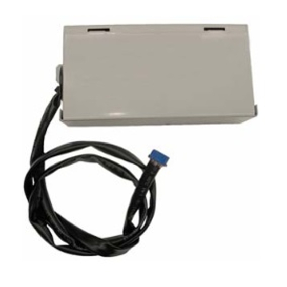
Auxiliary Heater Relay Kit (for Multi V Product)
PRARS1
MFL65920008
Rev.00_031620
Copyright © 2017 - 2020 LG Electronics Inc. All Rights Reserved.
www.lg.com
Advertisement
Table of Contents

Related Manuals for LG PRARS1


Summary of Contents for LG PRARS1
- Page 1 Please retain this installation manual for future reference after reading it thoroughly. Auxiliary Heater Relay Kit (for Multi V Product) PRARS1 www.lg.com MFL65920008 Rev.00_031620 Copyright © 2017 - 2020 LG Electronics Inc. All Rights Reserved.
- Page 2 IMPORTANT! Please read this instruction sheet completely before installing the product. This air conditioning system meets strict safety and operating standards. As the installer or service person, it is an important part of your job to install or service the system so it operates safely and efficiently. WARNING •...
-
Page 3: Table Of Contents
Table of Contents TABLE OF CONTENTS SAFETY PRECAUTIONS INCLUDED ITEMS ASSEMBLY DIAGRAM Assembly Diagram - PRARS1 Assembly Diagram - PRARS1 ELECTRICAL WIRING INSTALLER SETTING External devices of indoor unit setting (air conditioner) Outdoor temp. for heating stages (air conditioner) TROUBLESHOOTING GUIDE... -
Page 4: Safety Precautions
Safety Precautions 1. Safety Precautions To prevent injury to the user or other people and property damage, the following instructions must be followed. n Incorrect operation due to ignoring instruction will cause harm or damage. The seriousness is classified by the following indications. WARNING This symbol indicates the possibility of death or serious injury. - Page 5 2. Before installation, be sure to check all the included items. (How- ever, be sure to use all kinds of certified products when purchas- ing the items other than those provided by LG at your local store.) 3. Be sure to carry out the earth work. (However, do not connect the unit to gas pipe, water pipe, a lightning rod and a phone earth line.
-
Page 6: Included Items
Included Items 2. Included Items PRARS1 Model Screw Insulation Installation Manual Item Auxliary Heater Relay Kit Q’ty Figure • PRARS1 applies to Wall mounted and Art cool types. (Unit : inch) 7 9/32 6 23/32 1 13/32 6 Auxiliary Heater Relay Kit... -
Page 7: Assembly Diagram
Step2. Assemble PRARS1 with control box cover. Step3. Open the cover of PRARS1 and connect wires. Step4. Assemble control box cover. Note: While connecting the PRARS1, attach insulation at the rear of the Insulation control box cover where it receives screws as shown in Fig. A. - Page 8 Step2. Assemble PRARS1 with control box cover. Step3. Open the cover of PRARS1 and connect wires. Step4. Assemble control box cover. Note: While connecting the PRARS1, attach insulation at the rear of the Insulation control box cover where it receives screws as shown in Fig. A.
- Page 9 Step3. Open the cover of PRARS1 and connect wires. Step4. Assemble control box cover and front panel. Note: While connecting the PRARS1, attach insulation at the rear of the Insulation control box cover where it receives screws as shown in Fig. A.
- Page 10 Step3. Open the cover of PRARS1 and connect wires. Step4. Assemble control box cover and front panel. Note: While connecting the PRARS1, attach insulation at the rear of the Insulation control box cover where it receives screws as shown in Fig. A.
- Page 11 Step3. Open the cover of PRARS1 and connect wires. Step4. Assemble control box cover and front panel. Note: While connecting the PRARS1, attach insulation at the rear of the control box cover where it receives screws as shown in Fig. A.
- Page 12 Step1. Mount relay kit on the wall. Step2. Connect wires and assemble cover. CAUTION Do not install PRARS1 at, - Places which exposed to rain or any water. Other wise it may leads to electric shock, fire, injury or sometimes even fatality.
-
Page 13: Assembly Diagram - Prars1
Step1. Mount relay kit on the wall. Step2. Connect wires and assemble cover. CAUTION Do not install PRARS1 at, -Places which exposed to rain or any water. Other wise it may leads to electric shock, fire, injury or sometimes even fatality. -
Page 14: Electrical Wiring
Electrical Wiring 4. Electrical Wiring Party Scope RADIATOR RADIATOR Hot Water Hot Water External Power supply - Supply voltage : AC 24V LG Scope Indoor Unit CN_PTC DC12V Auxiliary Relay Kit CN_PTC1 14 Auxiliary Heater Relay Kit... - Page 15 Electrical Wiring Party Scope RADIATOR Hot Water External Power supply - Supply voltage : AC 24V LG Scope Indoor Unit CN_PTC DC12V Auxiliary Relay Kit CN_PTC1 Model : PREMBTB100 Installation Manual 15...
-
Page 16: Installer Setting
LG warrenty. • In the menu screen, press [<,>(left/right)] button to select the setting category, and press [∧(up)] button for 3 seconds to enter the password input screen for the installer setting. -
Page 17: External Devices Of Indoor Unit Setting (Air Conditioner)
Installer Setting External devices of indoor unit setting (air conditioner) At the Code field, select when air cleaner/heater/humidifier/elevation grill/ventilation KIT/Aux Heater/refrigerant leakage detection sensor are newly installed to the indoor unit or when an installed KIT is removed. • You can set the following setting values using [<,>(left/right)] button. Function Value Plasma purification... -
Page 18: Outdoor Temp. For Heating Stages (Air Conditioner)
Installer Setting Outdoor temp. for heating stages (air conditioner) It is a function that sets outdoor temperature values for two stage heating. if user set outdoor temperature T1 and T2, Indoor unit will select heating stage between Indoor unit operation and heater operation. T1 Value T2 Value -23 ~ 16 °C (-10 ~ 60 °F) -
Page 19: Troubleshooting Guide
Troubleshooting Guide 6. Troubleshooting Guide Symptom Check Action - Check the circuit breaker. Is air conditioner power turned - Check the AUX HEATER RELAY KIT installation status. Is the cable correctly connected - Connect the cable between the air condi- beteween the air conditioner tioner and AUX HEATER RELAY KIT. - Page 20 20 Auxiliary Heater Relay Kit...