
Related Manuals for ABB AC 900F


Summary of Contents for ABB AC 900F
- Page 1 Process Automation Freelance 2016 Mounting and Installation Instructions AC 900F Controller Power and productivity for a better world...
- Page 3 Freelance 2016 Mounting and Installation Instructions AC 900F Controller...
- Page 4 In no event shall ABB be liable for direct, indirect, special, incidental or consequential damages of any nature or kind arising from the use of this document, nor shall ABB be liable for incidental or consequential damages arising from use of any software or hard- ware described in this document.
-
Page 5: Table Of Contents
Table of Contents About this book Use of warning, caution, information, and tip icons .............. 9 Terminology.......................... 10 Section 1 - Overview AC 900F Controller ......................11 Features ........................13 Communication ........................14 System ........................14 Fieldbus ........................15 Section 2 - Configuration Configuration levels...................... - Page 6 PM 902F CPU module....................72 TU terminal blocks ....................73 CP-C switch-mode power supply units and CP-C RU redundancy unit....74 Wall mounting ........................76 PM 902F CPU module....................76 TU terminal blocks ....................77 Coupler bus slots ........................78 PM housing front........................79 Dimensional drawings......................80 M&I – AC 900F Controller...
- Page 7 Controller configuration via display unit................105 Boot configuration....................105 Section 8 - Service Module replacement ......................109 CI communication interfaces .................. 109 I/O modules ......................110 Replacement of accessories ....................110 TD 951F ........................110 M&I – AC 900F Controller...
- Page 8 TA 951F ........................137 TA 924F ........................138 TA 724F ........................139 Switch-mode power supply units and accessories ..............140 General technical data....................140 CP-C 24/5.0 ......................141 CP-C 24/10.0 ......................143 CP-C RU ........................145 CP-C MM ........................147 CP-A CM .........................149 Index M&I – AC 900F Controller...
-
Page 9: About This Book
Therefore, comply fully with all Warning and Caution notices. M&I – AC 900F Controller... -
Page 10: Terminology
Terminology About this book Terminology The Glossary contains terms and abbreviations that are unique to ABB or have a usage or definition that is different from standard industry usage. Please make yourself familiar to that. You will find the glossary at the end of the Engineering Manual System Configuration. -
Page 11: Section 1 Overview
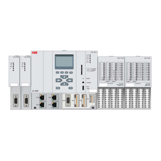
Section 1 Overview AC 900F Controller The PM 902F or PM 901F CPU module is the core component of an AC 900F controller. As there are only minor differences in appearance between both CPU module types, the drawings and photos of the PM 902F included in the present document also apply to the PM 901F. - Page 12 I/O modules, please refer to Mounting and Installation Instructions, I/O Modules for AC 700F / AC 900F. Similar to the AC 700F and AC 800F, the hardware configuration of the AC 900F is based on the hardware function block principle.
-
Page 13: Features
Section 1 Overview Features Features The AC 900F exhibits the following main features: CPU module – PowerPC (II Pro family) – RISC architecture Main memory – Main memory for data and application Battery – Lithium battery for RAM buffering Interfaces –... -
Page 14: Communication
The Control Net (Ethernet) connects the individual stations with each other. It transfers data between the controllers and between Freelance Operations, the gateways and Freelance Engineering. The AC 900F controller supports data sending and receiving through TCP/IP (Ethernet-based sending/receiving) and/or UDP/IP (lateral communication). -
Page 15: Fieldbus
This protocol variant is specifically designed for the communication between programmable controllers and a distributed I/O level. The AC 900F controller supports PROFIBUS Master redundancy. For additional information on PROFIBUS-DP and the PROFIBUS CI/CM modules,... - Page 16 Ethernet interface of the AC 900F. ABB CAN Bus protocol The CAN Bus of the AC 900F controller is intended to be used for connecting rack- based Freelance I/O modules only. With this feature, the current AC 900F controller CPU modules of type PM 902F/901F can alternatively take over the tasks of the CPU module types DCP 02/10 of the Freelance rack system.
-
Page 17: Section 2 Configuration
This section provides information on the AC 900F controller configuration for single and redundant operation. The AC 900F controller features a modular design. The basic components are a PM CPU module, CI/CM PROFIBUS communication interfaces and S700 I/O modules. The external 24 VDC voltage required to operate the controller can be provided by a CP-C power supply unit, for example. - Page 18 The high configuration level controller is composed of a PM CPU module and up to two CI modules for PROFIBUS communication. Alternatively, a CAN Bus module can be plugged into one of these two slots. S700 I/O modules are used as “direct I/O”. AC 900F_ Controller.png M&I – AC 900F Controller...
-
Page 19: Controller Redundancy
The S700 Direct I/O and the CM 772F communication module are not supported with redundant controller arrangement. M&I – AC 900F Controller... - Page 20 (component data, variables) is maintained. • the configuration and operating data of the primary and secondary controllers are automatically adapted. AC 900F in redundant configuration using the on-board interfaces for Modbus and telecontrol protocols. Controller Redundancy us.png M&I – AC 900F Controller...
- Page 21 Section 2 Configuration Controller redundancy Redundant AC 900F with PROFIBUS line redundancy in the field at a redundant Control Net. The figure below shows a configuration with PROFIBUS line redundancy using a CI 930F module. Line redundancy_us.png M&I – AC 900F Controller...
- Page 22 An existing PROFIBUS line in a single configuration with a CI 773F module can be enhanced to become a PROFIBUS with redundant lines by using additional RLM 01 modules, as shown in the following figure: Line Redundancy CI773F us.png M&I – AC 900F Controller...
-
Page 23: Section 3 Modules
Manual, Process Stations, and Engineering Manual, System Configuration, Hardware Structure. PM CPU modules The PM CPU module is the basic component of the AC 900F controller. It comes with a high-performance processor for multitasking and for processing tasks with short cycle times. -
Page 24: Cpu Modules Pm 902F And Pm 901F
2 slots for fieldbus communication interfaces • I/O bus for direct connection of I/O modules • On-board communication interfaces – Ethernet – RS 232/485 – I/O bus – Coupler bus • 24 V DC supply voltage • SD card reader M&I – AC 900F Controller... -
Page 25: Interfaces
SER1, depending on application – SER2, depending on application – DIAG, diagnostics, settings and radio clock Power supply unit – DC-IN +/-24 V DC Coupler bus – C1, C2 I/O bus – Connection on the right M&I – AC 900F Controller... - Page 26 Interfaces Section 3 Modules For more detailed information refer to the Mounting and Installation Instructions, I/O Modules for AC 700F / AC 900F. Power supply An external 24 V DC voltage supply of sufficient power is required for operating the CPU module, the modules on the C1/C2 slots and for the I/O bus.
- Page 27 For general information on safety and precautionary measures, please refer to the Safety Instructions for the AC 700F/AC 900F. Ethernet interfaces The on-board Ethernet network interfaces of 100 Mbit/s can be used for...
- Page 28 9.6 kBit/s (see Controller configuration via terminal program page 97). Coupler bus The PM CPU module features two C1/C2 coupler bus slots for the connection of additional communication interfaces, e.g. CI/CM PROFIBUS modules. M&I – AC 900F Controller...
- Page 29 The I/O bus on the right side of the PM CPU module is provided for communication with I/O modules that are directly connected to the CPU module. This bus serves for exchanging I/O data and diagnostic data between the CPU module and the I/O modules. IO_Bus_us.png M&I – AC 900F Controller...
-
Page 30: Led Display And Control Elements
Power supply not correctly connected Hardware error during self-test Flashing Error occurred, LED continues to flash until the sys- tem is stopped or started again No error Green AC 900F is operating RUN AC 900F was stopped STOP M&I – AC 900F Controller... - Page 31 – TOGGLE (Primary/ Secondary) – RESET RUN/STOP switch This switch is used to start and stop the program sequence. In redundant mode, the position of the RUN/STOP switch on the active AC 900F is used. M&I – AC 900F Controller...
- Page 32 Secondary will be ignored. RESET switch The RESET switch is used to reset the AC 900F. Depending on the system status, either a warm or a cold start is initiated. A “tool“ (e.g. a ball pen or similar) is required to actuate the RESET switch.
-
Page 33: Battery
Section 4, Accessories. CI/CM PROFIBUS modules The AC 900F is designed for operation with different PROFIBUS communication interfaces like the CI 930F, CI 773F and CM 772F that can be connected on the left side of the PM CPU module. -
Page 34: Ci 930F Profibus-Dp Master Interface
Testing and selection is always based on the first character. In the case of a telegram start with error on A, the control logic in CI 930F switches to the redundant line B. The same procedure applies vice-versa for line B. M&I – AC 900F Controller... - Page 35 D-SUB, 9-pin, female connector Internal power supply Via coupler bus LEDs Five LEDs for status display AC 900F Form factor Similar to AC 900F with PM 902F/901F Housing color Gray Number of slaves Controller redundancy support Yes Hot plug HCIR...
- Page 36 No data reception on lines A and B Green ON No data reception on line A, but data recep- tion on line B Green No data reception on line B, but data recep- tion on line A M&I – AC 900F Controller...
-
Page 37: Ci 773F Profibus-Dp Master Interface
PROFIBUS-DP master V0/V1 Fieldbus connection D-SUB, 9-pin, female connector Internal power supply Via coupler bus LEDs Four for status display AC 700F, AC 900F Form factor Similar to AC 700F with PM 783F Housing color Gray M&I – AC 900F Controller... - Page 38 Module has taken over the PROFIBUS master func- tion Module inactive relative to the PROFIBUS Green 200 ms Module ready to take over the master function pulse LED L Green Bus traffic No bus traffic M&I – AC 900F Controller...
-
Page 39: Cm 772F Profibus-Dp Master Interface
PROFIBUS-DP master V0/V1 Fieldbus connection D-SUB, 9-pin, female connector Internal power supply Via coupler bus LEDs Five LEDs for status display AC 700F, AC 900F Form factor Similar to AC 700F with PM 783F Housing color White M&I – AC 900F Controller... - Page 40 Hardware or system error Defective hardware Green Communication on Cyclic flashing Ready for communication Non-cyclic flashing Parameterization error No communication Yellow DP master: data or token are transmit- ted via the network DP master: No token M&I – AC 900F Controller...
-
Page 41: Profibus Connector And Cables
135…165 Cable capacity < 30 pF/m ≥ Cable core diameter 0.64 mm ≥ Cable core cross-section 0.34 mm Ω Resistance per cable core < 55 Ω Loop resistance (resistance of two cable < 110 cores) M&I – AC 900F Controller... - Page 42 PROFIBUS connector. As the bus termination is active, it must be ensured that both terminations are supplied with +5 V by a module or an external power supply. CM 772_Bus termination_us.png M&I – AC 900F Controller...
-
Page 43: Ci Can Bus Module
Section 3 Modules CI CAN Bus module CI CAN Bus module An AC 900F controller with CI 910F CAN Bus module allows for connecting rack- based I/O modules. CI 910F CAN Bus interface The CI 910F CAN Bus interface comprises three CAN Bus lines, CAN 1 to CAN 3. - Page 44 D-SUB, 9-pole, female Power supply Via coupler bus LEDs Five LEDs for status display Used with AC 900F Form factor Similar to AC 900F with PM 902F/901F Housing color Gray Controller redundancy support Hot plug M&I – AC 900F Controller...
- Page 45 Communication on CAN 2 channel No communication Yellow Flashing Sporadic transmission error Flashing Transmission interrupted (bus off mode) Green Flashing Communication on CAN 3 channel No communication Yellow Flashing Sporadic transmission error Flashing Transmission interrupted (bus off mode) M&I – AC 900F Controller...
-
Page 46: Connection Of Freelance I/O Racks
The CAN Bus connector of CI 910F features the following pin assignment: CAN_Bus_Pin assignment_us.png Connection of Freelance I/O racks When connecting the AC 900F controller to a Freelance rack, you have to remove the DCP 02/10 CPU modules. For detailed information about the accessories, e.g.regarding their function, pin assignment, wire color, cable length etc. - Page 47 Connection of Freelance I/O racks CAN single AC 900F at the beginning of the bus_us.png Redundant AC 900F controller at the beginning (end) of the CAN Bus The terminating resistors integrated into the TP 910F termination plug ensure that the termination and, thus, the function of the three CAN Bus lines is preserved even if a CAN bus module or controller is replaced.
- Page 48 Connection of Freelance I/O racks Section 3 Modules CAN redundant AC 900F at the beginning of the bus us.png M&I – AC 900F Controller...
-
Page 49: Cp-C Switch-Mode Power Supply Units And Accessories
Parallel operation In order to increase capacity or to ensure redundancy, devices of the same type can be connected in parallel. To ensure symmetric current distribution, the line connections should feature identical cross-section and length. M&I – AC 900F Controller... - Page 50 For this purpose, the power supply units connected in parallel are rated such as to ensure that the total power requirements of all loads can be entirely covered by a single power supply unit. CP_C24_parallel_operation_redundancy.png M&I – AC 900F Controller...
- Page 51 The secondary power supply unit side is galvanically isolated from the input and not internally earthed (SELV). It can be earthed by the user (either L+ or L-), if required (PELV). M&I – AC 900F Controller...
-
Page 52: Cp-A Ru Redundancy Unit
The output circuits are uncoupled by the CP-A RU redundancy unit as shown in the figure below. M&I – AC 900F Controller... - Page 53 Section 3 Modules CP-A RU redundancy unit CP-A RU_Parallel operation_real redundancy.png Electrical connection Input side [INPUT 1 + - / INPUT 2 + -] Connect the input terminals as shown in the figure below: CP-A RU_Circuit diagram.png M&I – AC 900F Controller...
-
Page 54: Cp-A Cm Control Module
A RU by means of LEDs and energized output relays. The output relay threshold values can be set between 14 und 28 V for each channel separately. If the voltage in one of the channels falls below the set threshold value M&I – AC 900F Controller... - Page 55 “IN 2 <V“. 21-22 closed and 21-24 opened when the voltage in channel 2 (IN 2) of the CP-A RU is lower than the threshold value set at “IN 2 <V“. M&I – AC 900F Controller...
-
Page 56: Cp-C Mm Messaging Module
If the “OUTPUT“ voltage of the power supply unit falls below 19.8 V DC, the “OUTPUT OK“ relay (contacts 21-22/24) is de-energized and the “OUTPUT OK“ LED goes off. The output voltage can only be monitored in uncoupled parallel operation. M&I – AC 900F Controller... - Page 57 21-24 closed and 21-22 opened, when the power supply unit output voltage is 20.2 V AC / V DC. 21-22 closed and 21-24 opened, when the power supply unit output voltage is 19.8 V AC / V DC. M&I – AC 900F Controller...
- Page 58 CP-C MM messaging module Section 3 Modules M&I – AC 900F Controller...
-
Page 59: Section 4 Accessories
TD 951F display unit The TD 951F display unit is an optional AC 900F accessory. It features a dot-matrix LCD display with 128 x 64 pixel resolution as well as keys with fixed and variable functions. - Page 60 Function keys F1 to F4. Select a menu or enable a function. For de- tails about menus and functions refer to Section 7 and 8. Move right or select next Move left or select previous M&I – AC 900F Controller...
-
Page 61: Ta 951F Battery For Ram Buffering
TA 951F battery for RAM buffering Battery_TA 951F.png The accessory TA 951F comprises a 2/3A lithium battery with connecting cable. The battery is provided with a plastic sheathing. This battery can be replaced while the AC 900F is in operation. • Cylindrical lithium cell •... - Page 62 Risk of overheating and subsequent explosion! Batteries must not be short-circuited, recharged, opened or thrown into fire! Store the batteries in a dry place. Strictly observe the applicable local recycling and environmental regulations during disposal of used batteries. M&I – AC 900F Controller...
-
Page 63: Dummy Couplers Ta 924F And Ta 724F
The dummy couplers are designed to protect unused slots against contact (ESD), corrosion and other effects. TA_724F.png Features TA 924F Form factor Similar to AC 900F with PM 902F/901F Height 152 mm TA 724F Form factor Similar to AC 700F with PM 783F... -
Page 64: Diagnostic Cables Tk 890F And Tk 891F
• TK 891F with 5 m length The TK 890F or TK 891F cable connects the AC 900F to the 9-pin port of the PC provided for diagnostic purposes. For interfaces with a 25-pin connector, a commercial adapter is additionally required. The energized diagnostic PC can be connected to the running AC 900F. - Page 65 Section 4 Accessories TA525 inscription labels The labels are provided to mark the various AC 900F modules (CPU module, communication interfaces and I/O modules). Waterproof felt pins can be used for labelling. Handling instructions Insert the label with slight pressure. To remove the label, a small screwdriver is inserted at the lower edge of the label.
-
Page 66: Can Bus Accessories
The TP 910F termination plug serves for terminating (with correct impedance level) three CAN bus lines directly at the CI 910F CAN Bus interface module. The screw terminals in the plug allow to connect either the TK 811F open-end CAN cable or a commercial twisted-pair cable. M&I – AC 900F Controller... -
Page 67: Tk 811F Can Cable
The TK 811F cable connects the Freelance I/O racks to the CI 910F module. The six wires and the cable shield are connected to the TP 910F terminal plug or a preceding TB 870F terminal block. M&I – AC 900F Controller... -
Page 68: Tk 831F Can Cable
Connector pin assignment Channel Signal Pins D-SUB 25 Pins D-SUB 9 CAN 1H 1, 14 CAN 1L 2, 15 CAN 2H 4, 17 CAN 2L 5, 18 CAN 3H 7, 20 CAN 3L 8, 21 M&I – AC 900F Controller... -
Page 69: Tb 870F Terminal Block
It is also used to connect a controller in the middle of a CAN bus line between two I/O racks. Terminal strips Channel Signal Input terminals Output terminals CAN 1H CAN 1L CAN 2H CAN 2L CAN 3H CAN 3L M&I – AC 900F Controller... - Page 70 TB 870F terminal block Section 4 Accessories M&I – AC 900F Controller...
-
Page 71: Section 5 Mounting
Section 5 Mounting This section provides information on initial mounting and removal of the modules and accessories of an AC 900F controller. These operations must be performed while all components are de-energized. Prior to performing any mounting or demounting operations, switch off the controller and associated devices and secure the equipment against unintentional start-up. -
Page 72: Mounting To The Din Rail
Snap the PM CPU module onto the DIN rail. For this purpose, the module must be placed on top of the rail and pushed downwards until it locks in place. Mounting_1.png To remove the module from the DIN rail, press it down and pull it off the rail. SYSDAT32.png M&I – AC 900F Controller... -
Page 73: Tu Terminal Blocks
To remove the terminal blocks, carefully insert a screwdriver between both elements and slide them apart, as shown in the figure. For this purpose, the elements are provided with a recess designed for the insertion of a screwdriver tip. SYSDAT35.png M&I – AC 900F Controller... -
Page 74: Cp-C Switch-Mode Power Supply Units And Cp-C Ru Redundancy Unit
Slightly shake the module to check whether it is correctly locked. PS_Mount_us.png To remove the CP-C or CP-C RU, proceed as follows: Unlock the module using a screwdriver. Tilt the module and remove it to the top. PS_Dismount.png M&I – AC 900F Controller... - Page 75 To remove the CP-C MM and CP-A CM modules, carefully press and tilt them upwards. Pull the module downwards to unlock the locking latch and remove the CP-C MM or the CP-A CM module from the power supply unit or the redundancy unit, respectively. CP-C MM_CM_Dismount.png M&I – AC 900F Controller...
-
Page 76: Wall Mounting
Wall mounting Section 5 Mounting Wall mounting Wall mounting is an alternative to DIN rail mounting of the AC 900F controller. The description below generally also applies for installation on a mounting panel inside a cabinet. PM 902F CPU module The 902F PM CPU module features four bores for screws on the rear side of the housing (see arrows). -
Page 77: Tu Terminal Blocks
Use two M4 screws per terminal block for this purpose. The screws must be inserted at the terminal block front. TA526 wall mounting.png M&I – AC 900F Controller... -
Page 78: Coupler Bus Slots
Coupler bus slots The C1 and C2 coupler bus slots serve for connecting the CI/CM communication interfaces to the CPU module. When configuring the AC 900F controller and integrating a CI/CM module, the bottom module part must be plugged in first. Then press the module backwards until it locks in place at the top of the slot. -
Page 79: Pm Housing Front
The central area of the housing front of the CPU module is equipped with a removable cover. This cover can be taken off without any tools and be replaced by a TD display unit. display.png M&I – AC 900F Controller... -
Page 80: Dimensional Drawings
Dimensional drawings Section 5 Mounting Dimensional drawings Note: All dimensions are indicated in mm. Dimensional drawings of the PM CPU-module Front view AC 900F_dimensions.png Lateral view AC 900F_depth.png M&I – AC 900F Controller... -
Page 81: Dimensional Drawings Of The Cp-C 24/5.0 And Cp-C 24/10.0
Install the devices in upright position with the input terminals being arranged at the bottom. In order to ensure sufficient convection cooling, the minimum distance to other modules must not be less than 80 mm in vertical and 10 mm in horizontal direction. M&I – AC 900F Controller... -
Page 82: Dimensional Drawing Of The Cp-A Ru
(A) 10 mm in horizontal direction and (B) 50 mm in vertical direction. Dimensional drawings of the CP-C MM and CP-A CM CP-C MM_CP-A CM.png The CP-C MM and CP-A CM modules have identical dimensions. M&I – AC 900F Controller... -
Page 83: Section 6 Wiring
Section 6 Wiring This section provides information on wiring the AC 900F controller exclusive of the CI/CM communication interface module. It contains safety instructions, general guidelines and information on cable routing. Safety instructions Make sure to strictly observe the following safety instructions when wiring the controller. -
Page 84: Controller Earthing
CPU module. l The controller is earthed through the DIN rail or both lower fastening screws. Use yellow chromated steel DIN rails to ensure proper earthing. M&I – AC 900F Controller... -
Page 85: Cable Routing
Earth the cable shield using a clamp directly at the entry into the switch cabinet. Guide the shield up to the module without any interruption. • There must be a low-impedance connection between the PE bar and the shield bar. M&I – AC 900F Controller... -
Page 86: Switch Cabinet
Reference potential • Ensure a uniform reference potential throughout the line and earth the complete electrical equipment, as far as possible. • Install the earth conductors in star configuration to avoid the formation of ground loops. M&I – AC 900F Controller... -
Page 87: Equipotential Bonding
Fuse for the CPU module Power supply unit for the I/O modules *) Fuse for the I/O modules * Fuses for the relay output contacts see module description 0V rail (signal reference potential) Earthing of the 0V rail M&I – AC 900F Controller... -
Page 88: Power Consumption
ZP and UP terminals of the terminal blocks. The power for the consumers at the digital/analog outputs and the electronics inside the I/O module is also supplied from here. M&I – AC 900F Controller... -
Page 89: Fuse Dimensions
(melting integral of the upstream fuse) must be taken into account. Module type PM 902F and PM 901F Total melting integrals 22 A Rated current 4.0 A Characteristic AT high breaking capacity Recommended fuse protection Type IEC/EN60127-2/V Dimensions Glass tube fuse, 5x20 mm M&I – AC 900F Controller... -
Page 90: Bus Termination
RxD/TxD-N per bus. These two resistors are designed to ensure a defined high level on the bus when no data are transmitted. • shielded twisted-pair cables with an impedance level of 100 to 120 Ohm. M&I – AC 900F Controller... - Page 91 The external 120 ohm resistor (line termination) must be protected against electrostatic discharge. It is recommended to provide the complete resistor (except for the wire ends) with a heat shrink tube for this purpose. Ethernet_Connect_us.png M&I – AC 900F Controller...
- Page 92 The terminal strips must be arranged as close as possible to the controller. In this configuration, the pull up/down resistors of the CPU module are not required. RS232 RS 232 redundant PM.png M&I – AC 900F Controller...
- Page 93 RS484 bus. . The 5 V DC power supply unit must have a safe electrical isolation. As described earlier in this section, the external resistors must be protected against electrostatic discharge. M&I – AC 900F Controller...
- Page 94 However, this must only be taken into consideration if the components are operated in half duplex mode, as the CSMA/CD access process is only used in this case. If all components work in full duplex mode, no collisions will be caused. M&I – AC 900F Controller...
-
Page 95: Section 7 Commissioning
Module with battery compartment (new) Push the battery to the left into the battery compartment. It will be locked in place by the front panel or the display unit. M&I – AC 900F Controller... - Page 96 To connect the battery to the power supply, plug in the battery connector into the mating socket. The connector is keyed to ensure reverse polarity protection. Close the housing with the previously removed front panel or display unit. Battery_04_us.png M&I – AC 900F Controller...
-
Page 97: Controller Configuration Via Terminal Program
Data bits: Stop bits: Hardware self-test A hardware self-test is performed with every start of the AC 900F. The controller system messages are indicated via the diagnostic interface (DIAG). Boot loader configuration When the AC 900F is started, the boot loader displays a configuration message showing the Firmware version number in the header. - Page 98 Controller configuration via terminal program Section 7 Commissioning M&I – AC 900F Controller...
- Page 99 An IP address must be assigned to each Ethernet interface in the various subnets. It is recommended to set an IP address within the range of 172.16.[0 - 15].[0 - 255] for the Control Net. M&I – AC 900F Controller...
- Page 100 ETH1. Set Ethernet link 1 configuration: 0. Auto negotiation 1. 100 MBit full duplex 2. 100 MBit half duplex 3. 10 MBit full duplex 4. 10 MBit half duplex Select: [0] M&I – AC 900F Controller...
- Page 101 Select [6] to configure the controller for the connection to a redundant Control Net. ETH3 will then operate with the setting 10/100 MBit auto. ETH4 Set Ethernet link 4 configuration: 0. 10/100 MBit auto 7. Offline Select: [7] M&I – AC 900F Controller...
- Page 102 It is recommended not to change the default setting. The boot loader then displays the current configuration data that are still to be saved. The default setting for all other parameters must not be changed! M&I – AC 900F Controller...
- Page 103 Date and time Select the <T>ime menu item, which will allow you to set the time and date of the battery buffered real-time clock of the AC 900F. The order of the date format is day, month, year. Enter date <dd.mm.yy>: 22.07.12 The order of the time format is hour, minute, second.
- Page 104 RTC time: 22.07.08, 00:17:02 local Date and time must be precisely set during first commissioning of the AC 900F. Identification PIN Select the <P>in menu item in order to define an identification PIN.
-
Page 105: Controller Configuration Via Display Unit
F1:IP addresses Control Net Gateway Redundancy F1: ETH1 F2: ETH2 F3: ETH3 F4: ETH4 F2: Update/Restore Please refer to section 8 “Service” F3: Display settings Backlight Contrast The Boot Configuration menu features three submenus. Boot_Config.png M&I – AC 900F Controller... - Page 106 F1 - IP Address IP Address setting is mandatory to communicate with the AC 900F via Ethernet. Press F1 to access the Network submenu. The IP address of the Gwy:000.000.000.000...
- Page 107 Ethernet_enabled-02.png Eth3 can be freely used. If the controller will be connected to a Redundant Network (redundant Control Net), Eth3 (line B) is required in addition to Eth1 (line A). M&I – AC 900F Controller...
- Page 108 For more detailed information on these functions, please refer to Update/Restore in Section 8, Service. F3 - Display Settings Adjust the Backlight and the Contrast using the arrow keys provided for both menu items. Display_Settings.png Press the OK key to apply the settings. M&I – AC 900F Controller...
-
Page 109: Section 8 Service
There are several possibilities to connect or disconnect a communication interface to/from a C1/C2 slot without disturbing the CPU module. AC 900F in de-energized state After having de-energized the controller, press on the lock at the top of the CI/CM communication interface and disconnect the module from the slot. -
Page 110: I/O Modules
Insertion of the TA 951F battery on page 95. Lithium batteries must not be recharged, opened or thrown into fire. Store the batteries in a dry place. Strictly observe the applicable local environmental regulations during disposal of used batteries. M&I – AC 900F Controller... -
Page 111: Online Functions Of The Display Unit
C2 slot F2: Backup configuration on SD card F3: Save memory image on SD card Boot configuration (offline) F2: Update/Restore F1: Restore configuration from SD card F2: Firmware update from SD card F3: Enable autorestore M&I – AC 900F Controller... -
Page 112: Start Menu
Section 8 Service Start menu The start menu of the AC 900F display is generally the starting point for performing the functions described in this section. Press the ESC key to quit the start menu or to return to the start menu. -
Page 113: Main Menu
When the ESC key is pressed, the Main menu is displayed. This menu provides access to the Controller menu via F1 and to the Maintenance menu via F2. Main menu.png Controller menu The Controller menu provides access to the Security and Restart submenus. Controller_restart.png M&I – AC 900F Controller... - Page 114 Access to the controller Webserver and Telnet can be blocked by the configuration. This setting can only be entered in Freelance Engineering and not on the display unit. AC 900F Parameters > CPU/Security > Security > Webserver disabled or Telnet disabled F1 function: Change PIN By entering a PIN, access to the Controller menu and the use of the functions included in this menu by unauthorized persons is excluded.
- Page 115 The Run/Stop switch can only be disabled in Freelance Engineering and not on the display unit. AC 900F Parameters > CPU/Security > Security > Run/Stop switch F3 - Restart The functions provided in the Restart submenu allow the controller to be started in different ways.
-
Page 116: Maintenance Menu
The entire user configuration is cancelled. Output modules indicate the set security values. Restart the controller to load a new configuration. Maintenance menu Select the Maintenance menu to access the Module exchange, Backup config and Save memory image functions. Maintenance screen.png M&I – AC 900F Controller... - Page 117 SD card. The file with the backup copy has the name <IP Address>.CFI, with the IP address being indicated in hexadecimal format. During the saving process, the controller remains in operation, but downloads are rejected. M&I – AC 900F Controller...
- Page 118 As soon as the process is completed, an OK message appears on the display. The file with the memory contents has the name <IP Address>.MEM, with the IP address being indicated in hexadecimal format. During the saving process, the controller remains in operation, but downloads are rejected. M&I – AC 900F Controller...
-
Page 119: Offline Functions Of The Display Unit
The menu (Update/Restore) provides three F1 - F3 functions. Restore.png F1 - Restore config The controller searches the configuration (application/project) on the SD card under the file name that corresponds to the IP address in hexadecimal format. M&I – AC 900F Controller... - Page 120 CPU module. Upon restoring or updating, the controller is automatically rebooted. Depending on the file size, this process can take several seconds (loading..is displayed). As soon as the ABB logo appears, you can remove the SD card from the slot.
- Page 121 Update/Restore CPU module without battery This AC 900F operating mode is recommended with regular supply voltage failures for a longer period of time, e.g. with solar energy supply. As no energy is supplied at night (buffering mode), the battery would be discharged within less than two years.
- Page 122 Update/Restore Section 8 Service M&I – AC 900F Controller...
-
Page 123: Section 9 Technical Data
Do not disconnect while circuit is live unless area is known to be non-hazardous. Substitution of any components may impair suitability for class 1, division 2. Batteries must only be changed in an area known to be non-hazardous. M&I – AC 900F Controller... -
Page 124: Modules And Accessories
0 to 60 °C. An adaptation of the approval to an extended temperature range of -20 to +70 °C has been applied for at UL. The application does not include the CM 772F and TA 724F modules. M&I – AC 900F Controller... -
Page 125: Pm 902F, Pm 901F
8 MB, PM 902F buffered 3 MB, PM 901F Application and data 16 MB RAM buffering Buffer time at Ta +40 °C > 2 years Residual buffer time 14 days, after warning Real-time clock with buffer battery M&I – AC 900F Controller... - Page 126 CI 930F, CI 773F, CM 772F SD card reader/writer Supported SD cards Standard size SD, 32 x 24 mm with adapter miniSD, microSD Capacity max. 32 GB Specification SD, SDHC Supported file system FAT, FAT32 M&I – AC 900F Controller...
- Page 127 - 40 ... +85 °C Storage (installed TD 951F) - 25 ... +85 °C Certificates Declaration of conformity ANSI/ISA 71.04-1985 G3 Approvals PM 902F cULus UL Class 1 Div 2 (groups A, B, C, D) PM 901F In preparation M&I – AC 900F Controller...
- Page 128 Dimensions W x H x D CI 930F 3BDH...R0005 28 x 152 x 75 mm CI 930F 3BDH...R0001 28 x 135 x 75 mm Weight 117 g Type of protection IP 20 Status indicators LEDs PWR, STA, RUN, A, B M&I – AC 900F Controller...
- Page 129 CI 930F Ambient temperature Operation - 20 ... +70 °C Storage - 40 ... +85 °C Certificates Declaration of conformity ANSI/ISA 71.04-1985 G3 Approvals cULus UL Class 1 Div 2 (Groups A, B, C, D) M&I – AC 900F Controller...
- Page 130 102 g Type of protection IP 20 Status indicators LEDs PWR, STA, RUN, L Ambient temperature Operation - 20 ... +70 °C Storage - 40 ... +70 °C Certificates Declaration of conformity ANSI/ISA 71.04-1985 G3 M&I – AC 900F Controller...
- Page 131 Section 9 Technical Data CI 773F Approvals cULus UL Class 1 Div 2 (Groups A, B, C, D) M&I – AC 900F Controller...
- Page 132 28 x 135 x 75 mm Weight 96 g Type of protection IP 20 Status indicators LEDs PWR, RDY, RUN, STA, ERR Ambient temperature Operation 0 ... +60 °C Storage - 25 ... +75 °C M&I – AC 900F Controller...
- Page 133 Section 9 Technical Data CM 772F Certificates Declaration of conformity Approvals cULus UL Class 1 Div 2 (Groups A, B, C, D) EAC, GL M&I – AC 900F Controller...
- Page 134 28 x 152 x 75 mm Weight 178 g Type of protection IP 20 Status indicators LEDs PWR, STA, L1, L2 , L3 Ambient temperature Operation - 20 ... +70 °C Storage - 40 ... +85 °C M&I – AC 900F Controller...
-
Page 135: Certificates
Section 9 Technical Data Certificates Certificates Declaration of conformity Approvals (pending) ANSI/ISA 71.04-1985 G3 cULus UL Class 1 Div 2 (Groups A, B, C, D), M&I – AC 900F Controller... - Page 136 0.35 W Ambient temperature Operation - 20 ... +70 °C Storage - 25 ... +70 °C Certificates Declaration of conformity ANSI/ISA 71.04-1985 G3 Approvals cULus UL Class 1 Div 2 (Groups A, B, C, D) M&I – AC 900F Controller...
- Page 137 Battery type Non-rechargeable Ambient temperature Operation - 40 ... +70 °C Storage - 40 ... +70 °C Certificates Declaration of conformity ANSI/ISA 71.04-1985 G3 Approvals cULus UL Class 1 Div 2 (Groups A, B, C, D) M&I – AC 900F Controller...
- Page 138 Type of protection IP 20 Ambient temperature Operation - 20 ... +70 °C Storage - 40 ... +85 °C Certificates Declaration of conformity Approvals cULus UL Class 1 Div 2 (Groups A, B, C, D) M&I – AC 900F Controller...
- Page 139 50 g Type of protection IP 20 Ambient temperature Operation 0 ... +60 °C Storage - 25 ... +75 °C Certificates Declaration of conformity Approvals cULus UL Class 1 Div 2 (groups A, B, C, D) M&I – AC 900F Controller...
-
Page 140: Switch-Mode Power Supply Units And Accessories
IEC/EN 61204 Low voltage directive 2006/95/EC EMC directive 2004/108/EC Electrical safety EN 50178, EN 60950, UL 60950, UL 508 Safety extra low voltage SELV (EN 60950) Interference immunity IEC/EN 61000-6-2 Emitted interference IEC/EN 61000-6-3, class B M&I – AC 900F Controller... -
Page 141: Cp-C 24/5.0
Rated power 120 W Power dissipation < 15 W Short-circuit current limiting 11 A Starting of capacitive loads Unlimited Resistance to Short-circuit, no load and overload Status indicators OUTPUT OK, green LED Output voltage OK M&I – AC 900F Controller... - Page 142 UL Class 1 Div 2 (Groups A, B, C, D) The voltage as well as the input and output wiring must comply with the requirements specified for Class I, Div. 2 - Article 501-10(B) (1) NEC. M&I – AC 900F Controller...
-
Page 143: Cp-C 24/10.0
Rated power 240 W Power dissipation < 29 W Short-circuit current limiting 19 A Starting of capacitive loads Unlimited Resistance to Short-circuit, no load and overload Status indicators OUTPUT OK, green LED Output voltage OK M&I – AC 900F Controller... - Page 144 UL Class 1 Div 2 (Groups A, B, C, D) The voltage as well as the input and output wiring must comply with the requirements specified for Class I, Div. 2 - Article 501-10(B) (1) NEC. M&I – AC 900F Controller...
-
Page 145: Cp-C Ru
> 10 mm horizontal, > 50 mm vertical Type of protection IP 20 Electrical connection Wire size Finely stranded with wire end 2.5 - 10 mm errule Finely stranded without wire 0.5 - 10 mm end ferrule M&I – AC 900F Controller... - Page 146 (Protection class I). Ambient temperature Operation with derating - 25 ... +70 °C Operation at rated current - 25 ... +60 °C Storage - 40 ... +85 °C Certificates Declaration of conformity Approvals cULus, M&I – AC 900F Controller...
-
Page 147: Cp-C Mm
Rated current at 24 V / 230 V 1 A, ohmic and inductive load Switching cycle 0.1 x 10 Monitoring function Monitoring Low voltage detection Input threshold value(s) 85 V AC / 90 V DC Output threshold value(s) 20 V DC M&I – AC 900F Controller... - Page 148 Finely stranded without wire end 0.2 - 2.5 mm ferrule Rigid 0.2 - 4 mm Protection class Ambient temperature Operation - 25 ... +70 °C Storage - 40 ... +85 °C Certificates Declaration of conformity Approvals cULus M&I – AC 900F Controller...
-
Page 149: Cp-A Cm
Value of channel 2 = no error Output voltage > 3 V = OK Mechanical data Dimensions (W x H x D ) 56.5 x 54 x 24 mm Weight 63 g Type of protection IP 20 M&I – AC 900F Controller... - Page 150 Finely stranded without wire end 0.2 - 2.5 mm ferrule Rigid 0.2 - 4 mm Protection class Ambient temperature Operation - 25 ... +70 °C Storage - 40 ... +85 °C Certificates Declaration of conformity Approvals cULus M&I – AC 900F Controller...
- Page 151 Do not disconnect while circuit is live unless area is known to be non-hazardous. Substitution of any components may impair suitability for class 1, division 2. Batteries must only be changed in an area known to be non-hazardous. M&I – AC 900F Controller...
- Page 152 CP-A CM Section 9 Technical Data M&I – AC 900F Controller...
-
Page 153: Index
Diagnostic interface transmission rate ..102 Display and control elements ......30 Dummy coupler ..........17 Ethernet ............94 I/O bus ............13, 25 Interfaces ............13 Main memory ..........13 Messaging module Electrical connection ....... 57 M&I – AC 900F Controller... - Page 154 Index M&I – AC 900F Controller...
- Page 156 With regard to purchase orders, the agreed particulars shall pre- vail. ABB does not assume any responsibility for any errors or incomplete information in this document. We reserve all rights to this document and the items and images it contains.