Table of Contents
Advertisement
Quick Links
Advertisement
Table of Contents

Related Manuals for Asus AAEON FWS-8600


Summary of Contents for Asus AAEON FWS-8600
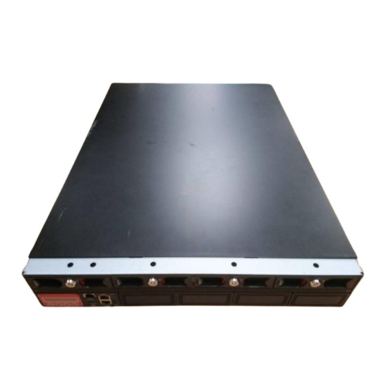
- Page 1 FWS-8600 Network Appliance User’s Manual 1 Last Updated: September 23, 2019...
- Page 2 Copyright Notice This document is copyrighted, 2019. All rights are reserved. The original manufacturer reserves the right to make improvements to the products described in this manual at any time without notice. No part of this manual may be reproduced, copied, translated, or transmitted in any form or by any means without the prior written permission of the original manufacturer.
- Page 3 Acknowledgement All other products’ name or trademarks are properties of their respective owners. Microsoft Windows is a registered trademark of Microsoft Corp. Intel, Xeon, and Xeon SP are registered trademarks of Intel Corporation ITE is a trademark of Integrated Technology Express, Inc. ...
- Page 4 Packing List Before setting up your product, please make sure the following items have been shipped: Item Quantity FWS-8600 Gift Box (Including Console Cable x 1, SATA Cable x 1, SATA Power Cable x 1, and Ear Bracket Kit x 1) CPU cooler ...
- Page 5 About this Document This User’s Manual contains all the essential information, such as detailed descriptions and explanations on the product’s hardware and software features (if any), its specifications, dimensions, jumper/connector settings/definitions, and driver installation instructions (if any), to facilitate users in setting up their product. Users may refer to the product page at AAEON.com for the latest version of this document.
- Page 6 Safety Precautions Please read the following safety instructions carefully. It is advised that you keep this manual for future references All cautions and warnings on the device should be noted. All cables and adapters supplied by AAEON are certified and in accordance with the material safety laws and regulations of the country of sale.
- Page 7 As most electronic components are sensitive to static electrical charge, be sure to ground yourself to prevent static charge when installing the internal components. Use a grounding wrist strap and contain all electronic components in any static-shielded containers. If any of the following situations arises, please the contact our service personnel: Damaged power cord or plug Liquid intrusion to the device iii.
- Page 8 FCC Statement This device complies with Part 15 FCC Rules. Operation is subject to the following two conditions: (1) this device may not cause harmful interference, and (2) this device must accept any interference received including interference that may cause undesired operation.
- Page 9 China RoHS Requirements (CN) 产品中有毒有害物质或元素名称及含量 AAEON System QO4-381 Rev.A0 有毒有害物质或元素 部件名称 铅 汞 镉 六价铬 多溴联苯 多溴二苯醚 (Pb) (Hg) (Cd) (Cr(VI)) (PBB) (PBDE) 印刷电路板 × ○ ○ ○ ○ ○ 及其电子组件 外部信号 × ○ ○ ○ ○ ○ 连接器及线材 ○ ○...
- Page 10 China RoHS Requirement (EN) Hazardous and Toxic Materials List AAEON System QO4-381 Rev.A0 Hazardous or Toxic Materials or Elements Component Name PCB and Components Wires & Connectors for Ext. Connections Chassis CPU & RAM HDD Drive LCD Module Optical Drive Touch Control Module Battery This form is prepared in compliance with the provisions of SJ/T 11364.
-
Page 11: Table Of Contents
Table of Contents Chapter 1 - Product Specifications ....................1 Specifications ....................... 2 Chapter 2 – Hardware Information ..................... 5 Dimensions ........................6 2.1.1 System ......................6 2.1.2 Board ......................7 2.1.3 PER-T488 Expansion Riser ............... 9 2.1.4 PER-T489 I/O Card................... 10 Jumpers and Connectors .................. - Page 12 Installing Network Interface Module (NIM) ............30 Chapter 3 - AMI BIOS Setup ...................... 32 System Test and Initialization................. 33 AMI BIOS Setup ......................34 Setup Submenu: Main .................... 35 Setup Submenu: Advanced ................... 36 3.4.1 Advanced: Trusted Computing ............37 3.4.2 Advanced: USB Configuration ..............
- Page 13 3.8.1 Platform Configuration: PCH Configuration ........71 3.8.1.1 PCH SATA Configuration ............72 3.8.1.2 PCH sSATA Configuration ............73 3.8.2 Platform Configuration: Server ME Configuration ......74 Setup Submenu: Socket Configuration .............. 75 3.9.1 Socket Configuration: Processor Configuration ......76 3.9.2 Socket Configuration: Memory Configuration ........
-
Page 14: Chapter 1 - Product Specifications
Chapter 1 Chapter 1 - Product Specifications... -
Page 15: Specifications
Specifications Platform Form Factor 2U Rackmount Network Platform Processor Dual Intel® Xeon® Processor Skylake-SP & Cascade Lake-SP processor Chipset Intel®C621 System Memory DDR4 2133/2400/2666 R-DIMM, Up to 512 GB Network Ethernet Intel® i211 Gigabit Ethernet x 2 Bypass Depends on NIM module NIM Slot NIM x 4 (up to NIM x 8) Display... - Page 16 Internal/Expansion Interface IPMI — Keyboard and Mouse — USB 3.0 x 2 (USB 3.0 x 2 ,Box Header 2.0mm optional) Miscellaneous Internal RTC Watchdog Timer 1~255 steps by software programmable Software Button GPIO Programmable push button x 1 TPM 2.0 9665 (TPM v1.2 9660 optional) GPIO 4 bits input, 4 bits output (optional) MTBF (Hours)
- Page 17 Environmental Parameters and Dimension Dimension (W X D X H) 17.48” x 22.83” x3.46” (444mm x 580mm x 88mm) I/O Interfaces Front Panel Power LED x 1 Status LED x 1 HDD Active LED x 1 USB 3.0 Ports x 2 RJ-45 Console x 1 Parallel LCM display and 4 keypad x 1 Software Programmable Button x1...
-
Page 18: Chapter 2 - Hardware Information
Chapter 2 Chapter 2 – Hardware Information... -
Page 19: Dimensions
Dimensions 2.1.1 System Chapter 2 – Hardware Information... -
Page 20: Board
2.1.2 Board Top and Front Chapter 2 – Hardware Information... - Page 21 Bottom and Side Chapter 2 – Hardware Information...
-
Page 22: Per-T488 Expansion Riser
2.1.3 PER-T488 Expansion Riser Chapter 2 – Hardware Information... -
Page 23: Per-T489 I/O Card
2.1.4 PER-T489 I/O Card Chapter 2 – Hardware Information... -
Page 24: Jumpers And Connectors
Jumpers and Connectors 2.2.1 Board Top and Front Chapter 2 – Hardware Information... - Page 25 Bottom and Side Chapter 2 – Hardware Information...
-
Page 26: Per-T488 Expansion Riser
2.2.2 PER-T488 Expansion Riser Chapter 2 – Hardware Information... -
Page 27: Per-T489 I/O Card
2.2.3 PER-T489 I/O Card Chapter 2 – Hardware Information... -
Page 28: List Of Jumpers
List of Jumpers Please refer to the table below for all of the board’s jumpers that you can configure for your application Label Function CMOS1 RTC Reset Auto Power Button 2.3.1 RTC Reset (CMOS1) Normal (Default) Clear CMOS 2.3.2 Auto Power Button (PWRBTN) Selection (JP2) 1 2 3 Disabled (Default) Enabled... -
Page 29: List Of Connectors
List of Connectors Please refer to the table below for all of the board’s connectors that you can configure for your application Label Function ATX1 24-pin ATX Power Connector ATX_CPU1~2 8-pin 12V Power Connector 20-pin smart fan Mini PCIe socket LCM Connector CN11~16 HDD Power Connector... -
Page 30: Digital I/O (Dio1)
2.4.1 Digital I/O (DIO1) Signal Signal Type DIO0 Input/ Output DIO1 Input/ Output DIO2 Input/ Output DIO3 Input/ Output DIO4 Input/ Output DIO5 Input/ Output DIO6 Input/ Output DIO7 Input/ Output +3.3V Chapter 2 – Hardware Information... -
Page 31: Lcm Connector (Cn6)
2.4.2 LCM Connector (CN6) Signal Signal Type LCMGND LCMVCC SLIN- Output INIT Output AFD- Output PTD0 Input/ Output PTD1 Input/ Output PTD2 Input/ Output PTD3 Input/ Output PTD4 Input/ Output PTD5 Input/ Output PTD6 Input/ Output PTD7 Input/ Output LCD- Output Chapter 2 –... -
Page 32: Keypad Connector (Cn24)
2.4.3 Keypad Connector (CN24) Signal Signal Type KEY PAD Down Input KEY PAD Up Input KEY PAD Right Input KEY PAD Left Input 2.4.4 HDD Power Connector (CN11~CN16) Signal Signal Type +12V 2.4.5 USB 3.0 Port (USB1) Signal Signal Type Signal Signal Type +5V_USB... -
Page 33: Front Panel Connector 2 (Fp2)
2.4.7 Front Panel Connector 2 (FP2) Signal Signal Type Power On Button(+) Input Power On Button(-) Reset Switch (+) Input Reset Switch (-) HDD LED (+) Output HDD LED (-) Output Power LED(+) POWER Power LED(-) 2.4.8 Front Panel Connector 1 (FP1) Signal Signal Type PMBUS_SML1_SCL... -
Page 34: Installing Chassis Mounted Hard Drive
Installing Chassis Mounted Hard Drive This section details how to install the system chassis mounted hard drive assembly using either two 2.5” HDDs or one 3.5” HDD. Remove the highlighted screws. Slide lid towards back, then lift to remove. Chapter 2 – Hardware Information... - Page 35 Remove the five highlighted screws securing the HDD tray. Note, you must remove the leftmost HDD bay to access the screw located there. Shift the HDD tray back, then lift to remove from the system. Chapter 2 – Hardware Information...
- Page 36 (Step 4 Continued) Attach cushions onto the hard disk drive brackets as shown. Attach the brackets to the hard drive(s) according to the following diagrams: Two 2.5” Hard Drives: Use eight screws to attach the brackets as shown. One 3.5” Hard Drive: Use four screws to attach the brackets as shown. Chapter 2 –...
- Page 37 Secure the hard drive assembly onto the chassis with four screws. Connect the SATA and power cables to the hard drive(s). Chapter 2 – Hardware Information...
- Page 38 Note: Remember to attach SATA and power cables to both hard drives when installing two 2.5” HDD assembly. Follow steps in reverse order to reinstall hard drive tray and replace system lid cover. Chapter 2 – Hardware Information...
-
Page 39: Installing Cpu And Heat Sink
Installing CPU and Heat Sink Remove the lid cover as per steps 1 and 2 in the previous section. Loosen the four screws shown and remove the fan duct. Remove the CPU lock cover. Chapter 2 – Hardware Information... - Page 40 Place CPU onto socket. Ensure the CPU is oriented correctly by using the triangle marked on the CPU and board as highlighted in the picture. Note: Make sure a correct amount of thermal paste has been applied to the CPU before installing. Install heat sinks.
- Page 41 Replace the fan ducts and fasten the screws as shown. Chapter 2 – Hardware Information...
-
Page 42: Installing Expansion Card
Installing Expansion Card Remove the lid cover according to steps 1 and 2 in Chapter 2.5. Remove the highlighted screw and I/O bracket. Push expansion card into expansion slot. Secure to chassis using screw as shown. Chapter 2 – Hardware Information... -
Page 43: Installing Network Interface Module (Nim)
Installing Network Interface Module (NIM) Remove the securing screws from the bottom and front of the chassis as shown. Remove the Null Module Cover or existing NIM module. Chapter 2 – Hardware Information... - Page 44 Insert the NIM module or Null Module Cover. Secure with screws on bottom and front of chassis. Chapter 2 – Hardware Information...
-
Page 45: Chapter 3 - Ami Bios Setup
Chapter 3 Chapter 3 - AMI BIOS Setup... -
Page 46: System Test And Initialization
System Test and Initialization The system uses certain routines to perform testing and initialization during the boot up sequence. If an error, fatal or non-fatal, is encountered, the system will output a few short beeps or an error message. The board can usually continue the boot up sequence with non-fatal errors. -
Page 47: Ami Bios Setup
AMI BIOS Setup The AMI BIOS ROM has a pre-installed Setup program that allows users to modify basic system configurations, which are stored in the battery-backed CMOS RAM and BIOS NVRAM so the information is retained when the power is turned off. To enter BIOS Setup, press <Del>... -
Page 48: Setup Submenu: Main
Setup Submenu: Main Chapter 3 – AMI BIOS Setup... -
Page 49: Setup Submenu: Advanced
Setup Submenu: Advanced Chapter 3 – AMI BIOS Setup... -
Page 50: Advanced: Trusted Computing
3.4.1 Advanced: Trusted Computing Options Summary Security Device Disabled Support Enabled Optimal Default, Failsafe Default Enables or Disables BIOS support for security device. OS will not show Security Device. TCG EFI protocol and INT1A interface will not be available SHA-1 PCR Bank Disabled Enabled Optimal Default, Failsafe Default... - Page 51 Options Summary Platform Hierarchy Disabled Enabled Optimal Default, Failsafe Default Enables or Disables Platform Hierarchy Storage Hierarchy Disabled Enabled Optimal Default, Failsafe Default Enables or Disables Storage Hierarchy Endorsement Disabled Hierarchy Enabled Optimal Default, Failsafe Default Enables or Disables Endorsement Hierarchy TPM2.0 UEFI Spec TCG_1_2 Version...
-
Page 52: Advanced: Usb Configuration
3.4.2 Advanced: USB Configuration Options Summary Legacy USB Support Enabled Optimal Default, Failsafe Default Disabled Auto Enables Legacy USB Support. AUTO option disables legacy support if no USB devices are connected. DISABLE option will keep USB devices available only for EFI applications. Chapter 3 –... -
Page 53: Advanced: Hardware Monitor
3.4.3 Advanced: Hardware Monitor Options Summary on next Page Chapter 3 – AMI BIOS Setup... - Page 54 Options Summary CPU Fan 1 Control Disabled Enabled Optimal Default, Failsafe Default Enable/ Disable CPU Fan 1 Control Enabled: FAN operates in accordance with user settings Disabled: FAN always operates at full speed FAN Control Mode Manual Mode Automatic Mode Optimal Default, Failsafe Default Manual Mode: Depends on PWM Duty Automatic Mode: FAN Speed depends on CPU Temperature...
- Page 55 Options Summary Start Control Temperature Temperature Limit Value of FAN Start Control Full Speed Temperature Temperature Limit Value of FAN Full Speed PWM Slope Slope PWM value/Degree C for FAN Speed Control Range: [1-15] System Fan Control Disabled Enabled Optimal Default, Failsafe Default Enable/ Disable System Fan Control Enabled: FAN operates in accordance with user settings Disabled: FAN always operates at full speed...
-
Page 56: Advanced: Sio Configuration
3.4.4 Advanced: SIO Configuration Chapter 3 – AMI BIOS Setup... -
Page 57: Serial Port 1 Configuration
3.4.4.1 Serial Port 1 Configuration Options Summary Use This Device Disabled Enabled Optimal Default, Failsafe Default Enabled or Disable this Logical Device Possible: Use Automatic Settings Optimal Default, Failsafe Default IO=3F8h; IRQ=4; IO=2F8h; IRQ=3; Allows the user to change the device resource settings. New settings will be reflected on this setup page after system restarts. -
Page 58: Serial Port 2 Configuration
3.4.4.2 Serial Port 2 Configuration Options Summary Use This Device Disabled Enabled Optimal Default, Failsafe Default Enabled or Disable this Logical Device Possible: Use Automatic Settings Optimal Default, Failsafe Default IO=3F8h; IRQ=4; IO=2F8h; IRQ=3; Allows the user to change the device resource settings. New settings will be reflected on this setup page after system restarts. -
Page 59: Parallel Port Configuration
3.4.4.3 Parallel Port Configuration Options Summary Use This Device Disabled Enabled Optimal Default, Failsafe Default Enabled or Disable this Logical Device Possible: Use Automatic Settings Optimal Default, Failsafe Default IO=378h; IRQ=5; IO=378h; IRQ=5,6,7,9,10,11,12; IO=278h; IRQ=5,6,7,9,10,11,12; IO=3BCh; IRQ=5,6,7,9,10,11,12; Allows the user to change the device resource settings. New settings will be reflected on this setup page after system restarts. - Page 60 Options Summary Mode: Standard Parallel Port Optimal Default, Failsafe Default mode (SPP) EPP Mode ECP Mode EPP Mode & ECP mode Change Parallel Port mode. Some of the Modes required a DMA resource. After Mode changing, Reset the System to reflect actual device settings. Chapter 3 –...
-
Page 61: Advanced: Serial Port Console Redirection
3.4.5 Advanced: Serial Port Console Redirection Options Summary Console Redirection Disabled Enabled Optimal Default, Failsafe Default Console Redirection Enable or Disable. Console Redirection Settings The settings specify how the host computer (which the user is using) will exchange data. Both computers should have the same or compatible settings. Legacy Console Redirection Settings Legacy Console Redirection Settings Console Redirection... -
Page 62: Com0 Console Redirection Settings
3.4.5.1 COM0 Console Redirection Settings Options Summary Terminal Type VT100 VT100+ Optimal Default, Failsafe Default VT-UTF8 ANSI Emulation: ANSI: Extended ASCII char set. VT100: ASCII char set. VT100+: Extends VT100 to support color, function keys, etc. VT-UTF8: Uses UTH8 encoding to map Unicode chars onto 1 or more bytes. Bits per second 9600 19200... - Page 63 Options Summary Data Bits Optimal Default, Failsafe Default Data Bits Parity None Optimal Default, Failsafe Default Even Mark Space A parity bit can be sent with the data bits to detect some transmission errors. Even: parity bit is 0 if the number of 1’s in the data bits is even. Odd: parity bit is 0 if the number of 1’s in the data bits is odd.
- Page 64 Options Summary Putty KeyPad VT100 Optimal Default, Failsafe Default LINUX XTERMR6 ESCN VT400 Select Functionkey and keypad on Putty Chapter 3 – AMI BIOS Setup...
-
Page 65: Legacy Console Redirection Settings
3.4.5.2 Legacy Console Redirection Settings Options Summary Redirection COM Port COM0 Optimal Default, Failsafe Default Select a COM port to display redirection of Legacy OS and Legacy OPROM Messages Resolution 80x24 Optimal Default, Failsafe Default 80x25 On Legacy OS, the Number of Rows and Columns supported redirection Redirect After POST Always Enable Optimal Default, Failsafe Default... -
Page 66: Console Redirection Settings
3.4.5.3 Console Redirection Settings Options Summary Terminal Type VT100 VT100+ VT-UTF8 Optimal Default, Failsafe Default ANSI VT-UTF8 is the preferred terminal type for out-of-band management. The next best choice is VT100+ and then VT100. See above, in Console Redirection Settings page, for more Help with Terminal Type/Emulation. - Page 67 Options Summary Flow Control None Optimal Default, Failsafe Default Hardware RTS/CTS Software Xon/Xonff Flow control can prevent data loss from buffer overflow. When sending data, if the receiving buffers are full, a ‘stop’ signal can be sent to stop the data flow. Once the buffers are empty, a ‘start’...
-
Page 68: Advanced: Nvme Configuration
3.4.6 Advanced: NVMe Configuration Chapter 3 – AMI BIOS Setup... -
Page 69: Advanced: Power Management
3.4.7 Advanced: Power Management Options Summary Power Mode ATX Type Optimal Default, Failsafe Default AT Type Select system power mode. Restore AC Power Last State Optimal Default, Failsafe Default Loss Always On Always Off RTC wake system Disabled Optimal Default, Failsafe Default from S5 Enabled Fixed Time: System will wake on the hr::min::sec specified. -
Page 70: Advanced: Lan Bypass Configuration
3.4.8 Advanced: LAN Bypass Configuration Options Summary LAN Bypass Status LED OFF Optimal Default, Failsafe Default RED LED ON RED LED BLINK RED LED FAST BLINK GREEN LED ON GREEN LED BLINK GREEN LED FAST BLINK Configure LAN Bypass Status LED. Mode for Power-on PassTru Optimal Default, Failsafe Default... - Page 71 Options Summary Mode for Power-off PassTru Optimal Default, Failsafe Default ByPass Configure LAN kit behavior when system in power-off state. (Bypass/Pass Through) Settings and Default apply for LAN Bypass Kit 1, 2, 3, 4, 5, 6, 7, and 8 WDT Configuration Force ByPass System Reset Optimal Default, Failsafe Default...
-
Page 72: Advanced: Digital Io Port Configuration
3.4.9 Advanced: Digital IO Port Configuration Options Summary DIO Port1 Input Output Optimal Default, Failsafe Default Set DIO as Input or Output Output Level High Optimal Default, Failsafe Default Set output level when DIO pin is output DIO Port2 Input Output Optimal Default, Failsafe Default Set DIO as Input or Output... - Page 73 Options Summary DIO Port3 Input Output Optimal Default, Failsafe Default Set DIO as Input or Output Output Level High Optimal Default, Failsafe Default Set output level when DIO pin is output DIO Port4 Input Output Optimal Default, Failsafe Default Set DIO as Input or Output Output Level High Optimal Default, Failsafe Default...
-
Page 74: Advanced: Network Stack Configuration
3.4.10 Advanced: Network Stack Configuration Options Summary Network Stack Disabled Optimal Default, Failsafe Default Enabled Set DIO as Input or Output Ipv4 PXE Support Disabled Enabled Optimal Default, Failsafe Default Enable/Disable IPv4 PXE boot support. If disabled, IPv4 PXE boot support will not be available Ipv4 HTTP Support Disabled... - Page 75 Options Summary Media detect count Optimal Default, Failsafe Default Number of times the presence of media will be checked. Use either +/- or numeric keys to set the value. Chapter 3 – AMI BIOS Setup...
-
Page 76: Setup Submenu: Security
Setup Submenu: Security Change User/Administrator Password You can set an Administrator Password or User Password. An Administrator Password must be set before you can set a User Password. The password will be required during boot up, or when the user enters the Setup utility. A User Password does not provide access to many of the features in the Setup utility. -
Page 77: Security: Secure Boot
3.5.1 Security: Secure Boot Options Summary Secure Boot Disabled Optimal Default, Failsafe Default Enabled Secure Boot feature is Active if Secure Boot is Enabled, Platform Key(PK) is enrolled and the System is in User mode. The mode change requires platform reset Secure Boot Mode Standard Custom... -
Page 78: Key Management
3.5.1.1 Key Management Options Summary Factory Keys Provision Disabled Optimal Default, Failsafe Default Enabled Install factory default Secure Boot krys after the platform reset and while the System is in Setup mode Export Secure Boot Optimal Default, Failsafe Default variables Copy NVRAM content of Secure Boot variables to files in a root folder on a file system device Enroll Efi Image... - Page 79 Options Summary Platform Key(PK) Update Optimal Default, Failsafe Default Enroll Factory Defaults or load certificates from a file: 1.Public Key Certificate: a)EFI_SIGNATURE_LIST b)EFI_CERT_X509 (DER) b)EFI_CERT_RSA2048 (bin) b)EFI_CERT_SHAXXX 2.Authenticated UEFI Variable 3.EFI PE/COFF Image(SHA256) Key Source Factory, External, Mixed Key Exchange Keys Update Optimal Default, Failsafe Default Append...
- Page 80 Options Summary Forbidden Signatures Details Optimal Default, Failsafe Default Export Update Append Delete Enroll Factory Defaults or load certificates from a file: 1.Public Key Certificate: a)EFI_SIGNATURE_LIST b)EFI_CERT_X509 (DER) b)EFI_CERT_RSA2048 (bin) b)EFI_CERT_SHAXXX 2.Authenticated UEFI Variable 3.EFI PE/COFF Image(SHA256) Key Source Factory, External, Mixed Authorized Update Optimal Default, Failsafe Default...
-
Page 81: Setup Submenu: Boot
Setup Submenu: Boot Options Summary Quiet Boot Disabled Enabled Optimal Default, Failsafe Default Enables or Disables Quiet Boot option CSM Support Disabled Enabled Optimal Default, Failsafe Default Enable/Disable CSM Support. Launch PXE ROM Disabled Optimal Default, Failsafe Default Enabled Controls the execution of Legacy Network OpROM Note: UEFI PXE boot is controlled by Network. -
Page 82: Setup Submenu: Save & Exit
Setup Submenu: Save & Exit Chapter 3 – AMI BIOS Setup... -
Page 83: Setup Submenu: Platform Configuration
Setup Submenu: Platform Configuration Chapter 3 – AMI BIOS Setup... -
Page 84: Platform Configuration: Pch Configuration
3.8.1 Platform Configuration: PCH Configuration Chapter 3 – AMI BIOS Setup... -
Page 85: Pch Sata Configuration
3.8.1.1 PCH SATA Configuration Options Summary SATA Controller Disabled Enabled Optimal Default, Failsafe Default Enables or Disables SATA Controller Configure SATA as AHCI Optimal Default, Failsafe Default RAID Identify the SATA port is connected to Solid State Drive or Hard Disk Drive Chapter 3 –... -
Page 86: Pch Ssata Configuration
3.8.1.2 PCH sSATA Configuration Options Summary sSATA Controller Enabled Optimal Default, Failsafe Default Disabled Enables or Disables SATA Controller Chapter 3 – AMI BIOS Setup... -
Page 87: Platform Configuration: Server Me Configuration
3.8.2 Platform Configuration: Server ME Configuration Options Summary PTT Support Disabled Optimal Default, Failsafe Default Enabled Enable/ Disable Platform Trusted Technology (PTT) support HMRFPO_ENABLE Disabled Optimal Default, Failsafe Default Message Enabled Enable/ Disable sending HMRFPO_ENABLE message to ME Chapter 3 – AMI BIOS Setup... -
Page 88: Setup Submenu: Socket Configuration
Setup Submenu: Socket Configuration Chapter 3 – AMI BIOS Setup... -
Page 89: Socket Configuration: Processor Configuration
3.9.1 Socket Configuration: Processor Configuration Options Summary Hyper-Threading Disabled [ALL] Enabled Optimal Default, Failsafe Default Enables Hyper Threading (Software Method to Enable/Disable Logical Processor threads. Chapter 3 – AMI BIOS Setup... -
Page 90: Socket Configuration: Memory Configuration
3.9.2 Socket Configuration: Memory Configuration Chapter 3 – AMI BIOS Setup... -
Page 91: Memory Topology
3.9.2.1 Memory Topology Chapter 3 – AMI BIOS Setup... -
Page 92: Socket Configuration: Advanced Power Management
3.9.3 Socket Configuration: Advanced Power Management Configuration Chapter 3 – AMI BIOS Setup... -
Page 93: Hardware Pm State Control
3.9.3.1 Hardware PM State Control Options Summary Hardware Disabled Optimal Default, Failsafe Default Native Mode Disabled: Hardware chooses a P-state based on OS Request (Legacy P-States) Native Mode: Hardware chooses a P-state based on OS guidance Out of Band Mode: Hardware autonomously chooses a P-state (no OS guidance) Chapter 3 –... -
Page 94: Chapter 4 - Drivers Installation
Chapter 4 Chapter 4 – Drivers Installation... -
Page 95: Drivers Installation
Drivers Installation The drivers can be found on the FWS-8600 product page at aaeon.com. Please follow the sequence below to install the drivers. Step 1 – Install Chipset Drivers (Windows) Open the folder Step 1 – Chipset Open SetupChipset.exe Follow the instructions Drivers will be installed automatically Step 1 –... -
Page 96: Appendix A - Watchdog Timer Programming
Appendix A Appendix A - Watchdog Timer Programming... -
Page 97: Watchdog Timer Initial Program
Watchdog Timer Initial Program Table 1 : SuperIO relative register table Default Value Note SIO MB PnP Mode Index Register Index 0x2E(Note1) 0x2E or 0x4E SIO MB PnP Mode Data Register Data 0x2F(Note2) 0x2F or 0x4F Table 2 : Watchdog relative register table Register BitNum Value... - Page 98 ************************************************************************************ // SuperIO relative definition (Please reference to Table 1) #define byte SIOIndex //This parameter is represented from Note1 #define byte SIOData //This parameter is represented from Note2 #define void IOWriteByte(byte IOPort, byte Value); #define byte IOReadByte(byte IOPort); // Watch Dog relative definition (Please reference to Table 2) #define byte TimerLDN //This parameter is represented from Note3 #define byte TimerReg //This parameter is represented from Note4 #define byte TimerVal // This parameter is represented from Note24...
- Page 99 ************************************************************************************ VOID Main(){ // Procedure : AaeonWDTConfig // (byte)Timer : Time of WDT timer.(0x00~0xFF) // (boolean)Unit : Select time unit(0: second, 1: minute). AaeonWDTConfig(); // Procedure : AaeonWDTEnable // This procudure will enable the WDT counting. AaeonWDTEnable(); ************************************************************************************ Chapter 4 – Driver Installation...
- Page 100 ************************************************************************************ // Procedure : AaeonWDTEnable VOID AaeonWDTEnable (){ WDTEnableDisable(EnableLDN, EnableReg, EnableBit, 1); // Procedure : AaeonWDTConfig VOID AaeonWDTConfig (){ // Disable WDT counting WDTEnableDisable(EnableLDN, EnableReg, EnableBit, 0); // Clear Watchdog Timeout Status WDTClearTimeoutStatus(); // WDT relative parameter setting WDTParameterSetting(); VOID WDTEnableDisable(byte LDN, byte Register, byte BitNum, byte Value){ SIOBitSet(LDN, Register, BitNum, Value);...
- Page 101 ************************************************************************************ VOID SIOEnterMBPnPMode(){ Switch(SIOIndex){ Case 0x2E: IOWriteByte(SIOIndex, 0x87); IOWriteByte(SIOIndex, 0x01); IOWriteByte(SIOIndex, 0x55); IOWriteByte(SIOIndex, 0x55); Break; Case 0x4E: IOWriteByte(SIOIndex, 0x87); IOWriteByte(SIOIndex, 0x01); IOWriteByte(SIOIndex, 0x55); IOWriteByte(SIOIndex, 0xAA); Break; VOID SIOExitMBPnPMode(){ IOWriteByte(SIOIndex, 0x02); IOWriteByte(SIOData, 0x02); VOID SIOSelectLDN(byte LDN){ IOWriteByte(SIOIndex, 0x07); // SIO LDN Register Offset = 0x07 IOWriteByte(SIOData, LDN);...
- Page 102 ************************************************************************************ VOID SIOBitSet(byte LDN, byte Register, byte BitNum, byte Value){ Byte TmpValue; SIOEnterMBPnPMode(); SIOSelectLDN(byte LDN); IOWriteByte(SIOIndex, Register); TmpValue = IOReadByte(SIOData); TmpValue &= ~(1 << BitNum); TmpValue |= (Value << BitNum); IOWriteByte(SIOData, TmpValue); SIOExitMBPnPMode(); VOID SIOByteSet(byte LDN, byte Register, byte Value){ SIOEnterMBPnPMode();...
-
Page 103: Appendix B - Standard Lan Bypass Platform Settings
Appendix B Appendix B – Standard LAN Bypass Platform Settings... -
Page 104: Status Led
Status LED The FWS-8600 features a programmable LED status indicator. The LED can be programmed using the AAEON SDK. B.1.1 Status LED Configuration Table 1: Status LED Settings Table STA_LED1 STA_LED0 LED States STA_LED2 LED Off Red Blinking (Slowly) Red Blinking (Quickly) Reserved Green Blinking (Slowly) Green Blinking (Quickly) -
Page 105: Sample Code
B.1.2 Sample Code ************************************************************ #define Byte CPLD_SLAVE_ADDRESS //This parameter is represented from Note1 #define Byte OFFSET //This parameter is represented from Note2 ************************************************************ bData = aaeonSmbusReadByte(CPLD_SLAVE_ADDRESS, OFFSET); switch( LED_FLAG) case 0: //LED Off //BIT2=0, BIT1=0, BIT0=0 bData = bData & 0xF8; break;... - Page 106 //Green LED On //BIT2=1, BIT1=1, BIT0=1 bData = (bData & 0xF8) | 0x07; break; case 5: //Green LED Blink //BIT2=1, BIT1=0, BIT0=1 bData = (bData & 0xF8) | 0x05; break; case 6: //Green LED Fast Blink //BIT2=1, BIT1=1, BIT0=0 bData = (bData & 0xF8) | 0x06; break;...
-
Page 107: Lan Bypass
LAN Bypass The FWS-8600 features a LAN Bypass kit, allowing for uninterrupted network traffic even if a single in-line appliance is shut down or hangs. B.2.1 LAN Bypass Configuration Table 1 : ID Select table of LAN kit LAN_ID3 LAN_ID2 LAN_ID1 LAN_ID0 LAN kit selected... -
Page 108: Sample Code
Table 3 : LAN Bypass relative register mapping table CPLD Slave Address 0x90 (Note1) Attribute Offset(SMBUS) BitNum Value LAN_ID3 0x01(Note2) (Table 1) LAN_ID2 0x01(Note2) (Table 1) LAN_ID1 0x01(Note2) (Table 1) LAN_ID0 0x01(Note2) (Table 1) PWR_ON 0x01(Note2) (Table 2) PWR_OFF 0x01(Note2) (Table 2) WDT_EN 0x01(Note2) - Page 109 if(bLanSel & 0x01) bData = bData | 0x01; else bData = bData & 0xFE; // Power On Action (Reg01h bit6) if(SET_PASS_THROUGH) // Pass Through bData = bData & 0xBF; else // Bypass bData = bData | 0x40; // Power Off Action (Reg01h bit5) if(SET_PASS_THROUGH) // Pass Through bData = bData &...
-
Page 110: Software Button (General Purpose Input)
Software Button (General Purpose Input) The FWS-8600 system features a general purpose input button which can be programmed with the AAEON SDK. B.3.1 Software Button Configuration Table 1 : Software Button register mapping table Attribute Register(I/O) BitNum Value BTN_STS 0xA05(Note1) 4(Note2) (Note3) Table 2: Software Button register... - Page 111 Appendix B – Standard LAN Bypass Platform Settings...