Advertisement
Quick Links
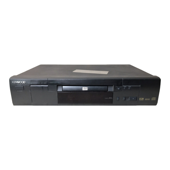
DVD VCD CD PLAYER
DVF-5020
SERVICE MANUAL
This manual is available for repair in the Europe markets. In other market, please refer to service
manual (B51-5583-00).
Power button
(K27-2399-08)
Top cover
(A01-3749-08)
DIGITAL AUDIO OUT
(PCM/BIT STREAM)
CENTER
OPTICAL
COAXIAL
SUB
WOOFER SURROUND
Oscillating module
Pin jack
(W02-2735-08)
(E63-1151-08)
In compliance with Federal Regulations, following are repro-
ductions of labels on, or inside the product relating to laser
product safety.
KENWOOD-Crop. certifies this equipment conforms to DHHS
Regulations No. 21 DFR 1040. 10, Chapter 1, Subchapter J.
DANGER : Laser radiation when open and interlock
defeated.
AVOID DIRECT EXPOSURE TO BEAM
Tray top
(A29-1093-08)
Front cover
(B10-3573-08)
Pin jack
(E63-1149-08)
VIDEO
AUDIO OUT
SURROUND
FRONT
L
OUT
L
L
S VIDEO OUT
R
R/
R
FRONT R
Pin jack
Y/C connector
(E63-1150-08)
(E63-1148-08)
© 1999-9/B51-5580-00 (K/K) 1355
VIRTUAL
STANDBY
SURROUND
AV1
AV2
ConnectorX2
(E40-8598-08)
Caution : No connection of ground line if disassemble
the unit. Please connect the ground line on
rear panel, PCBs, Chassis and some others.
NOTE : Please use the remote controller
for self-diagnosis and tilt adjust-
ment.
Front panel
(A60-1820-08)
OPEN/CLOSE
Leg
(J02-1468-08)
~
AC IN
AC inlet
(E40-8593-08)
70%
Advertisement

Related Manuals for Kenwood DVF-5020


Summary of Contents for Kenwood DVF-5020
- Page 1 PCBs, Chassis and some others. NOTE : Please use the remote controller KENWOOD-Crop. certifies this equipment conforms to DHHS Regulations No. 21 DFR 1040. 10, Chapter 1, Subchapter J. for self-diagnosis and tilt adjust- DANGER : Laser radiation when open and interlock ment.
-
Page 2: Table Of Contents
DVF-5020 CONTENTS / ACCESSORIES Contents CONTENTS / ACCESSORIES ........2 WIRING DIAGRAM ...........33 DISASSEMBLY FOR REPAIR........3 PC BOARD .............. 34 BLOCK DIAGRAM ............14 SCHEMATIC DIAGRAM .......... 39 CIRCUIT DESCRIPTION ..........18 EXPLODED VIEW ............64 ADJUSTMENT ............21 PARTS LIST..............67 ABBREVIATION............22 SPECIFICATIONS ........Back cover VOLTAGE CHART............24... -
Page 3: Disassembly For Repair
DVF-5020 DISASSEMBLY FOR REPAIR 1. Assembling and Disassembling the Casing 1-4 Disassembling the Front Panel and Checking C.B.A.s 1. Release the 3 tabs on the bottom. 2. Release the 2 tabs on the left and right. 1-1 Casing Parts and C.B.A. Positions... - Page 4 DVF-5020 DISASSEMBLY FOR REPAIR 1-6 Checking the Module C.B.A. 2. Release the two tabs on the left and right. 1. Remove the 2 screws. 1-8 Checking the Power Supply C.B.A. 1. Remove the 3 screws. 2. Connect the module C.B.A. to the mother C.B.A. with the extension cables for inspection.
- Page 5 DVF-5020 DISASSEMBLY FOR REPAIR 1-9 Checking the Mother C.B.A. 2. To preserve the quality of the optical pickup replacement parts during transport and installation, the terminals of 1. Remove the 5 screws. the laser diode are short-circuited. After replacing the 2.
- Page 6 DVF-5020 DISASSEMBLY FOR REPAIR 2-3 Lubricating the Loading Base Unit When replacing parts, lubricate the parts maked “xxx” in the diagram Part number Service Tool Grease 410-0013-05 Grease EM-30LG...
- Page 7 DVF-5020 DISASSEMBLY FOR REPAIR 2-4 Static Electricity Countermeasures 2-5 Disassembling the Clamp Base Unit The laser diode inside the traverse unit (optical pickup) can Remove the 2 screws. be damaged by static electricity from your body. Be sure to take static electricity countermeasures when working around the optical pickup.
- Page 8 DVF-5020 DISASSEMBLY FOR REPAIR 2-7 Disassembling the Traverse Unit 2-8 Disassembling the Stepping Motor Unit 1. Remove the 3 screws. 1. Disconnect the flexible cable. 2. Remove the 2 screws. Note Take care when handling the flexible cable because it can be broken by excessive force.
- Page 9 DVF-5020 DISASSEMBLY FOR REPAIR 2-10 Disassembling the Nut Unit 2-12 Assembling the Optical Pickup 1. Remove the screw. 1. Install the optical pickup. Notes Note Take care not ot attach the tilt spring and guide shaft in • The nut unit is not part of the optical pickup.
- Page 10 DVF-5020 DISASSEMBLY FOR REPAIR 3. Insert the pickup FPC into connector FP5201 on the mod- 2-14 Optical Pickup Tilt Adjustment ule C.B.A. 4. Remove the solder from the pickup FPC's soldered short- circuit. 5. Adjust the optical pickup tilt after removing the solder.
- Page 11 DVF-5020 DISASSEMBLY FOR REPAIR Notes • Adjustment is generally unnecessary after replacing other parts of the traverse unit. However, adjust if there is a noticeable degradation in picture quality. • Optical adjustments cannot be made inside the optical pickup. • Adjustment is generally unnecessary after replacing the traverse unit.
- Page 12 DVF-5020 DISASSEMBLY FOR REPAIR 2-15 Disassembling the Intermediate Chassis 2-17 Disassembling the Pulley Gear and Decelera- tion Gear 1. Push the stopper downward, then rotate it until it contacts the Vertical cam. 1. Remove the screw. 2. Release the 2 tabs.
- Page 13 MECHANISM UNIT MODULE C.B.A. MOTHER C.B.A. IC5202 IC2001 IC7001 IC3001 IC4201 FRONT MIXL OPTICAL AUDIO PICK UP PROCESSOR UNIT CONVERTER MIXR (FEP) IC2501 16.9MHz IC4211 OPTICAL DIGITAL SPINDLE DISC SPINDLE SERVO MOTOR DECODER AUDIO CONTROLLER MOTOR CONTROLLER DRIVE (AV DEC) (ODC) (DSC) IC6302...
- Page 14 RF SIGNAL SPINDLE MOTOR DRIVE SIGNAL STEPPING MOTOR DRIVE SIGNAL TRACKING ERROR SIGNAL FOCUS ERROR SIGNAL STEPPING MOTOR UNIT IC5202 IC2001 IC2511 STEPPING MOTOR OPTICAL PICK UP UNIT (FEP) (DSC) (MOTOR DRIVE) VO3- VIN6 PHOTO DETECTOR VIN5 VO3+ VIN1 RDTN TRSDRV-A OPIN4- HEAD...
- Page 15 MODULE C.B.A. MOTHER C.B.A. VIDEO SIGNAL IC3531-16 IC3531-14 IC3531-19 IC3201-29 IC3201-33 IC3001-148*155 2.2Vp-p(20usec./div.) 1.2Vp-p(20usec./div.) 2.2Vp-p(20usec./div.) 0.68Vp-p(20usec./div.) 0.64Vp-p(20usec./div.) 6.0Vp-p(20usec./div.) IC3201-24 IC3201-25 IC3001 1.2Vp-p(20usec./div.) 1.5Vp-p(20usec./div.) (AV DECORDER) IC3531 Y ADJ. Q3211 FL3501 Q3501 Q3502 Q3503 Q3601 Q3602 Q3603 (VIDEO DRIVER) VR3501 L.P.F. YOUT FROM IC6201-80PIN...
- Page 16 AUDIO SIGNAL IC3001-117 6.4Vp-p(10usec./div.) IC4201 IC3001 (AUDIO D/A CONVERTER) IC4301 MIXL Lch OUT A MUT FROM IC4301 IC6201-3PIN MIXR Rch OUT STBDAC FROM IC6201-59PIN SBT1 FROM IC6201-70PIN SBO1 FROM 0.7Vp-p(0.5msec./div.) IC6201-72PIN NRST FROM IC6201-79PIN IC4211 (AUDIO D/A CONVERTER) IC4321 AOUT0 117 FL OUT A MUT FROM...
-
Page 17: Circuit Description
DVF-5020 CIRCUIT DESCRIPTION 1. Optical Pickup Self-Diagnosis and Replacement Procedure The optical pickup self-diagnosis function and tilt adjustment check function have been newly added to this player. When repairing, use the following procedure for effective Self-diagnosis and tilt adjustment. Be sure to use the self-diagnosis function before replacing the optical pickup when "NO DISC" is displayed. As a guideline, you should replace the optical pickup when the value of the laser drive current is more than 50. - Page 18 DVF-5020 CIRCUIT DESCRIPTION 2. Self-Diagnosis Function and Service Modes 2-1 Service Mode Table The service modes can be activated by pressing various button combinations on the player and remote control unit. Player Remote control Application Note buttons unit buttons Displaying the UHF display F_ _ _...
- Page 19 DVF-5020 CIRCUIT DESCRIPTION 2-4 Examples of Repairs Using Error Codes Refer to this section when carrying out repairs. Error display Malfunction example F0** Disc, IC7001 F103 Disc, IC7001 F4FF IC6001 F500 Optical pickup, IC2001, IC5201, IC2511, IC2501 F501 IC2001, IC6201...
- Page 20 DVF-5020 CIRCUIT DESCRIPTION 3. Service Tools and Equipment 3-1 Service Tools and Equipment Table Application Name Number General DVD disc (Include the color bar 75%) Tilt adjustment Hex wrench (ø1.27mm) Inspection Extension cables (power supply C.B.A. to mother C.B.A.) Extension cable(A) Extension cable (module C.B.A.
-
Page 21: Adjustment
DVF-5020 ADJUSTMENT 1. Video Output (Luminance Signal) Adjustment Do this adjustment after replacing a C.B.A. Measurement point Adjustment point Mode Disc Video output terminal VR3501 (mother C.B.A.) Color bar 75% DVD disc (Color bar 75%) Measuring equipment, tools Adjustment value Screwdriver, Oscilloscope 1000mVp-p±20mV... - Page 22 DVF-5020 ADJUSTMENT/ABBREVIATION 3. Video Component Signal (CB) Output Adjustment Do this adjustment after replacing a C.B.A. Measurement point Adjustment point Mode Disc Video output terminal VR3201 (mother C.B.A.) Color bar 75% DVD disc (Color bar 75%) Measuring equipment, tools Adjustment value Screwdriver, Oscilloscope 525mVp-p±11mV...
-
Page 23: Abbreviation
DVF-5020 ABBREVIATION INITIAL/LOGO ABBREVIATIONS INITIAL/LOGO ABBREVIATIONS ETMCLK EXTERNAL M CLOCK R RE READ ENABLE (81MHz/40.5MHz) RFENV RF ENVELOPE ETSCLK EXTERNAL S CLOCK RF PHASE DIFFERENCE OUTPUT (54MHz) (CD-ROM) REGISTER SELECT FBAL FOCUS BALANCE RSEL RF POLARITY SELECT FCLK FRAME CLOCK... -
Page 24: Voltage Chart
DVF-5020 ABBREVIATION/VOLTAGE CHART INITIAL/LOGO ABBREVIATIONS INITIAL/LOGO ABBREVIATIONS VBLANK V BLANKING X CHIP SELECT COLLECTOR POWER SUPPLY XCSYNC X COMPOSITE SYNC VOLTAGE X DATA STROBE VCDCONT VIDEO CD CONTROL (TRACKING XHSYNCO X HORIZONTAL SYNC OUTPUT BALANCE) XHINT XH INTERRUPT REQUEST DRAIN POWER SUPPLY VOLTAGE... - Page 25 DVF-5020 VOLTAGE CHART Ref No. IC2001 MODE STOP PLAY IC2501 Ref No. MODE STOP PLAY IC2501 Ref No. MODE STOP PLAY Ref No. IC2511 MODE STOP PLAY IC2511 Ref No. MODE STOP PLAY IC3001 Ref No. MODE STOP PLAY IC3001 Ref No.
- Page 26 DVF-5020 VOLTAGE CHART IC3061 Ref No. MODE STOP PLAY IC3071 Ref No. MODE STOP PLAY IC3071 Ref No. MODE STOP PLAY Ref No. IC3071 IC3081 MODE STOP PLAY Ref No. IC3281 IC3301 MODE STOP PLAY IC3201 Ref No. MODE STOP...
- Page 27 DVF-5020 VOLTAGE CHART Ref No. IC5202 MODE STOP PLAY Ref No. IC5202 MODE STOP PLAY Ref No. IC5202 MODE STOP PLAY Ref No. IC5202 MODE STOP PLAY IC5202 Ref No. MODE STOP PLAY IC6201 Ref No. MODE STOP PLAY IC6201 Ref No.
- Page 28 DVF-5020 VOLTAGE CHART IC6541 IC6542 Ref No. MODE STOP PLAY IC6561 IC6562 IC6563 Ref No. MODE STOP PLAY IC6581 IC6582 Ref No. MODE STOP PLAY IC6601 Ref No. MODE STOP PLAY Ref No. IC7001 MODE STOP PLAY Ref No. IC7001...
- Page 29 DVF-5020 VOLTAGE CHART 5-3 MOTHER C.B.A. IC3531 Ref No. MODE STOP PLAY Ref No. IC3531 MODE STOP PLAY Ref No. IC4201 MODE STOP PLAY Ref No. IC4201 MODE STOP PLAY Ref No. IC4211 MODE STOP PLAY IC4221 Ref No. MODE...
- Page 30 DVF-5020 VOLTAGE CHART IC4391 Ref No. MODE STOP -8.9 -0.2 -0.2 PLAY -8.9 -0.2 -0.2 IC4391 Ref No. MODE STOP -0.2 -0.2 PLAY -0.2 -0.2 IC4392 Ref No. MODE STOP -8.9 -0.2 -0.2 PLAY -8.9 -0.2 -0.2 IC4392 Ref No.
- Page 31 DVF-5020 VOLTAGE CHART IC6001 Ref No. MODE STOP -31.4 -18.0 -28.8 -28.8 -28.8 PLAY -29.5 -10.1 -24.6 -21.7 -27.0 IC6001 Ref No. MODE STOP -16.2 -21.1 -21.4 -28.5 -28.4 -28.8 -28.8 -28.8 -28.8 -28.8 -28.8 -28.7 -21.4 PLAY -17.5 -14.5 -21.8...
- Page 32 DVF-5020 VOLTAGE CHART 5-4 SCART C.B.A. IC3801 IC3811 Ref No. MODE STOP -12.4 -5.0 -5.0 PLAY -12.7 -5.0 -5.0 IC3812 Ref No. MODE STOP -5.0 PLAY -5.0 Ref No. IC3813 MODE STOP -5.0 PLAY -5.0 IC3821 Ref No. MODE STOP -5.0...
- Page 34 THE STRIPED FRAME INDICATES THE PRIMARY CIRCUIT TO DISTINGUISH CAUTION PS1101 THE PRIMARY FROM THE SECONDARY CIRCUIT. PAY ATTENTION NOT TO RECEIVE AN ELECTRIC SHOCK DURING REPAIR AND SERVICE OF THE PRODUCTS. R1161 W004 POWER SUPPLY C.B.A. W052 C1117 C1121 C1154 IC1101 R1106...
- Page 35 MODULE C.B.A. (1/2) TC3210 TC3205 TC3204 TC3203 TC4016 TC4015 TC4013 TC4012 TC4011 TC4009 TP6251 FL6251 TC4014 C4251 TC3209 TC4010 TP6252 C3076 C6251 C3075 TP6259 TP6202 PS3201 PS4201 RA3004 RA3007 RA3006 RA3008 RA3003 RA3002 RA3001 TP6253 R6541 D6561 TP6204 C6561 C6581 C3006 D6541 FL6252...
- Page 36 MOTHER C.B.A. IC6003 DL6001 D6013 D6014 S6007 S6003 S6005 S6001 S6006 S6002 S6004 53 54 W054 R6011 R6010 R6008 R6057 C6021 R6001 LB6003 R6056 R6002 R6044 LB6004 W203 W226 R6003 R6035 R6049 LB6006 LB6002 R6009 W031 R6055 W207 R6052 LB6007 LB6005 LB6001 R6054...
- Page 37 The DC voltage is an actual reading measured with a high impedance type voltmeter with no signal input. The measurement value may vary depending on the measuring instruments used or on the product. DVF-5020 Y22-8202-71...
- Page 38 (exposed parts are acceptably insulated from the supply DVF-5020 circuit) before the appliance is returned to the The DC voltage is an actual reading measured with a high impedance type voltmeter customer.
- Page 39 The DC voltage is an actual reading measured with a high impedance type voltmeter with no signal input. The measurement value may vary depending on the measuring instruments used or on the product. DTA123JK 2SD1819A UN4213 UN5213 2SB1218A 2SB709A 2SD1328 UPC1093J MA742 UN5212 2SK170 TC7SH08FU BA5983FM TC7S02FU DVF-5020 Y22-8202-71...
- Page 40 The DC voltage is an actual reading measured with a high impedance type voltmeter with no signal input. The measurement value may vary depending on the measuring instruments used or on the product. DVF-5020 Y22-8202-71...
- Page 41 The DC voltage is an actual reading measured with a high impedance type voltmeter with no signal input. The measurement value may vary depending on the measuring instruments used or on the product. DVF-5020 Y22-8202-71...
- Page 42 The DC voltage is an actual reading measured with a high impedance type voltmeter with no sig- nal input. The measurement value may vary depending on the measuring instruments used or on the product. DVF-5020 Y22-8202-71...
- Page 43 To reduce the risk of electric shock, leakage-current or resistance measurements shall be carried out (exposed parts are DVF-5020 acceptably insulated from the supply circuit) before the appliance is returned to the customer.
- Page 44 The DC voltage is an actual reading measured with a high impedance type voltmeter with no sig- nal input. The measurement value may vary depending on the measuring instruments used or on the product. DVF-5020 Y22-8202-71...
- Page 45 DVF-5020 The DC voltage is an actual reading measured with a high impedance type voltmeter with no signal input. The measurement value may vary depending on the measuring instruments used or on the product.
- Page 46 CAUTION: For continued safety, replace safety critical components only with manufacturer's recommended parts (refer to parts The DC voltage is an actual reading measured with a high impedance type voltmeter with DVF-5020 list). indicates safety critical components. For continued protection against risk of fire, replace only with same type and rating no signal input.
- Page 47 The DC voltage is an actual read- ing measured with a high imped- ance type voltmeter with no signal input. The measurement value may vary depending on the mea- DVF-5020 suring instruments used or on the product. Y22-8202-71...
- Page 48 (exposed parts are acceptably insulat- ed from the supply circuit) before the appliance is returned to the customer. DVF-5020 The DC voltage is an actual reading measured with a high impedance type voltmeter with no signal input.
- Page 49 FRONT SWITCH, HEADPHONE JACK, HEDPHONE VOLUME AND POWER SWITCH DVF-5020 Y22-8202-71...
- Page 50 DVF-5020 EXPLODED VIEW (DVD MECHANISM) Parts with exploded numbers larger than 700 are not supplied.
- Page 51 DVF-5020 EXPLODED VIEW (DVD MECHANISM) Parts with exploded numbers larger than 700 are not supplied.
- Page 52 JK3541 JK4501 JK4502 JK4771 IC4781 DL6001 OPEN/ CLOSE STOP SKIP PAUSE SKIP PLAY S6007 S6003 S6005 S6001 S6006 S6002 POWER B9 B9 S6401 N09-5149-08 N09-5150-08 N09-5150-08 N09-5153-08 3x12 N09-5154-08 602x 3x20 N09-5155-08 3x25 N09-5156-08 2.6x10 N09-5157-08 3x10 N09-5158-08 DVF-5020 (E)
-
Page 53: A70-1353-08
Parts No. Description Description Ref. No Parts No. Parts marks ress nation Parts nation marks ress C1141 C90-3874-08 ELECTRO 150UF 35WV DVF-5020 C1143 CE04KW1E330M ELECTRO 33UF 25WV C1151 C90-3922-08 ELECTRO 390UF 25WV A01-3749-08 TOP COVER VGM1591 C1153 CE04KW1E221M ELECTRO 220UF... - Page 54 New Parts New Parts Parts without Parts No. are not supplied. Parts without Parts No. are not supplied. Les articles non mentionnes dans le Parts No. ne sont pas fournis. Les articles non mentionnes dans le Parts No. ne sont pas fournis. Teile ohne Parts No.
- Page 55 New Parts New Parts Parts without Parts No. are not supplied. Parts without Parts No. are not supplied. Les articles non mentionnes dans le Parts No. ne sont pas fournis. Les articles non mentionnes dans le Parts No. ne sont pas fournis. Teile ohne Parts No.
- Page 56 New Parts New Parts Parts without Parts No. are not supplied. Parts without Parts No. are not supplied. Les articles non mentionnes dans le Parts No. ne sont pas fournis. Les articles non mentionnes dans le Parts No. ne sont pas fournis. Teile ohne Parts No.
- Page 57 New Parts New Parts Parts without Parts No. are not supplied. Parts without Parts No. are not supplied. Les articles non mentionnes dans le Parts No. ne sont pas fournis. Les articles non mentionnes dans le Parts No. ne sont pas fournis. Teile ohne Parts No.
- Page 58 New Parts New Parts Parts without Parts No. are not supplied. Parts without Parts No. are not supplied. Les articles non mentionnes dans le Parts No. ne sont pas fournis. Les articles non mentionnes dans le Parts No. ne sont pas fournis. Teile ohne Parts No.
- Page 59 New Parts New Parts Parts without Parts No. are not supplied. Parts without Parts No. are not supplied. Les articles non mentionnes dans le Parts No. ne sont pas fournis. Les articles non mentionnes dans le Parts No. ne sont pas fournis. Teile ohne Parts No.
- Page 60 New Parts New Parts Parts without Parts No. are not supplied. Parts without Parts No. are not supplied. Les articles non mentionnes dans le Parts No. ne sont pas fournis. Les articles non mentionnes dans le Parts No. ne sont pas fournis. Teile ohne Parts No.
- Page 61 New Parts New Parts Parts without Parts No. are not supplied. Parts without Parts No. are not supplied. & Les articles non mentionnes dans le Parts No. ne sont pas fournis. Les articles non mentionnes dans le Parts No. ne sont pas fournis. Teile ohne Parts No.
- Page 62 New Parts New Parts Parts without Parts No. are not supplied. Parts without Parts No. are not supplied. Les articles non mentionnes dans le Parts No. ne sont pas fournis. Les articles non mentionnes dans le Parts No. ne sont pas fournis. Teile ohne Parts No.
- Page 63 New Parts Parts without Parts No. are not supplied. ¡ Les articles non mentionnes dans le Parts No. ne sont pas fournis. Teile ohne Parts No. werden nicht geliefert. Desti- Add- Ref. No Parts No. Description Parts marks ress nation QR4591 UN2211 TRANSISTOR...
- Page 64 KENWOOD ELECTRONICS GULF FZE KENWOOD ELECTRONICS U.K. LIMITED P.O.Box 61318, Jebel Ali, Dubai, U.A.E. KENWOOD House, Dwight Road, Watford, Herts., WD1 8EB., United Kingdom KENWOOD ELECTRONICS SINGAPORE PTE LTD. KENWOOD ELECTRONICS BELGUM N.V. No. 1 Genting Lane #02-02, KENWOOD Building, Singapore, 349544 Meachelsesteenweg 418, B-1930 Zaventem, Belgium KENWOOD ELECTRONICS (MALAYSIA) SDN BHD.