
Related Manuals for Sharp LMV Series


Summary of Contents for Sharp LMV Series
- Page 1 OPERATION & PARTS MANUAL Sharp Industries, Inc. 3501 Challenger Street Torrance, CA 90503 (310) 370-5990 Fax: (542-6162) www.sharp-industries.com...
- Page 2 2. After disconnecting the power, remove cover on the motor. The diagram below should appear on the inside. If in doubt about the electrical wiring, please consult a qualified electrician or Sharp Industries, Inc. for advice. 3. After making the connections as illustrated below, check that all connections are...
- Page 3 TWIN COOLING FAN WIRING DIAGRAM 1. Warning: Disconnect power source before starting installation. 2. Caution: Follow wiring instruction carefully. 3. For trouble shooting, use a meter to check the current. Do not use the 440V current to check the fan individually. 4.
-
Page 4: Table Of Contents
CONTENTS Forward ......................... 1 Safety Rules and Regulations ................1 ......... 2 MODEL LMV VERTICAL VARIABLE SPEED MILL ......................2 Specifications ......................... 2 Uses ......................3 Machine Parts ..................7 Headstock Cooling System ......................8 Lubrication Operation Instructions: ......................10 Headstock ...................... -
Page 5: Forward
4. Caution should be taken when removing chips from work surface. 3. Notice: Retrofitting the Sharp Mill with a CNC control, such as Sony, AcuTire, Anilam or other similar controls without the installation of an approved auto-lube system will void the warranty on that machine. -
Page 6: Model Lmv Vertical Variable Speed Mill
SHARP VARIABLE SPEED MILLING MACHINE 1. Specifications: STANDARD SPECIFICATION INCH SPECIFICATION INCH Spindle speed 50HZ 50-3750 rpm WORK TABLE 60HZ 60-4500 rpm Working area of table 42 x 9 Machine Net Weight 1.01 kg Table Travel Saddle Travel Knee Travel... -
Page 7: Machine Parts
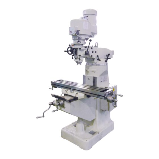
3. Machine parts: 1. Headstock: Power Feed Engagement Crank (I) High/Low Lever (J) Speed Selector (G) Quill Feed Lever (H) Brake Quill Feed Selector (C) Micrometer Adjustment Feed Nut (K) Reverse Knob (D) Quill Lock Feed Handwheel Feed Control Lever (F) - Page 8 DVS HEAD Emergency Stop Speed Meter Forward/Reverse Switch Speed Knob Brake...
- Page 9 2. Machine Body: 1. Columns, Turret, and Ram: Adaptor Lock Bolts (B) Vertical Adjusting Worm Ram Lock Ram (F) Turret (D) Column Gib Bolt (I) Figure 4...
- Page 10 2. Tables, Saddle, and Knee: Vertical Travel Stop (A) Work Table Lock (J) Saddle (C) Work Table (H) Table Stop (B) Saddle Lock Knee (L) Ball Crank Handle (I) Lever (D) Knee Lock Lever (G) Knee Elevating Lever (F) Ball Crank Handle (K) Figure 5...
-
Page 11: Headstock Cooling System
4. Headstock Cooling System: The variable speed headstock is equipped with a unique cooling system. Two fans have been installed outside of the cover between the front and rear speed change wheels. The purpose of the fans are to dissipate the heat build up between the belt and the speed change wheel, and prolong the life of the mill. -
Page 12: Lubrication
5. Lubrication: 1. Head: Position Type Lubricant Frequency Function One Shot Every Grease Shell Tonna 32 Motor Shaft 3 Months Grease Shell Tonna 32 As Needed ** Bull Gear Bull Gear Oil Cup Shell Tonna 32 Twice a Week Bearing Shaft Worm Gear Oil Cup Shell Tonna 32... - Page 13 2. Table, Saddle, and Knee The ways, saddle, knee and leadscrews are oiled by means of Position a manually operated pump, located on the back side of knee. Frequency 2 pumps 3 to 5 times daily Lubricant Shell Tonna 33 Figure 8...
-
Page 14: Headstock
6. Operation: 1. Headstock: Power to the motor is controlled by a three way switch, forward, reverse, and off (Fig. 9). When the high-low speed change lever (Fig. 3 (J), Page 3) is in high gear position and the switch is in FOR., the spindle rotation is clockwise. - Page 15 Manual Feed: The manual feed lever is located on the right side of the headstock (Fig. 3 (H), Page 3). This lever controls the vertical movement of the spindle. For the operator’s convenience the lever can be adjusted as needed. Note: in manual feed, the feed control handle “F”...
- Page 16 Automatic feed: Procedure for using this function is: Loosen the quill lock “L” (Fig. 3, Page 3) Place the power feed transmission lever “I” (Fig. 3, page 3) in the “IN” position. Place feed speed lever “C” (Fig. 3, Page 3) in the desired position.
- Page 17 g. Spindle speed change: The speed of spindle is controlled by a set of sliding belt pulleys and a counter shaft gear. There are two options (High and low). High gear is for RPM from 500 to 3,000 and low gear for RPM from 60 and 580. When high-low lever “J”...
- Page 18 Tilting the headstock (Fig. 14): To tilt the head up or down, evenly loosen the three adapter locking bolts (P) and move to desired angle using adjusting worm shaft “Q”. Re-tighten the adapter bolts. NOTE: do not remove adapter bolts. Cross tilting the headstock (Fig.
-
Page 19: Mill Body
2. Machine Body Operation: 1. Ram movement (Fig. 17): To move ram in or out, loosen Ram lock levers “A” and move to desired position using handle “B” and retighten levers. To swivel ram, loosen the four bolts “C”, move to desired position and retighten bolts “C”. - Page 20 2. Setting handwheel dials to zero (Fig. 18): a. Loosen lock ring “D”. b. Turn dial “E” to zero and tighten lock ring “D”. 3. Locking the table, saddle, and knee: To increase the stability of the mill and maintain a good workpiece finish, all non-feeding surfaces should be locked down.
-
Page 21: Unpacking, Moving, And Floor Space
7. Unpacking, moving, and floor space: a. Methods of moving machine: Prior to unpacking or removing from skid, the machine should be moved by the use of a forklift or reinforced cable (Fig. 20 & 21). Removal from the skid and any further movement of the machine should be done by the use of a reinforced cable or by the eye bolt located in the top of the ram. - Page 23 b. Unpacking: To protect the machine while in transit it is necessary to cover it with a rust proof coating and a crate or plastic wrapping. In the event, there is damage due to moisture, please contact our agent or the transporter. After unpacking, make sure all tools and accessories are intact.
-
Page 25: Alignment
7. Machine Alignment: Maintaining close tolerances and proper alignment of the machine is critical to producing quality-machining results. Please see the following table of Precision Inspection. -
Page 29: Trouble Shooting
8. Trouble Shooting: 1. Removing Motor (Fig. 25): While running motor reduce speed to 60 RPM. This will lower the stationary motor vari-disc to its lowest position. Temporarily disconnect the power source. Remove motor pulley cover “B” under the motor shaft, remove grease fitting. - Page 30 Figure 25...
- Page 31 2. Replacing the Speed Change Belt Refer to steps a. to g. on page 24 for removing motor. Remove drawbar. Remove bolts “J” from bearing housing “K”. Use 2 of the bolts to push housing off of the housing “T”. Remove the 2 bolts “L”...
- Page 32 Figure 26...
- Page 33 3. Brake Block Replacement (Fig. 27): Refer to steps a. to g. on page 24 and steps b. to g. on page 26. Remove the four bolts “V” (Fig. 28) so housing “T1” can be removed. It may be necessary to use a soft mallet. (Housing “T1” and “R” are pinned together).
- Page 34 4. Replacing Timing Belt: Follow disassembling procedures outlined in steps a. to g. on page 24 and steps b. to g. on page 26 and steps b. on page 28. Change the timing belt as shown in Fig. 28. Reverse above order to re-assemble. Figure 28...
- Page 35 5. Adjusting leadscrew backlash: A. Y-axis backlash adjustment: Move saddle to the middle of its travel. Remove 4 bolts “I” on bearing bracket “G”. Lock saddle and turn hand crank “F” clockwise to separate bracket “G” from the knee. Unlock saddle and move screw until adjusting tool fits into the space. Use the large end of the tool to loosen the lock nut “J”...
- Page 36 B. X axis backlash adjustment; Move the work table to the center of the saddle. Insert large end of adjusting tool into the left side of the saddle and turn lock nut “J” counter clockwise approximately one turn. Using small end of tool tighten adjusting nut “K”. After adjusting nut “K”, use large end of tool to re-tighten lock nut “J”.
- Page 37 6. Adjusting Gibs: After a period of time the gibs may become loose or worn and may need to be adjusted to maintain the integrity of the mill. A. Table Gib (Fig. 32): The table gib is located between the saddle seat and the table dovetail. a.
- Page 38 B. Saddle Gib (Fig. 33) The saddle gib is located between the left side of the saddle and knee dovetail, and it can be adjusted as follows: a. Loosen saddle lock “A”. b. Move saddle to the front of knee. c.
- Page 39 C. Knee Gib (Fig. 34) The knee gib is located between the left side of knee and column dovetail, and it can be adjusted as follows: a. Loosen knee clamp (Fig. 5, Page 5). b. Remove wiper holder “Q”. c. Clean and lubricate sideways. d.
- Page 40 E. Collet Alignment Screw Replacement: a. First mark the location of nose piece “B” to its position to quill “A”. b. Remove set screw “C” located on nose piece. Remove nose piece by inserting an adjustable spanner in two holes in the bottom of nose piece. c.
-
Page 41: Maintenance
10. Maintenance “Maintenance is more important than repair, and repair is better than purchase.” The life of a machine can be greatly reduced if it has been properly maintained and operated. The result will be premature wear, inability to hold tolerance and poor finish on the workpiece. -
Page 42: Feedrate Cutting Speeds
11. Notice: 1. Machine Operation: Machine must be installed on a solid base. Be sure the machine base and surface have proper contact before tightening anchor bolts. Be sure motor voltage conforms to the source voltage and properly grounded. Turn off machine before changing gears. Be sure cutter or tool is clear of the workpiece before starting or stopping the machine. -
Page 43: Remarks
PARTS LIST... - Page 44 DVS HEAD PARTS 1 KEY PART NUMBER DESCRIPTION QUANTITY H-014 SHIFT CRANK H-097 GEAR SHIFT PLUNGER H-262 COMPRESSION SPRING H-284 BLACK PLASTIC BALL H-502 GEAR HOUSING H-504 BELT HOUSING (BOTTOM) H-505 BELT HOUSING (UPPER) H-727 RPM DISPLAY HOUSING H-728 SWITCH HOUSING H-729 HOUSING PLATE E-22S38B-EVS...
- Page 46 KEY PART NUMBER DESCRIPTION QUANTITY H-149 DRAWBAR WASHER H-250 SOCKET SET SCREW H-290 BEARING LOCK NUT H-291 LOCK WASHER H-505 BELT HOUSING (UPPER) H-515 TOP BEARING CAP H-516 WAVE WASHER H-517 BALL BEARING H-522 BALL BEARING H-527 H-528 MOTOR H-529 HEX HEAD SCREW H-530 SPRING WASHER...
- Page 47 DVS HEAD PARTS 2...
- Page 48 Initial Setting Current Setting Initial Setting Current Setting 102.0 1.03...
- Page 51 PARTS NO. DESCRIPTION REMARKS TM-H001 QUILL HOUSING TM-H002 GEAR HOUSING TM-H003 GEAR HOUSING COVER TM-H004 BELT HOUSING TM-H005 SPINDLE PULLEY TM-H006 MOTOR PULLEY TM-H007 TIMING BELT PULLEY TM-H008 TIMING BELT PULLEY FLANGE TM-H012 BACK GEAR SHIFTER FORK TM-H013 SPINDLE PULLEY BEARING SLEEVE TM-H019 MOTOR PULLEY WASHER DRAWBAR KNOB (NT 30 1/2”...
- Page 52 PARTS NO. DESCRIPTION REMARKS TM-H131 MOTOR LOCK NUT TM-H132 MOTOR LOCK NUT HANDLE TM-H133 MOTOR MOUNTING STUDS TM-H134 MOTOR MOUNTING STUDS WASHER TM-H149 DRAWBAR WASHER (R8) TM-H150 SOCKET SET SCREW TM-H157 QUILL MICRO STOP NUT (IN) TM-H165 SPINDLE (NT 30) TM-H166 SPINDLE (R8) TM-H167...
- Page 53 PARTS NO. DESCRIPTION REMARKS 18VH-H090 QUILL (NT 40) 18VH-H094 DRAWBAR KNOB NUT (NT 40) 18VH-H096 DRAWBAR (NT 40) 18VH-H097 DRAWBAR (NT 40)
- Page 54 PARTS NO. DESCRIPTION REMARKS TM-H004 BELT HOUSING TM-H013 SPINDLE PULLEY BEARING SLEEVE TM-H084 CAM RING TM-H086 SPINDLE CLUTCH CAM RING PIN TM-H087 BRAKE BLOCK TM-H088 BRAKE RING SCREW TM-H089 BRAKE LOCK STUD TM-H091 BRAKE LOCK WASHER TM-H092 BRAKE LOCK HANDLE TM-H093 BRAKE LOCK PIN TM-H284...
- Page 56 PARTS NO. DESCRIPTION REMARKS TM-H001 BELT HOUSING TM-H009 SPINDLE PULLEY BEARING SLEEVE TM-H010 CAM RING TM-H014 SPINDLE CLUTCH CAM RING PIN TM-H016 BRAKE BLOCK TM-H017 BRAKE RING SCREW TM-H018 BRAKE LOCK STUD TM-H021 BRAKE LOCK WASHER TM-H029 BRAKE LOCK HANDLE TM-H032 BRAKE LOCK PIN TM-H033...
- Page 57 PARTS NO. DESCRIPTION REMARKS TM-H109 BEVEL GEAR THRUST SPACER TM-H110 FEED REVERSE BEVEL GEAR TM-H111 FEED WORM SHAFT THRUST WASHER TM-H112 FEED REVERSE CLUTCH TM-H114 FEED WORM SHAFT BUSHING TM-H115 FEED REVERSE BEVEL GEAR TM-H116 REVERSE CLUTCH ROD TM-H117 REVERSE KNOB TM-H118 HANWHEEL CLUTCH TM-H125...
- Page 58 PARTS NO. DESCRIPTION REMARKS TM-H SCREW TM-H BLACK PLASTIC BALL HANDLE TM-H BUSHING TM-C TABLE LOCK BOLT HANDLE...
- Page 60 PARTS NO. DESCRIPTION REMARKS TM-H001 QUILL HOUSING TM-H010 OVERLOAD CLUTCH TRIP LEVER TM-H011 FEED GEAR SHIFTER FORK TM-H014 SHIFT CRANK TM-H015 CLUSTER GEAR COVER TM-H016 SPRING COVER TM-H0171 FEED TRIP BRACKET TM-H018 CLUTCH ARM COVER TM-H033 PINION SHAFT HUB SLEEV TM-H036 QUILL STOP KNOB TM-H037...
- Page 61 PARTS NO. DESCRIPTION REMARKS TM-H157 QUILL MICRO STOP NUT TM-H190 SPECIAL HEX NUT TM-H191 SPECIAL HEX NUT TM-H262 SPRING TM-H283 SPRING TM-H284 BLACK PLASTIC BALL TM-H322 MICROMETER SCALE TM-H333 BLACK PLASTIC BALL HANDLE...
- Page 63 PARTS NO. DESCRIPTION REMARKS TM-H002 GEAR HOUSING TM-H003 GEAR HOUSING COVER TM-H004 BELT HOUSING TM-H012 BACK GEAR SHIFTER FORK TM-H014 SHIFT CRANK TM-H95 COUNTER SHAFT TM-H96 COUNTER SHAFT GEAR TM-H97 GEAR SHAFT PLUNGER TM-H152 BACK GEAR SHAFT BUSHING TM-H153 BACK GEAR SHAFT CRANK TM-H284 BLACK PLASTIC BALL TM-H334...
- Page 65 PARTS NO. DESCRIPTION REMARKS TM-H065 QUILL LOCK SLEEVE TM-H066 QUILL LOCK SLEEVE TM-H067 QUILL LOCK BOLT TM-H140 WORM GEAR TM-H141 WORM SHAFT TM-H143 SOCKET SET SCREW TM-H144 GEAR...
- Page 67 PARTS NO. DESCRIPTION REMARKS TM-C069 DIAL LOCK NUT TM-C074 DIAL HOLDER TM-C078 DIAL WITH 200 DRADUATIONS TM-C179 DIAL HOLDER TM-C080 HAND WHEEL TM-C108 LOCK SCREW TM-C109 SCREW ADJUSTING NUT TM-C110 FEED NUT BRACKET TM-C112 LONGITUDINAL FEED NUT B311-A LONGITUDINAL FEED SCREW TM-C117 BEARING SPACER TM-C118...
- Page 69 PARTS NO. DESCRIPTION REMARKS TM-C050 KNEE TM-C105 SADDLE TM-C114 TABLE TM-C119 SADDLE-TABLE GIB TM-C120 TABLE LOCK PLUNGER TM-C121 TABLE LOCK BOLT TM-C122 TABLE LOCK BOLT HANDLE TM-C123 TABLE STOP BRACKET TM-C125 TABLE STOP PIECE TM-C126 STOP PIECE T-BOLT TM-C129 LEFT HAND KNEE-SADDLE WIPER HOLDER TM-C130 RIGHT HAND KNEE-SADDLE WIPER TM-C131...
- Page 71 PARTS NO. DESCRIPTION REMARKS TM-C002 ELEVATING SCREW HOUSING TM-C003 ELEVATING SCREW HOUSING TM-C050 KNEE TM-C051 SOCKET HD CAP SCREW TM-C057 WASHER TM-C059 BEVEL GEAR TM-C069 DIAL LOCK NUT TM-C074 DIAL HOLDER TM-C075 CROSS FEED SCREW TM-C077 CROSS FEED BEARING BRACKET TM-C078 DIAL WITH 200 GRADUATIONS TM-C080...
- Page 73 PARTS NO. DESCRIPTION REMARKS TM-C028 HANDLE TM-C051 SOCKET HD CAP SCREW TM-C057 WASHER TM-C059 BEVEL GEAR TM-C060 BEVEL PINION TM-C063 GEAR SHAFT FOR KNEE TM-C064 BEARING CUP TM-C065 BEARING RETAINER RING TM-C068 DIAL HOLDER TM-C069 DIAL LOCK NUT TM-C070 GEAR SHAFT CLUTCH INSERT TM-C071 ELEVATING CRANK TM-C336...
- Page 75 PARTS NO. DESCRIPTION REMARKS TM-C222 UPPER WORM SPACER TM-C224 TM-C225 RAM ADAPTER TM-C226 VERTICAL ADJUSTING WORM TM-C227 VERTICAL ADJUSTING WORM SHAFT TM-C232 WORM THRUST WASHER TM-C254 TURRET TM-H144 GEAR...
- Page 77 PARTS NO. DESCRIPTION REMARKS TM-C219 HEAD ROTATING STOP PIN TM-C220 STOP PIN BASE TM-C224 TM-C225 RAM ADAPTER TM-C228 ADAPTER PIVOT STUD TM-C230 RAM LOCK BOLT TM-C231 RAM PINION TM-C233 RAM LOCK BOLT HANDLE TM-C234 ADJUSTING BOLT-GIB TM-C236 SCALE TM-C237 RAM PINION HANDLE TM-C238 RAM PINION SCREW TM-C254...
- Page 79 PARTS NO. DESCRIPTION REMARKS VH-H503 GEAR HOUSING PLATE VH-H504 BELT HOUSING (BOTTOM) VH-H505 BELT HOUSING (UP) VH-H506 STUDS VH-H507 GEAR HOUSING VH-H515 TOP BEARING CAP VH-H520 VH-H521 ADJ DRIVEN VARI-DISC ASSEMBLY VH-H523 SLIDING HOUSING VH-H525 STATIONARY DRIVEN VARI-DISC VH-H526 STATIONARY MOTOR VARI-DISC VH-H528 MOTOR VH-H531...
- Page 80 PARTS NO. DESCRIPTION REMARKS VH-H596 SPEED CHANGE PLATE VH-H597 SPEED CHANGE PLATE PIVOT STUD VH-H599 WASHER VH-H602 SPEED CHANGE CHAIN STUD VH-H605 SPEED CHANGE CHAIN DRUM VH-H607 WORM GEAR SHAFT SUPPORTER VH-H609 SPEED CHANGER WORM GEAR VH-H610 BRONZE BEARING VH-H611 LOCK SCREW VH-H613 SPEED CHANGE HOUSING...
- Page 82 PARTS NO. DESCRIPTION REMARKS VH-H503 GEAR HOUSING PLATE VH-H504 BELT HOUSING (BOTTOM) VH-H505 BELT HOUSING (UP) VH-H507 GEAR HOUSING VH-H510 OIL PLUG VH-H515 TOP BEARING CAP VH-H521 ADJ DRIVEN VARI-DISC ASSEMBLY VH-H523 SLIDING HOUSING VH-H525 STATIONARY DRIVEN VARI-DISC VH-H541 DRAWBAR (R8) VH-H545 BRAKE SHOE VH-H547...
- Page 83 PARTS NO. DESCRIPTION REMARKS TM-H607 WORM GEAR SHAFT SUPPORTER TM-H613 SPEED CHANGE HOUSING TM-H616 WORM TM-H617 SPEED CONTROL SHAFT TM-H621 BRONZE BEARING TM-H622 SPEED CHANGE HANDWHEEL TM-H624 HANDLE TM-H092 BRAKE LOCK HANDLE TM-H093 BRAKE LOCK PIN TM-H284 BLACK PLASTIC BALL...