Mitsubishi Electric PAR-21MAA Manual
Hide thumbs
Also See for PAR-21MAA:
- Instruction book (146 pages) ,
- Installation manual (104 pages) ,
- Technical manual (76 pages)
Table of Contents
Advertisement
1 1 1 1 1 . Advantage of New MA Remote Controller ......................................................................... 2
1. Weekly Timer ..................................................................................................................... 2
2. Easy Maintenance Function (Only for Power Inverter Mr. SLIM) ....................................... 2
3. New Display ....................................................................................................................... 3
3.1 Dot Liquid Crystal Display (LCD) ....................................................................................................................... 3
3.2 Multi-language Display ....................................................................................................................................... 3
4. The Other Functions .......................................................................................................... 3
4.1 Temperature Range Limit Setting ....................................................................................................................... 3
4.2 Auto Off Timer .................................................................................................................................................... 3
4.3 Simple Operation Lock ....................................................................................................................................... 3
2 2 2 2 2 . New Functions ...................................................................................................................... 4
3 3 3 3 3 . Appearance ........................................................................................................................... 5
1. Display Section .................................................................................................................. 5
2. Operation Section .............................................................................................................. 5
4 4 4 4 4 . Easy Maintenance Function (Only for Power Inverter Mr. SLIM) ..................................... 6
1. Maintenance Mode Operating Method .............................................................................. 6
2. Guide for Operation Condition ........................................................................................... 8
Check Points .............................................................................................................................................................. 8
5 5 5 5 5 . How to Select Functions of remote controller ................................................................. 10
1. Function Items ................................................................................................................. 10
2. Flowchart of Function Setting .......................................................................................... 11
3. Screen Structure for Function Setting ............................................................................. 12
4. Function Setting Mode ..................................................................................................... 14
4.1 Change Language ............................................................................................................................................ 14
4.2 Function Setting ............................................................................................................................................... 16
4.2.1 Operaton Lock (Operation Function Limit Setting) ............................................................................... 16
4.2.2 Auto Mode Setting ................................................................................................................................ 18
4.2.3 Temperature Range Limit Setting ......................................................................................................... 20
4.3 Basic Functions Setting .................................................................................................................................... 22
4.3.1 Remote Controller Main/Sub Setting .................................................................................................... 22
4.3.2 Timer function setting (Weekly timer/Auto off timer/Simple timer) ........................................................ 23
4.3.3 Contact Number Setting for Error Situation .......................................................................................... 36
4.4 Display Change Setting .................................................................................................................................... 38
4.4.1 Temperature Display °C/°F Setting ....................................................................................................... 38
4.4.2 Inlet air Temperature Display Setting .................................................................................................... 39
4.4.3 Automatic Cooling/Heating Display Setting .......................................................................................... 40
6 6 6 6 6 . Unit Function Setting by the Remote Controller (for Mr. SLIM) ..................................... 42
7 7 7 7 7 . Test Run by the Remote Controller (for Mr. SLIM) .......................................................... 45
1. Points to be Checked before Test Run ............................................................................. 45
2. Test Run using the Remote Controller ............................................................................. 45
8 8 8 8 8 . Self-Diagnosis by the Remote Controller (for Mr. SLIM) ................................................. 46
1.1 When a Problem Occurs During Operation ...................................................................................................... 46
1.2 Self-Diagnosis During Maintenance or Service ............................................................................................... 46
1.3 Remote Controller Diagnosis ........................................................................................................................... 47
2. Error Code List ................................................................................................................ 48
2.1 A-Control Error Codes (E) ................................................................................................................................ 48
2.2 A-Control Error Codes (F/P) ............................................................................................................................. 48
2.3 A-Control Error Codes (U) ................................................................................................................................ 49
9 9 9 9 9 . Monitoring the Operation Data by the remote Controller (for Mr. SLIM) ....................... 50
2. Request Code List ........................................................................................................... 51
2.1 Detail Contents in Request Code ..................................................................................................................... 55
0 0 0 0 0 . System Control (for Mr. SLIM) ........................................................................................... 60
1. One-Remote Controller (Standard) Operation ................................................................. 62
1.1 Wired Remote Controller .................................................................................................................................. 62
1.2 Wireless Remote Controller ............................................................................................................................. 62
1.3 Wired Remote Controller or Wireless Remote Controller Receiver Built into Indoor Unit ................................ 62
2. Two-Remote Controller Operation ................................................................................... 63
2.1 When Two Wired Remote Controllers are Used ............................................................................................... 63
2.2 When Two Wireless Remote Controllers are Used .......................................................................................... 63
2.3 When One Wired and One Wireless Remote Controller are Used .................................................................. 63
Systems (2 to 16)) ........................................................................................................... 64
- - - - - . External Dimensions .......................................................................................................... 65
CONTENTS
1
Advertisement
Table of Contents

Related Manuals for Mitsubishi Electric PAR-21MAA


Summary of Contents for Mitsubishi Electric PAR-21MAA
-
Page 1: Table Of Contents
CONTENTS 1 1 1 1 1 . Advantage of New MA Remote Controller ................. 2 1. Weekly Timer ........................2 2. Easy Maintenance Function (Only for Power Inverter Mr. SLIM) ........2 3. New Display ........................3 3.1 Dot Liquid Crystal Display (LCD) ........................3 3.2 Multi-language Display ............................ -
Page 2: 1 1 1 1 . Advantage Of New Ma Remote Controller
1 1 1 1 1 . Advantage of New MA Remote Controller 1.Weekly Timer The built-in weekly timer enables you not only to make on/off settings but also temperature settings. Up to eight patterns can be set for each day of the week. Saves you money TIME SUN and space because... -
Page 3: New Display
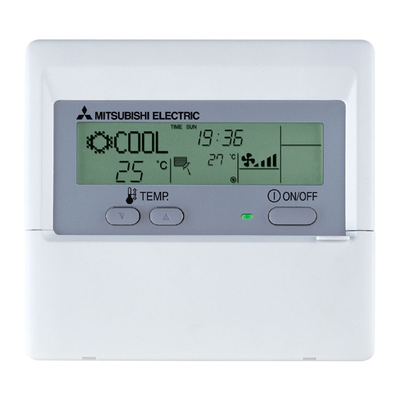
3.New Display Various information is displayed and conveyed clearly, enabling more accurate operation of the air conditioner. 3.1 Dot Liquid Crystal Display (LCD) G Display example [Operation mode] The dot liquid crystal display enables quick understanding of the operation Dot liquid crystal display state. -
Page 4: 2 2 2 2 . New Functions
2 2 2 2 2 . New Functions Available when connect Go to page Power INV Non INV Function Description R410A R407C Easy maintenance function Displays information necessary for maintenance. Below information for easy maintenance of air-condi- tioner can be displayed. •... -
Page 5: 3 3 3 3 . Appearance
Set Time buttons Check button (Clear button) Back MENU ON/OFF FILTER Ahead BACK MONITOR/SET CHECK TEST Airflow Up/Down button PAR-21MAA CLOCK OPERATION Timer On/Off button CLEAR (Set Day button) Louver button Operation button) To preceding operation Opening the number. door. -
Page 6: 4 4 4 4 . Easy Maintenance Function (Only For Power Inverter Mr. Slim)
4 4 4 4 4 . Easy Maintenance Function (Only for Power Inverter Mr. SLIM) G Reduces maintenance work drastically. G Enables you to check operation data of the indoor and outdoor units by remote controller. Furthermore, use of maintenance stable-operation control that fixes the operating frequency, allows smooth inspection, even for inverter models. - Page 7 G Data measurement When the operation is stabilized, measure operation data as explained below. (4) Press the [TEMP] buttons ( ) to select the desired refrigerant address. [Screen B] (5) Select the type of data to be displayed. After selecting, go to step (6). Compressor information button MENU...
-
Page 8: Guide For Operation Condition
2. Guide for Operation Condition Check Points Enter the temperature differences between 5, 4, 7 and 8 into Inspection item Result the graph given below. Breaker Good Retightened Operation state is determined according to the plotted areas on Terminal block Outdoor Unit Good Retightened... -
Page 10: 5 5 5 5 . How To Select Functions Of Remote Controller
5 5 5 5 5 . How to Select Functions of remote controller 1. Function Items The setting of the following functions can be changed using the function selection mode. Item Setting content • Display in multiple languages is possible 1. -
Page 11: Flowchart Of Function Setting
Change Language TEMP. ON/OFF MENU ON/OFF FILTER BACK MONITOR/SET CHECK TEST PAR-21MAA CLOCK OPERATION CLEAR Item3 Operation lock setting is not used. Function (Initial setting value) selection Operation lock setting is except On/Off buttons. Operation lock setting is All buttons. -
Page 12: Screen Structure For Function Setting
3. Screen Structure for Function Setting Description of each screen • Remote controller function selection screen : Used to set the timer function and operation limit function, etc. • Day of the week/time setting screen : Used to set the current day of the week and time. •... -
Page 14: Function Setting Mode
4. Function Setting Mode 4.1 Change Language The language that appears on the dot display can be selected. The following languages can be selected. 1 English (GB) 2 German (D) 3 Spanish (E) 4 Russian (RU) 5 Italian (I) 6 Chinese (CH) 7 French (F) 8 Japanese (JP) Changing the Display Language... - Page 15 Multi Language Display...
-
Page 16: Function Setting
4.2 Function Setting 4.2.1 Operaton Lock (Operation Function Limit Setting) The following settings can be made. 1 no1 : All buttons except for the [ON/OFF] button are locked. 2 no2 : All buttons are locked. 3 OFF (default): No buttons are locked. * To activate this operation lock function on the normal screen, hold down the button for two seconds while holding ON/OFF... - Page 17 Enabling the Lock Function (6) While pressing the ( ) button, press the button for two seconds to enable the operation lock function. FILTER ON/OFF appears on the screen (at E). FUNCTION will flash on the screen (at E). * If a locked button is pressed while the operation lock function is in use, FUNCTION I Display example when operation lock function is in use How to Unlock the Buttons...
-
Page 18: Auto Mode Setting
4.2.2 Auto Mode Setting The following settings can be made. 1 ON (default) : Auto mode is displayed when selecting an operation mode only if the unit to be connected is supported by the auto mode. However, this does not apply if the unit to be connected is not supported by the auto mode. Operation mode can be switched from one to another: COOL HEAT... - Page 19 G Screen display when auto mode is set to ON (1) Press the button. ON/OFF The ON lamp lights up and operating contents are displayed on the LCD. (2) Press the button. MODE Each time the button is pressed, the operation mode switches from one to another. “AUTO” is also displayed. MODE COOL HEAT...
-
Page 20: Temperature Range Limit Setting
4.2.3 Temperature Range Limit Setting The temperature setting range can be limited. It can be limited for each mode. 1 Cool mode : The temperature setting range for cool/dry mode can be changed. 2 Heat mode : The temperature setting range for heat mode can be changed. 3 Auto mode : The temperature setting range for auto mode can be changed. - Page 21 (5) Press the button to select lower limit or upper limit. Lower limit flashes. Upper limit flashes. [Display C] °C °C (6) Press the [TEMP] buttons ( ) to set the desired temperature setting range. [Setting example for lower limit] Display C °C °C...
-
Page 22: Basic Functions Setting
4.3 Basic Functions Setting 4.3.1 Remote Controller Main/Sub Setting When using two remote controllers, they must be designated as the main and sub remote controllers. The following settings can be made. 1 MAIN (default) : The remote controller is set as the main controller. 2 SUB : The remote controller is set as the sub controller. -
Page 23: Timer Function Setting (Weekly Timer/Auto Off Timer/Simple Timer)
4.3.2 Timer function setting (Weekly timer/Auto off timer/Simple timer) The following settings can be made. 1 Weekly Timer (default): The weekly timer can be used. 2 Auto Off Timer : The auto off timer can be used. 3 Simple Timer : The simple timer can be used. - Page 24 Setting the Day of the Week and Time I Display example TIME SET on the screen (at A). (1) Press the [CLOCK] buttons ( ) to display :ENTER (2) Press the button until the desired day of the week appears. ON/OFF [Display E] (3) Press the [CLOCK] buttons (...
- Page 25 1 Weekly Timer I The weekly timer allows you to set up to eight operations per day of the week. • For each operation, you can set the ON (start) or OFF (stop) timer and temperature. The start timer, stop timer and temperature can also be set individually.
- Page 26 (5) Press the [CLOCK] buttons ( ) to set the desired time. (0:00 to 23:59) [Display C] (6) Press the button to select whether to start or stop the air conditioner at the time you have set in step (5). ON/OFF [Display C] (Space)
- Page 27 To Turn On the Weekly Timer disappears from the screen (at F). (1) Press the button so that ON/OFF G Weekly timer setting procedure To facilitate weekly timer setting, it is recommended that the settings (day of the week, time, operation (on/off)) you are going to make be entered in the setup table shown below.
- Page 28 2 Auto Off Timer G The auto off timer begins counting down when the air conditioner starts, and shuts off the air conditioner when the set time passed. G The time on the auto off timer can be set in a range of 30 minutes to 4 hours, in 30-minute increments. * By default, the weekly timer is selected as the remoter controller’s timer function.
- Page 29 How to Set the Auto Off Timer I Display example TIMER SET appears on the screen (at A). (1) Press the button for 3 seconds so that MENU :ENTER TIMER TIMER SET [Display A] MONITOR :ENTER (2) Press the [CLOCK] buttons ( ) to set the desired time.
- Page 30 To Turn Off the Auto Timer… button for 3 seconds so that the timer execution time disappears from the screen (at C). (1) Press the ON/OFF will appear on the screen (at F). • If the air conditioner is operated with the auto off timer turned OFF, * The auto off timer will be effective the next time that the air conditioner is operated.
- Page 31 3 Simple Timer I You can set the simple timer in any of three ways. G Start time only : The air conditioner starts when the set time has passed. G Stop time only : The air conditioner stops when the set time has passed. G Start &...
- Page 32 How to Set the Simple Timer I Display example Make sure that “SIMPLE TIMER” is displayed on the screen (at E). TIMER SET on the screen (at A). (1) Press the button to select MENU :ENTER TIMER [Display A] TIMER SET MONITOR :ENTER (2) Press the...
- Page 33 Review the Current Simple Timer Settings (1) Be sure that the “SIMPLE” indicator is visible on the screen (at E). TIMER appears on the screen (at A). (2) Press the button, so that the MENU MONITOR • The time you have set to start or stop the timer appears on the screen (at C). TIMER (3) Press the button to close the...
- Page 34 4 Timer Mode Off Timer mode cannot be used. I Display example How to set the Timer mode Off (1) While pressing the button, press the button for two seconds to activate the remote controller’s function MODE ON/OFF selection mode. MODE appears on the screen (at A).
-
Page 36: Contact Number Setting For Error Situation
4.3.3 Contact Number Setting for Error Situation The following settings can be made. 1 CALL • OFF (default) : The preset contact number is not displayed even when an error occurs. 2 CALL • ************ : The preset contact number is displayed when an error occurs. (The contact number can consist of up to 12 digits.) CALL •... - Page 37 (6) While pressing the button, press the button for two seconds to return to normal mode. MODE ON/OFF * If you press the button before the button, the settings you have made will be cancelled. ON/OFF MODE (7) If you press the (CLEAR) button, the contact number will be displayed for five seconds.
-
Page 38: Display Change Setting
4.4 Display Change Setting ° ° 4.4.1 Temperature Display F Setting The following settings can be made. 1 °C (default) : Temperatures are displayed in Celsius. 2 °F : Temperatures are displayed in Fahrenheit. (Degrees F = 1.8 × degrees C + 32) Switching the Temperature Display Unit between °C and °F I Display example (1) While pressing the... -
Page 39: Inlet Air Temperature Display Setting
4.4.2 Inlet air Temperature Display Setting The following settings can be made. 1 ON (default) : The inlet air temperature is displayed. 2 OFF : The inlet air temperature is not displayed. Setting the Inlet Air Temperature I Display example (1) While pressing the button, press the button for two seconds to activate the remote controller’s function... -
Page 40: Automatic Cooling/Heating Display Setting
4.4.3 Automatic Cooling/Heating Display Setting • This section explains how to set whether to display “COOL”/“HEAT” in auto mode. It will not be displayed if auto mode is set to OFF. 1 ON (default) : One of “Automatic cooling” and “Automatic heating” is displayed under the automatic mode is displayed. 2 OFF : Only “Automatic”... -
Page 42: 6 6 6 6 . Unit Function Setting By The Remote Controller (For Mr. Slim)
6 6 6 6 6 . Unit Function Setting by the Remote Controller (for Mr. SLIM) Perform the following settings only to change the functions for Mr. Slim series. (This setting is not possible with the City-Multi series.) Each unit’s functions can be set by a remote controller. Setting of each unit’s functions is possible by remote controller only. Table 1 Functions Available (For details regarding initial settings and operation modes of each unit, refer to the unit installation manual.) (1) Itemised functions of the entire refrigerant system (select unit number 00) - Page 43 [Flow of function selection] First, try to familiarize yourself with the flow of the function selection procedure. In this section, an example of setting the room temperature detection position is given. For actual operations, refer to steps 1 to 0. Setting number Refrigerant address Unit number...
- Page 44 [Operating Procedure] 1 Check the setting items provided by function selection. If settings for a mode are changed by function selection, the functions of that mode will be changed accordingly. Check all the current settings according to steps 2 to 7, fill in the “Check” column in Table 1, and then change them as necessary. For factory settings, refer to the indoor unit’s installation manual. 2 Switch off the remote controller.
-
Page 45: 7 7 7 7 . Test Run By The Remote Controller (For Mr. Slim)
Register the telephone number to be contacted when an error occurs (for this procedure, 7. Register the contact number. refer to “4.3.3 Contact Number Setting for Error Situation”). With PAR-21MAA, the telephone number (maintenance company or distribution outlet) to be contacted when [TEST] button an error occurs can be registered in the remote controller. -
Page 46: 8 8 8 8 . Self-Diagnosis By The Remote Controller (For Mr. Slim)
8 8 8 8 8 . Self-Diagnosis by the Remote Controller (for Mr. SLIM) 1. How to Preceed “Self-diagnosis” 1.1 When a Problem Occurs During Operation If a problem occurs in the air conditioner, the indoor and outdoor units will stop, and the problem is shown in the remote controller display. -
Page 47: Remote Controller Diagnosis
When the error history is reset, the display will look like the one shown below. D Press the button twice within three seconds. The self-diagnosis ON/OFF However, if you fail to reset the error history, the error content will be displayed again. address or refrigerant address will flash. -
Page 48: Error Code List
2. Error Code List 2.1 A-Control Error Codes (E) Displayed on Outdoor control board Location Error details Non INV Power INV Location of inspection remote controller LED1 “Green” LED2 “Red” of error Remote controller transmission error Remote 1 If two remote controllers are used, check whether they Flashes Remote controller transmission error controller... -
Page 49: A-Control Error Codes (U)
2.3 A-Control Error Codes (U) Displayed on Outdoor control board Location Error details Non INV Power INV Location of inspection remote controller LED1 “Green” LED2 “Red” of error 1 Check filter for dirt → Clean if dirty. Abnormal discharge temperature / 49C —... -
Page 50: 9 9 9 9 . Monitoring The Operation Data By The Remote Controller (For Mr. Slim)
9 9 9 9 9 . Monitoring the Operation Data by the remote Controller (for Mr. SLIM) 1. How to “Monitor the Operation Data” G Turn on the “Monitoring the opration data” Example) Request code “004” Discharge temperature 69 °C Refrigerant address “00”... -
Page 51: Request Code List
2. Request Code List * Certain indoor/outdoor combinations do not have the request code function; therefore, no request codes are displayed. Description Request content Unit Remarks (Display range) Operation state Refer to “2.1 Detail Contents in Request Code”. — Compressor-Operating current (rms) 0 –... - Page 52 Description Request content Unit Remarks (Display range) Indoor unit-Control state Refer to “2.1 Detail Contents in Request Code”. — Outdoor unit-Control state Refer to “2.1 Detail Contents in Request Code”. — Compressor-Frequency control state Refer to “2.1 Detail Contents in Request Code”. —...
- Page 53 Description Request content Unit Remarks (Display range) Error history 1 (latest) Displays error history. (“– –” is displayed if no history is present.) Code Error history 2 (second to last) Displays error history. (“– –” is displayed if no history is present.) Code Error history 3 (third to last) Displays error history.
- Page 54 Description Request content Unit Remarks (Display range) Indoor-Fan operating time 0 – 9999 1 hour (After filter is reset) Indoor-Total operating time 0 – 9999 10 hours (Fan motor ON time) Indoor fan output value (Sj value) 0 – 255 Fan control data —...
-
Page 55: Detail Contents In Request Code
2.1 Detail Contents in Request Code Example) Request code “004” Discharge temperature 69 °C Refrigerant address “00” B: Refrigerant address C: Data display area D: Request code display area G [Operation state] (Request code “0”) Relay output state Power currently Data display Display Compressor... - Page 56 G [Fan control state] (Request code “53”) Data display Fan step correction value by heat sink temperature overheat prevention control Fan step correction value by cool condensation temperature overheat prevention control Display Correction value – (minus) – 1 G [Actuator output state] (Request code “54”) Data display Actuator output state 1 Actuator output state 2...
- Page 57 G [Contact demand capacity] (Request code “61”) Setting content Data display Setting Display Setting value Setting content SW7-1 SW7-2 50 % 75 % G [External input state] (Request code “62”) Input state : Input present Data display Contact demand Silent mode Spare 1 Spare 2 Display...
- Page 58 G [Outdoor unit switch setting display (SW1 to SW10, except SW3)] Request codes: “73” to “82” 0: Swich OFF 1: Swich ON 0: Swich OFF 1: Swich ON SW1, SW2, SW6, SW7 Data display Data display 00 00 00 00 00 01 00 01 00 02...
- Page 59 G [Indoor unit – Model setting information] (Request code “162”) Data display Display Model setting state Display Model setting state PSA-RP·GA, PSH-RPGAH PKA-RP·FA, PKH-RP·FAH See the table on the right. PEAD-RP·EA/GA, PEHD-RP·EAH PCA-RP·GA, PCH-RP·GAH SEZ-KA·VA SLZ-KA·VA(L) PCA-RP·HA PKA-RP·GA, PKH-RP·GAH PLA-RP·AA PEA-RP·EA PLH-RP·AAH MEXZ-GA·VA(L)
-
Page 60: 0 0 0 0 . System Control (For Mr. Slim)
Indoor unit one group. tional) ler operation • Simultaneous twin, triple and quad units are counted (PAR-21MAA) Use of two con- as one unit. For models PKA-RP-FA and PKH- trollers enables Remote • Operation control by the latest command (last en-... - Page 61 72 hours (can MA Remote controller * For control by be set in 1-hour increments). (PAR-21MAA) external timer, • Auto off timer: Operation is stopped when the preset refer to “Remote/ time elapses following the start of handheld com- operation.
-
Page 62: One-Remote Controller (Standard) Operation
1. One-Remote Controller (Standard) Operation 1.1 Wired Remote Controller Slim Air Conditioner System Standard 1:1 Simultaneous Twin Simultaneous Triple Simultaneous Quad Outdoor unit Remote controller Indoor/outdoor 3(2) 3(2) 3(2) 3(2) 3(2) 3(2) 3(2) 3(2) 3(2) 3(2) connection cable connection Indoor unit IC IC-1 IC-2 IC-1... -
Page 63: Two-Remote Controller Operation
2. Two-Remote Controller Operation 2.1 When Two Wired Remote Controllers are Used (R: Wired remote controller, R’: Wireless remote controller receiver) Slim Air Conditioner System Standard 1:1 Simultaneous Twin Simultaneous Triple Simultaneous Quad Outdoor unit Indoor/outdoor 3(2) 3(2) 3(2) 3(2) 3(2) 3(2) 3(2) -
Page 64: Group Control Operation (Collective Operation And Control Of Multiple Refrigerant Systems (2 To 16))
3. Group Control Operation (Collective Operation and Control of Multiple Refrigerant Systems (2 to 16)) G Multiple Mr.Slim air conditioners can be operated with the same settings (e.g., operation mode, preset temperature, etc.) by using one remote controller. Each outdoor unit can be turned ON/OFF individually by the intake sensor. G Up to 16 refrigerant systems can be controlled as a group by one remote controller. -
Page 65: External Dimensions
- - - - - . External Dimensions External colors : Cover Pure white (Munsell 6.9Y 8.9/0.4) LCD peripheral area Medium gray... - Page 66 MEMO...
- Page 67 MEMO...
- Page 68 MEMO...