Siemens ARCADIS Varic Operator's Manual
Hide thumbs
Also See for ARCADIS Varic:
- Start-up instructions (64 pages) ,
- Start-up (48 pages) ,
- Manual (34 pages)
Table of Contents
Advertisement
ARCADIS Varic
English
Operator Manual
SPR2-310.620.30.02.02
ARCADIS Varic
English
Operator Manual
SPR2-310.620.30.02.02
ARCADIS Varic
English
Operator Manual
SPR2-310.620.30.02.02
ARCADIS Varic
English
Operator Manual
SPR2-310.620.30.02.02
ARCADIS Varic
English
Operator Manual
SPR2-310.620.30.02.02
ARCADIS Varic
English
Operator Manual
SPR2-310.620.30.02.02
ARCADIS Varic
English
Operator Manual
SPR2-310.620.30.02.02
ARCADIS Varic
English
Operator Manual
SPR2-310.620.30.02.02
Advertisement
Chapters
Table of Contents

Related Manuals for Siemens ARCADIS Varic


Summary of Contents for Siemens ARCADIS Varic
- Page 1 ARCADIS Varic ARCADIS Varic English English Operator Manual Operator Manual SPR2-310.620.30.02.02 SPR2-310.620.30.02.02 ARCADIS Varic ARCADIS Varic English English Operator Manual Operator Manual SPR2-310.620.30.02.02 SPR2-310.620.30.02.02 ARCADIS Varic ARCADIS Varic English English Operator Manual Operator Manual SPR2-310.620.30.02.02 SPR2-310.620.30.02.02 ARCADIS Varic ARCADIS Varic...
- Page 3 ARCADIS Varic Operator Manual www.siemens.com/healthcare...
- Page 4 Siemens AG Siemens AG Wittelsbacherplatz 2 Siemens AG Wittelsbacherplatz 2 80333 Muenchen Healthcare Sector DE-80333 Muenchen Germany Henkestrasse 127 Germany 91052 Erlangen Germany Phone: +49 9131 84-0 www.siemens.com/healthcare www.siemens.com/healthcare Order No. SPR2-310.620.30.02.02 | Printed in Germany | © 04.2012, Siemens AG...
- Page 5 When contacting us please refer to the entire print number shown in the footer of this page. Thank you very much for supporting us in our efforts to improve our products. My notes Optional information Name Hospital City/country E-mail Telephone/fax Number of fax pages ARCADIS Varic SPR2-310.620.30.02.02...
- Page 7 Register 1 Introduction Register 2 Safety Register 3 System Description Register 4 Patient data Register 5 Examination Register 6 Image Processing Register 7 Documentation Register 8 Configuration Register 9 Technical Data Register 10 Maintenance Register 11 Options...
-
Page 9: Table Of Contents
Displaying reference images ................29 Native task card ....................33 Displaying native images ...................34 Reports ......................36 Register 6 Image Processing Introduction......................3 Loading and displaying images ................13 Scrolling and selecting images ................19 Editing images ....................33 2D Evaluation (option)..................47 ARCADIS Varic SPR2-310.620.30.02.02 of 2... - Page 10 Overall Table of Contents Subtraction processing ..................57 Saving, transferring, documenting, closing images ...........61 Viewing configuration ..................69 Register 7 Documentation Introduction for Filming/Printing ................5 Automatic/manual filming ..................11 Viewing and processing film sheets and images..........19 Changing film settings for a film job ..............33 Checking the data transfer.................43 Configuration for filming/printing ...............51 Introduction to archiving ..................61...
- Page 11 Names and parameters ........................6 Values ............................... 6 Layout conventions........................... 6 Instructions ..........................6 Conclusion ..........................7 List............................7 Cross-reference ........................7 General notes ......................... 7 Warning notices........................8 Information about correcting errors ..................8 ARCADIS Varic SPR2-310.620.30.02.02 of 8...
- Page 12 Introduction Operator Manual SPR2-310.620.30.02.02 of 8...
-
Page 13: Body Region
The X-ray system may be used in the aforementioned clinical applications and procedures only. Patient group In principle, the ARCADIS Varic can be used for examining all types of patients without restriction. When using this system, the relevant applicable country-spe- cific requirements must be complied with. -
Page 14: Contraindications
Physical functionality The ARCADIS Varic X-ray system is a compact and powerful mobile X-ray image intensifier system with digital image processing for fluoroscopy and radiography. The system is equipped with a foot switch and a hand switch for triggering radi- ation. -
Page 15: Training
This training can be conducted by Siemens employees. Conditions of use The digital X-ray system ARCADIS Varic is a mobile system suitable for use in an OR. When using the system, the applicable country-specific requirements must be observed. -
Page 16: Introduction
Introduction Information about this Operator Manual Scope This Operator Manual is valid for the following product: ARCADIS Varic Names and parameters All names and data of patients and facilities used as examples in this Operator Manual are entirely fictional. Any resemblance to names of real persons and institutions is entirely coinci- dental. -
Page 17: Conclusion
A note is indicated by an exclamation mark "!" and printed in italics. Additional information contains tips regarding optimal system use and settings as well as other useful hints. Additional information is identified by the letter "i" and printed in italics. ARCADIS Varic SPR2-310.620.30.02.02 of 8... -
Page 18: Warning Notices
Introduction Warning notices A Warning indicates a danger which, if not observed, can lead to serious injury or even death. Warning First the source of danger is stated. Then possible consequences are pointed out! Finally, information on how to avoid the danger is provided. Caution indicates a danger which, if not observed, can lead to minor or moderate injury. - Page 19 Installation, repair..........................24 Original accessories ........................24 Combinations with other systems ....................25 Attachment of dedicated options ....................25 General safety requirements ....................25 Tilting resistance; mechanical strength; central ray migration ..........25 Attachment........................... 25 ARCADIS Varic SPR2-310.620.30.02.02 of 28...
- Page 20 Safety Attenuation equivalent......................26 Weight counterbalance......................26 Image quality ........................27 Electrical safety ........................27 Electromagnetic compatibility ....................27 Additional safety information ....................27 Disposal ............................28 Operator Manual SPR2-310.620.30.02.02 of 28...
-
Page 21: Register 2
Use of unreleased accessories or system modifications and changes can lead to system malfunctions. This can result in injury to the patient and/or damage to the equipment! Only accessories released by Siemens for use with this product may be used. ARCADIS Varic SPR2-310.620.30.02.02... -
Page 22: Software
The system and user software used in this product is protected by copyright. Caution Impermissible or faulty manipulations/modifications to the software or to the connection between the ARCADIS Varic system and the power supply can lead to malfunctioning of the system. Unauthorized access and/or virus attacks possible! Make sure all necessary precautions are taken (with the existing level of security) when changing a functionality or factory-set configuration. -
Page 23: Equipotential Bonding
High-frequency surgical equipment - Part 2: Maintenance Maintenance and inspection Before using the equipment for examination, the user must ascertain that all safe- ty-relevant devices function properly and that the system is ready for operation. ARCADIS Varic SPR2-310.620.30.02.02 of 28... - Page 24 Maintenance work should be performed by trained technical personnel only. maintenance If you do not have a service contract, please contact Siemens Customer Service. If national laws or regulations specify more frequent checking and/or mainte- nance, this must be observed.
-
Page 25: Malfunctions
Safety Malfunctions In the event of malfunctions of the ARCADIS Varic system, please call SIEMENS Customer Service. Error messages at the C-arm system When a malfunction is detected, the ARCADIS Varic system is disabled. An error message is displayed on the control panel of the C-arm system: In addition, a malfunction is also displayed on the left monitor. -
Page 26: System Messages On The Monitor
Safety System messages on the monitor Three different types of system messages can appear on the monitor. The type of message is identified by a corresponding symbol (top left). Example of an error message: Example of a warning: Example of information: You must confirm error messages with the OK button or the radiation release button to be able to resume your work. -
Page 27: Saving The Log File
You can then attach the log file to an e-mail and send it to Siemens Service. Siemens Service can evaluate the recorded system activities and identify the error without the need of a site visit. -
Page 28: Electrical Faults
In the case of danger for patients and operators (e.g. if there is no live image on the monitor but the radiation indicator is lit) or danger for the product, you must disconnect the power plug immediately. The ARCADIS Varic will be shut down completely and disconnected from the power supply. This will... -
Page 29: Switching To Emergency Power Supply
Safety Switching to emergency power supply In the event of a power interruption of longer than 8 ms, the ARCADIS Varic can switch off. In this case the ARCADIS Varic must be switched on again after the system has switched over to the emergency power supply. -
Page 30: Fire Protection
Inform all personnel of the correct procedures in case of fire as part of occupational safety training. Please inform our Customer Service prior to starting up the ARCADIS Varic again as it may require refurbishing due to damage caused by fire. -
Page 31: Overload Protection
If the temperature rises to ≥ 70 °C, the temperature indicator on the control console of the C-arm system flashes. radiation is aborted and cannot be released again. If the temperature falls below 50 °C, the previously deselected curve is automatically reselected. ARCADIS Varic SPR2-310.620.30.02.02 of 28... -
Page 32: Personal Safety
Safety Personal safety Open heart and skull examinations If an approved system is used alone or with other equipment for open heart or open skull examinations, a conductive connection must be made between the system and a potential equalization point, e.g. the tabletop Register 3: System Description, Page 10). - Page 33 (1) Potential danger points when moving and braking the C-arm (2) Potential danger points when the C-arm is lowered fully (3) Potential danger points when moving and braking the C-arm ARCADIS Varic SPR2-310.620.30.02.02 of 28...
-
Page 34: Crushing Hazard On The Monitor Trolley
Safety Crushing hazard on the monitor trolley The monitor trolley holds two rotatable monitors. Using the corresponding option, these can be height-adjusted and folded up for transport. As an option, the monitor trolley can also be equipped with a printer, which is placed in the pro- vided bay. -
Page 35: Tube Housing Temperature
X-ray image due to imaging of contours and inclusions in these materials. In certain rare cases, this may lead to incorrect diagnosis. This material may also result in higher radiation exposure. ARCADIS Varic SPR2-310.620.30.02.02 of 28... -
Page 36: Deterministic Radiation Effect
Safety Deterministic radiation effect As per IEC 60601-1-3, 5.2.4.5 (A.2), deterministic radiation injury is possible if a radiation dose delivered to an organ or tissue exceeds a value of 1 to 3 grays. With typical applications and proper use of the C-arm, you do not have to take such injuries from radiation into consideration. -
Page 37: Position And Extent Of The Main Operating Area
All examination types may be performed in the illustrated operating area of the X-ray system. Vertical beam path. Focus 170 cm (height above floor) Main operating area. Dimensions in cm. (1) Tube (2) I.I. unit ARCADIS Varic SPR2-310.620.30.02.02 of 28... -
Page 38: Maximum Scatter Radiation In The Operating Area
Safety Maximum scatter radiation in the operating area Scatter radiation in the main operating area according to EN 60601-1-3 Height Measure- Measure- Measure- Measure- above the ment A ment B ment C ment D floor [cm] [µGy/h] [µGy/h] [µGy/h] [µGy/h] 1051 1760 2970... - Page 39 Continuous fluoroscopy 110 kV, 3.0 mA Measurement B Characteristic HC2 high, 68 kV, 1.3 mA µGy/h (power air kerma) Measurement C Continuous fluoroscopy 110 kV, 3.0 mA Measurement D Characteristic HC2 high, 68 kV, 1.3 mA ARCADIS Varic SPR2-310.620.30.02.02 of 28...
-
Page 40: Radiation Interruption For All Operating Modes
Safety Height above the floor Operating area A/ [cm] Measurement B I.I. 23 cm/9" < 1.4 mGy/h Height above the floor Operating area B/ [cm] Measurement D I.I. 23 cm/9" 140 to 200 < 41 µGy/h The values are valid for characteristic HC2 high, 68 kV, 1.3 mA, C-arm horizontal, downward beam direction without additional Cu filter, with scattered radiation grid. -
Page 41: Equipment Safety
Safety Equipment safety Positioning the C-arm In case of improper handling of the ARCADIS Varic, the mobility of the C-arm may lead to collisions of the image intensifier and the single tank with the patient and the patient table. If the unit is positioned in an unfavorable way, there can also be a collision between the image intensifier/single-tank and the unit base. -
Page 42: Installation, Repair
Original accessories For safety reasons, only approved original accessories or non-Siemens accesso- ries approved by Siemens AG, Medical Solutions may be used for this product. The operator is liable for any risks associated with the use of accessories not ap- proved by Siemens. -
Page 43: Combinations With Other Systems
Combinations with other systems To ensure the required operational safety, only products and components expressly approved by Siemens AG, Medical Solutions may be used in combina- tion with this product. For further details regarding the attachment of non-Siemens products to the image intensifier see Page 25). -
Page 44: Attenuation Equivalent
Documented proof by the manufacturer is recommended. Remove any auxiliary devices located in the beam path for calibration or adjust- ment of the dedicated options before operating the ARCADIS Varic. If materials are placed directly in front of the image intensifier, the image quality can be impaired and the applied dose will be increased by the automatic adjust- ment. -
Page 45: Image Quality
Image quality The attachment of a dedicated option must not affect image quality (impairment of the diagnosis). After maintenance or service work, the correct function of the non-Siemens sys- tem on the image intensifier must be tested. Electrical safety EN 60601-1, Section 3, “Protection against electric shock hazard” must be com- plied with. -
Page 46: Disposal
To ensure that these legal regulations are complied with and to avoid potential environmental hazards which may be caused by the disposal of your product, we recommend that you consult Siemens Customer Service. Batteries and packaging should be disposed of in an ecologically sound man- ner, as specified in national regulations. - Page 47 Connecting the C-arm system with the monitor trolley............9 Connecting the footswitch ....................10 Establishing the equipotential bonding connection .............. 10 ARCADIS Varic Switching on....................11 C-arm movements .......................... 13 Lifting and lowering the C-arm ..................... 14 Moving the C-arm horizontally ....................15 Swiveling the C-arm ......................
- Page 48 System Description Transport............................37 Transport and parking position of the C-arm system............38 Monitor trolley transport position ..................41 Park position of optional monitors ..................41 Moving the monitor trolley ....................42 Locking the monitor trolley ....................43 Setting the direction of the monitor trolley................43 Operator Manual SPR2-310.620.30.02.02 of 44...
-
Page 49: System Description
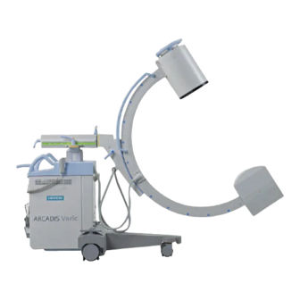
System Description Description of functions System overview The ARCADIS Varic consists of a C-arm system and a monitor trolley. (1) C-arm system with a 23 cm image intensifier and single-focus tube with gen- erator (2) Monitor trolley with keyboard, mouse, USB port, two rotatable TFT displays,... - Page 50 System Description Video splitter live monitor/reference monitor Output for connecting an external live/reference monitor. Implemented as a splitter solution for connection with a 15-pin VGA plug (no galvanic isolation). Audio package Wireless network connection (WLAN) DICOM Standard (Send/Receive, Storage Commitment, Print) DICOM Query/Retrieve (enhancement of DICOM Standard) DICOM Worklist (enhancement of DICOM Standard) DICOM MPPS (enhancement of DICOM Standard)
-
Page 51: C-Arm System
(1) ARCADIS electronics unit (2) Control and display panel (3) Lifting column (4) Horizontal support arm (5) C-arm (6) Handle (7) Image intensifier with integrated TV camera (8) Single tank with X-ray tube unit and integrated collimator ARCADIS Varic SPR2-310.620.30.02.02 of 44... -
Page 52: Control And Display Panel On The C-Arm System
System Description Control and display panel on the C-arm system On the C-arm system you can find the control and display panel with membrane keys and digital displays for performing your examinations. The individual keys and displays are grouped by their functions in different areas. (10) Operating mode selection Selecting image parameters (high-contrast fluoroscopy, image quality,... -
Page 53: Monitor Trolley
DVD R/W drive Wheels with cable deflectors Monitor column optional: height adjustable Storage shelf with USB connection; On/Off switch of ARCADIS Varic optional: Connection for MP3 player including loudspeaker on the rear of the monitor trolley (10) Printer bay (11) Charge state of independent power supply (UPS) (see... -
Page 54: Keyboard At The Monitor Trolley
(5) LED "Interference operation" (lit additionally during battery operation) (6) LED "Error" (lit in case of errors) When the "Error" LED is lit, the ARCADIS Varic is no longer protected against power outages by the UPS. Notify Siemens Service. Operator Manual SPR2-310.620.30.02.02... -
Page 55: Operation
The C-arm system is connected to the monitor trolley with a cable. This cable has plug connectors on both ends and therefore can be replaced directly on site, if necessary. Before starting the ARCADIS Varic, please make sure that the cables are straight (without loops). Do not lay connection cables parallel to other cables. -
Page 56: Connecting The Footswitch
Place the footswitch cable inside the groove for the cable and close the flap. Establishing the equipotential bonding connection The ARCADIS Varic can be connected to a protective ground terminal via the equipotential connector on the C-arm system. This will ensure that the ARCADIS Varic has the same electrical potential as other units connected to the same protective earth terminal. -
Page 57: Arcadis Varic Switching On
System Description ARCADIS Varic Switching on The ARCADIS Varic is operated via a grounded wall socket. The mains cable is on the monitor trolley. Plug the power plug into the appropriate socket. – Power connection is now established. Position the unit so that it is easy to disconnect from the mains. - Page 58 System Description The following functions are set when the ARCADIS Varic is started: Operating mode: The basic setting configured for the body region "All" Register 8: Configuration, Page 5). Iris diaphragm in full format (edges visible). Semi-transparent slot diaphragm in full format.
-
Page 59: C-Arm Movements
Motorized vertical movement of the C-arm. Risk of crushing! In the case of danger, immediately press the EMERGENCY STOP button. Unlock the EMERGENCY STOP by turning it clockwise only after the hazard- ous situation has been resolved. ARCADIS Varic SPR2-310.620.30.02.02 of 44... -
Page 60: Lifting And Lowering The C-Arm
System Description Lifting and lowering the C-arm You can lift and lower the C-arm by motor control using the arrow keys on the control panel of the C-arm system. The lifting column can be lowered to position 1 and further down to position 2. (1) C-arm in position 1 (2) C-arm in position 2 Lifting the C-arm... -
Page 61: Moving The C-Arm Horizontally
You can move the support arm horizontally by up to 20 cm. 20 cm ST OP Release the brake marked in green (arrow). Move the support arm to the desired position while observing the green scale. Lock the brake again. ARCADIS Varic SPR2-310.620.30.02.02 of 44... -
Page 62: Swiveling The C-Arm
System Description Swiveling the C-arm You can move the C-arm horizontally ± 12.5° about the lifting column. 12,5° 12,5° ST OP Release the brake marked in orange (arrow). Swivel the C-arm to the required position. Lock the brake again. Angulating the C-arm You can rotate the C-arm vertically about the horizontal support arm by ±... -
Page 63: Moving The C-Arm Orbitally
Starting from the basic position (0°), you can swivel the C-arm by up to +90° or up to -40° (130° in total). 130° ST OP 130° Release the brake marked in blue (arrow). Swivel the C-arm to the required orbital position while observing the blue scale. Lock the brake again. ARCADIS Varic SPR2-310.620.30.02.02 of 44... -
Page 64: Preparing Exposure
The C-arm can be covered completely or partially with a sterile disposable sheet to protect it against contamination ( Register 11: Options, Page 13). Positioning the C-arm Align the ARCADIS Varic. Release the brakes and set the C-arm to the required position. Page 13) Warning As long as the brakes are not locked after movement, the C-arm system moves freely. -
Page 65: Setting The Semi-Transparent Slot Diaphragm
OPEN and CLOSE simultaneously and holding them approx. 3 sec. This process lasts about 20 sec. During this time the kV and mA indicators will flash. It is not possible to release radiation in this case. ARCADIS Varic SPR2-310.620.30.02.02 of 44... -
Page 66: Setting The Iris Diaphragm
2 places in the fluoro image. The X iris leaves are set such that at least two leaves are visible. When switching on the ARCADIS Varic, the iris diaphragm automatically opens to the full format. -
Page 67: Selecting The Noise Reduction Factor
– The LED lights up when this function is selected. Press this key. – The image is flipped horizontally. – The LED lights up when this function is selected. The image reversal is effective only on the left (live) monitor. ARCADIS Varic SPR2-310.620.30.02.02 of 44... -
Page 68: Positioning An Image For Fluoroscopy
System Description Positioning an image for fluoroscopy To have the image appear on the monitor in the desired orientation during fluo- roscopy, you must rotate it. Object display on the monitor depends upon the C-arm system position relative to the patient. (1) right side of patient (2) left side of patient The rotation angle is displayed on the C-arm system (±... -
Page 69: Selecting The Operating Mode
Every application allows to choose between different optimized programs. The stan- dard setting of the ARCADIS Varic after startup is the basic setting configured for the body region "All", which is typically Continuous fluoroscopy ( Register 8: Configuration, Page 5). - Page 70 System Description Typical clinical procedure: Fracture reposition of the distal upper extremity (e.g. distal forearm fracture) in the plaster room of an emergency outpatient clinic where, under continuous fluoroscopy, the fracture elements are reduced by extension, fixed temporari- ly in the best possible position and then fixed permanently by applying a plas- ter cast, with the additional advantage of dose savings for the patient and medical staff.
- Page 71 By repeatedly pressing an operating mode key that is already activated, you can scroll through the exam sets assigned to the corresponding operating mode. This is only possible if a patient has already been registered. ARCADIS Varic SPR2-310.620.30.02.02 of 44...
- Page 72 – Fluoroscopy mode is selected. – The LED lights up. Upon startup of the ARCADIS Varic, the basic setting configured for the body region "All", which is usually Fluoroscopy, is used as the automatic default Register 8: Configuration, Page 5).
- Page 73 Register 2: Safety, Page 13) If you select a different operating mode or change the exam set, the selection of SIREMATIC curves will change. This depends on the setting of exam sets. ARCADIS Varic SPR2-310.620.30.02.02 of 44...
- Page 74 System Description Subtraction (SUB) The subtraction technique enables an isolated display of the vascular system after injection of the contrast medium by means of background subtraction. Register 5: Examination, Page 21) Press this key. – The Subtraction mode is selected. –...
-
Page 75: Setting The X-Ray Parameters Manually
The mA values assigned to the kV values result from the SIREMATIC curves. Register 9: Technical Data, Page 3) On reaching the end of the curve, the iris diaphragm is opened. The LED flashes. If the iris diaphragm is opened to maximum, an acoustic signal sounds. ARCADIS Varic SPR2-310.620.30.02.02 of 44... -
Page 76: Radiation Release
System Description Radiation release Radiation can be released with the hand switch or the footswitch. Complete image integration as a function of the set k factor (up to max. k = 8, depending on the operating mode) is ensured even for very short exposures ("toe tapping"). -
Page 77: Radiation Release With The Hand Switch
– Radiation is released in the selected operating mode. – The current radiation parameters are displayed on the control panel of the C-arm system. During or at the end of the exposure, an acoustic warning signal sounds (can be configured). ARCADIS Varic SPR2-310.620.30.02.02 of 44... - Page 78 – Holding the key for < 2 seconds: saves the image last recorded (LIH). – Holding the key for > 2 seconds: saves the scene last recorded (LSH). The ARCADIS Varic transfers images from monitor A to monitor B and then stores them in the local database.
-
Page 79: Radiation Release With The Footswitch
The left footswitch is used to activate the currently selected operating mode. Exception: If fluoroscopy (CFC) is selected, the left pedal is assigned the digital radiography (DR) mode. The functionality of the two pedals can be reversed by Siemens Service upon request. Keep the foot pedal pressed during radiation release. -
Page 80: Shutdown
After the 15th switch off using the OFF button, a complete shut down automatically occurs with appropriate notification. If you want to ensure a very short power-up time of your ARCADIS Varic system, we recommend that you initiate a complete shutdown yourself before the maxi- mum number of 15 simple shutdown procedures is reached. -
Page 81: Switching The System Off: Complete Shut Down In The Main Menu
16th switch off using the OFF button), the imaging system is completely shut down before it switches off. When the ARCADIS Varic is switched on again after a complete shutdown, it may take more than 3 minutes, depending on the con- figuration and previous use, for it to reach operational readiness. -
Page 82: Reactivating The System
Reactivating the system If the imaging system cannot be shut down properly after pressing the OFF but- ton and does not react any more, you must deactivate the ARCADIS Varic system as follows: Open the monitor trolley drawer partway and press the Reset button on the bottom of the key panel. -
Page 83: Transport
When transporting the C-arm system and the monitor trolley in the transport position, the floor inclination must not exceed ± 10°. The C-arm system can tip over! Avoid an inclination angle of more than ± 10°. ARCADIS Varic SPR2-310.620.30.02.02 of 44... -
Page 84: Transport And Parking Position Of The C-Arm System
Pull on the plug, not on the cable! The ARCADIS Varic can be switched on again after approx. 5 s. Please note that after finishing an examination, the ARCADIS Varic must be shut down properly before it is disconnected from the power supply. - Page 85 (1) Rolling up the footswitch cable (2) Footswitch holder Roll up the footswitch cable onto the cleat provided and place the footswitch into its holder. When attaching the footswitch, please be careful not to kink the cable. ARCADIS Varic SPR2-310.620.30.02.02 of 44...
- Page 86 System Description Driving the unit (1) Foot brake locked (pedal tilted) (2) Foot brake released (pedal horizontal) Release the foot brake. S T O P S T O P (1) Steering lever shown in the position for forward travel (2) The steering lever can be locked into position for transverse travel to the right or left Lift the steering lever and turn it in the desired direction.
-
Page 87: Monitor Trolley Transport Position
(2) Toggle switch for height-adjustment of the monitors The height of the monitors can be adjusted with the black toggle switch. Press the arrow symbol for Down on the toggle switch. – The monitors automatically move downwards. ARCADIS Varic SPR2-310.620.30.02.02 of 44... -
Page 88: Moving The Monitor Trolley
System Description When the lowest position has been reached, the monitors can be folded. Moving the monitor trolley Release the central brake at the front of the monitor trolley (see arrow) to start moving the trolley. Operator Manual SPR2-310.620.30.02.02 of 44... -
Page 89: Locking The Monitor Trolley
Lock the brake at the front of the monitor trolley. Setting the direction of the monitor trolley In order to set the direction of the monitor trolley, push the center brake upwards with your foot until it stops/engages. ARCADIS Varic SPR2-310.620.30.02.02 of 44... - Page 90 System Description Operator Manual SPR2-310.620.30.02.02 of 44...
- Page 91 Data levels ............................27 Searching for and displaying patient data ................28 Data at the workstation........................28 Opening a data level ......................28 Filtering data ......................... 29 Sorting data .......................... 30 Data on external exchange media....................30 ARCADIS Varic SPR2-310.620.30.02.02 of 60...
- Page 92 Patient data Data in the network ........................31 Printing a data list ........................... 33 Updating and deleting data....................34 Changing patient or examination data..................... 34 Safety notes for changing data ..................... 35 Correcting Data........................36 Rearranging data........................39 History of changes .......................... 40 Changing the work status .......................
-
Page 93: Register 4 Patient Data
This saves time during the examination. HIS/RIS query If your system is connected to a HIS/RIS system (hospital and radiology informa- tion system), you can query and retrieve data for the patient to be examined for preregistration or registration. ARCADIS Varic SPR2-310.620.30.02.02 of 60... -
Page 94: The Patient Registration Window
The Patient Registration window is subdivided into four areas into which you can enter topically coherent data. (1) Personal data of the patient (PATIENT) (2) Hospital-specific data (HOSPITAL) (3) Study-specific data (PROCEDURE) (4) Institution data (INSTITUTION) The input fields can be adapted by Siemens Service. Operator Manual SPR2-310.620.30.02.02 of 60... -
Page 95: Emergency Registration
The patient is registered with provisional data as an emergency patient. As soon data as you have more time after the examination, you must complete the patient and examination data of your emergency patient using the Patient Browser. ARCADIS Varic SPR2-310.620.30.02.02 of 60... -
Page 96: Emergency Registration Window
Patient data Emergency Registration window First finish off or interrupt the current examination. Press the button in the tool bar of the Patient Browser. — or — Call up Patient > Emergency in the main menu. – The Emergency Registration window opens. Click the Exam button in the Emergency Registration window. -
Page 97: Emergency Registration In The Patient Registration Window
Press the key on the symbol keypad. – The Patient Registration window is displayed. Click the Emergency button in the Patient Registration window. – The Patient Registration window is closed. – The Examination task card is opened. ARCADIS Varic SPR2-310.620.30.02.02 of 60... -
Page 98: Registering A New Patient
Patient data Registering a new patient If a patient has never been examined in your hospital or practice before, no data about this patient will be stored on your system. Therefore all the data of this patient must be entered before an examination. Registering If you register a patient and want to examine this patient immediately afterwards, enter all the examination-relevant data into the corresponding input fields. -
Page 99: Entering Data
If you do not know the date of birth you can enter the estimated Age. The system then calculates a date of birth from the current date. In the selection field next to it you can specify whether the age is in years, months or days (for example for infants). ARCADIS Varic SPR2-310.620.30.02.02 of 60... -
Page 100: Hospital-Specific Data
Patient data Hospital-specific data In the HOSPITAL area, you can enter the referring physician, the preliminary diagnosis, and the hospital ward where the patient is located. Enter the hospital-specific data via the keyboard. Select the entries you require from the selection lists. Examination data In the PROCEDURE area, data from the HIS/RIS system (option), if connected, are entered automatically. -
Page 101: Completing Data Entry
Click the Preregister button. – The patient is included in the scheduler. The input fields of the PATIENT area in the Patient Registration window are empty again. You can enter the data of the next patient. ARCADIS Varic SPR2-310.620.30.02.02 of 60... -
Page 102: Registering A Known Patient
HIS/RIS, update the scheduler manually by double-clicking the scheduler icon. This is advisable in particular after switching on or restarting the ARCADIS Varic. Operator Manual SPR2-310.620.30.02.02... -
Page 103: Searching In The Patient Registration Window
– The databases of your system are now searched for the patient with the data entered. – During the search, the Cancel button is displayed instead of the Search button. Thus you can cancel long search processes. ARCADIS Varic SPR2-310.620.30.02.02 of 60... -
Page 104: Accepting Patient Data
Patient data Accepting patient data If only one patient was found at the end of the search, this patient's personal data are automatically transferred to the Patient Registration window. As soon as a second patient was found, your system displays the Patient Search window with the hit list. -
Page 105: Searching In The Patient Browser
Select the study or studies of the patient that you want to perform or repeat. Press the key on the symbol keypad. — or — Select Patient > Register to open the Patient Registration window. ARCADIS Varic SPR2-310.620.30.02.02 of 60... -
Page 106: Completing Your Entries
Patient data Completing your entries After you have transferred the patient data you searched for into the Patient Registration window, check that the data are correct and, if necessary, add any missing data before registering the patient. Click Exam if you want to examine the patient next. –... -
Page 107: Resuming A Commenced Study
All newly generated images are appended to the existing study as a new series. Call up the Patient Browser. Select the relevant study. Call up the Patient Registration window. Click the Exam button. – The Examination task card is displayed and you can resume the study. ARCADIS Varic SPR2-310.620.30.02.02 of 60... -
Page 108: Configuration Of Patient Registration
Patient data Patient data Configuration of Patient Registration You can adapt patient registration flexibly to the individual requirements of your examination practice. You can change the following default settings: The entries in the selection lists of the Patient Registration window. Selection of the databases that you want to be searched when using the search function as well as the search procedure and display of the search re- sults. -
Page 109: Configuring Selection Lists
Possible selection lists You can change and add to the selection lists for the following input fields if these fields are shown in the Patient Registration window: Referring physician Admitting diagnosis Ward Institution name Performing physician Operator ARCADIS Varic SPR2-310.620.30.02.02 of 60... - Page 110 Patient data Creating entries You can create up to 50 entries for each selection list. Under Entering Data, select which selection list you want to edit. Enter new entries in the text input field below and correct or delete the exist- ing entries.
-
Page 111: Configuring Patient Search
In the Searching tab card you can define which databases are to be searched during a patient search, after how many hits the search is terminated, and what information the search list is to contain. ARCADIS Varic SPR2-310.620.30.02.02 of 60... - Page 112 Patient data Specifying databases During a patient search the following databases can be searched: Scheduler database (contains all preregistered patients) Local database (contains all patients who have been examined in the past and whose data have not yet been deleted) Local archive (contains all patients that are stored on the data media currently inserted) Select the databases that you want to search during the patient search.
- Page 113 The network node where the data of the patient displayed in the search list are stored. Enter the column of the search list in which the information is to be entered. Enter the column width (number of characters). Click the information that you want to display. ARCADIS Varic SPR2-310.620.30.02.02 of 60...
-
Page 114: Introduction Patient Browser
Patient data Patient data Introduction Patient Browser The Patient Browser supports you in the administration of the patient and exam- ination data that are stored in the databases of your system. With the Patient Browser you can search for data in a fast and uncomplicated way and then process that data in the browser or in the task cards. -
Page 115: The Patient Browser Window
If you select the lower data levels, you can see which series or procedure steps are stored for a study and which images or action items are stored for a series or procedure step. ARCADIS Varic SPR2-310.620.30.02.02 of 60... -
Page 116: Databases And Drives
Patient data Databases and drives In the Patient Browser you can access patient and examination data that is stored in the various databases of your system or on external data media such as CDs/DVDs. Local Database The local database is the area of your system where patient data and results of current examinations are stored. -
Page 117: Data Levels
In the databases and on the external data media, the patient and examination data are structured hierarchically. This structure helps you find examination results quickly. (1) Database (2) Patient (3) Examination (4) Series (5) Instances The display of the data levels depends on the configuration. ARCADIS Varic SPR2-310.620.30.02.02 of 60... -
Page 118: Searching For And Displaying Patient Data
Patient data Searching for and displaying patient data In the Patient Browser window you can view all the patient and examination data stored in the databases of your system or in the main databases of other network nodes (if connected) and on external archive media. Calling up the You can call up the Patient Browser window either from the main menu or by Patient Browser... -
Page 119: Filtering Data
To open this dialog box, select Options > Configuration. Page 48) Deactivating the filter Call up Filter > Off. Click on the icon button to have all the data displayed again (unfiltered). ARCADIS Varic SPR2-310.620.30.02.02 of 60... -
Page 120: Sorting Data
Patient data Sorting data You can sort the data displayed in the Patient Browser by various criteria. This en- ables you to output the data in a certain sequence and makes it easier to find cer- tain patient and examination data. Select a data level in the navigation area. -
Page 121: Data In The Network
– The Patient Search dialog box is displayed. (1) Input fields for search criteria (search mask) (2) List of search details (3) Display of search results ARCADIS Varic SPR2-310.620.30.02.02 of 60... - Page 122 Patient data Starting a search Enter the known patient data and further search details, if necessary. Unknown data can be replaced by the wildcard *, e.g. T*. In the Node field, specify the network node where you want to search for the data.
-
Page 123: Printing A Data List
Click Print in the Print Preview. – The data list is printed on the default printer. If you wish to print to another printer, select Patient > Print. You can now change the print settings in the dialog box displayed. ARCADIS Varic SPR2-310.620.30.02.02 of 60... -
Page 124: Updating And Deleting Data
Patient data Updating and deleting data Every now and then it is necessary to add or correct patient data or information relating to the study of a patient (e.g. emergency patient). You use the Patient Browser to search for the patient in the database and to edit the corresponding data. -
Page 125: Safety Notes For Changing Data
Wrong diagnosis due to incorrect image information! Correct the attributes which do not correspond, before you rearrange the series/images. Please terminate the active study of the patient before correcting examination data of this patient. ARCADIS Varic SPR2-310.620.30.02.02 of 60... -
Page 126: Correcting Data
Patient data Correcting Data Patient and examination data can be changed and added to in the Correct dialog box. Calling up the dialog Select the patient, study, series or images that you want to correct in the nav- window Correct igation or content area of the Patient Browser. - Page 127 If you do not specify a name, the name with which you logged on to the system is taken as the modifier. Saving changes Click on OK. – The new data are saved and the changes are included in the history of changes. ARCADIS Varic SPR2-310.620.30.02.02 of 60...
- Page 128 Patient data Merging patient data A patient whose name was spelt incorrectly during an examination or who was once registered as an emergency patient is stored in the database twice. As soon as you save the corrected patient name, the dialog box asks you whether you want to merge the examination data of the two patient entries or not.
-
Page 129: Rearranging Data
If you do not specify a name, the name with which you logged on to the system is taken as the modifier. Click on OK. – The changes are saved and included in the history of changes. ARCADIS Varic SPR2-310.620.30.02.02 of 60... -
Page 130: History Of Changes
Patient data History of changes The history of changes is a type of logbook of your local database that is created separately for each data level. Here you can always see what changes and addi- tions have been made to the data of patient and to the information about the patient's examinations. -
Page 131: Changing The Work Status
Read Select Edit > Set State and select the work status you want to assign. Click the appropriate button on the tool bar. – The work status of the selected data objects is changed correspondingly. ARCADIS Varic SPR2-310.620.30.02.02 of 60... -
Page 132: Performance Documentation (Mpps)
Patient data Performance documentation (MPPS) If the DICOM MPPS option is installed, your system creates a performance report during patient registration. During examination and post-processing of the exam- ination results, the report is updated. Before you conclude your work on the examination by archiving, check and add missing entries to the performance report. -
Page 133: Adding Data
Depending on operational requirements, you can transfer the report to the HIS/RIS system. Saving a report Click the Save button. – Your entries are saved to the report and the Modality Performed Procedure Step window is closed. ARCADIS Varic SPR2-310.620.30.02.02 of 60... - Page 134 Patient data Concluding a report Click the Completed button to conclude the report and the examination. – The report and the examination is concluded. A message indicating this is sent to the HIS/RIS system, if connected. You can no longer make changes to the performance report. Exiting a report as discontinued Click the Discontinued button.
-
Page 135: Delete Data
Call up Edit > Delete in the main menu of the Patient Browser. — or — Click on the icon button on the tool bar. – A dialog box is displayed in which you have to confirm again that you really want to delete the selected data. ARCADIS Varic SPR2-310.620.30.02.02 of 60... -
Page 136: Protecting Data From Deletion
Patient data Protecting data from deletion You can protect patient and examination data from accidental deletion. Select the data that you want to protect against deletion in the navigation or content area. Call up Edit > Protect in the main menu of the Patient Browser. —... -
Page 137: Deleting Data In The Scheduler
– The Clear Scheduler dialog box is displayed. Select the entries to be deleted by ticking the relevant check boxes. Confirm your selection with OK to save your settings and delete the corre- sponding procedure steps. ARCADIS Varic SPR2-310.620.30.02.02 of 60... -
Page 138: Patient Browser Configuration
Patient data Patient data Patient Browser Configuration With the Browser Configuration dialog box you can adapt the Patient Browser to your method of working. You can change the following settings: General settings such as the layout of the tool bar and the display of the work status. -
Page 139: General Settings
On the General tab card you can configure the tool bar of the Patient Browser, define which work status is displayed for the examination data, and set the influ- ence of the work status on delete permission. And finally, here you can establish the links to network nodes. ARCADIS Varic SPR2-310.620.30.02.02 of 60... -
Page 140: Configuring The Tool Bar
Patient data Configuring the tool bar You can place buttons for the functions of the Patient Browser that you require frequently on the tool bar and remove rarely used functions. Select an action you want to place on the tool bar as an icon button from the Tool Pool. -
Page 141: Work Status
Patient Browser. Defining delete permission Select the check box of a work status. – Data without this status cannot be deleted without explicit confirmation in a message box. ARCADIS Varic SPR2-310.620.30.02.02 of 60... -
Page 142: Delete Confirmation
Patient data Delete confirmation The default setting is to have your system display a confirmation window before each deletion even if the data concerned have already reached the work status required for deletion. You can activate and deactivate this confirmation in the con- figuration. -
Page 143: Tree View
On the Tree View tab card you can define what information is listed in the con- tent area of the Patient Browser in the hierarchy levels (e.g. patient). You can also hide hierarchy levels in the navigation and content areas and configure the icon display of series and images. ARCADIS Varic SPR2-310.620.30.02.02 of 60... -
Page 144: Selecting A Database And A Data Level
Patient data Selecting a database and a data level Select Database. – The local database view is configured. Select Scheduler. – The display of preregistered patient data is defined in the Patient Browser. Select the data level for which you want to define the entries. The names and information that appear on the Tree View card for the different data levels differ depending on the database that you have called up (e.g. -
Page 145: List Entries
Hiding data levels You can define whether the study, series, or instance hierarchy levels are dis- played in the navigation and content area. Click on the Hide check box to hide this data level. ARCADIS Varic SPR2-310.620.30.02.02 of 60... -
Page 146: Single View
Patient data Single view In the Single View tab card you can define up to which hierarchy level data are to be displayed if the navigation area is hidden. Each data entry is displayed in exactly one line. Operator Manual SPR2-310.620.30.02.02 of 60... -
Page 147: Selecting A Database And A Data Level
With the Display Level radio button you can select the data level that you want to have displayed in the content area when switching from Tree View to Single View. In single view, the content area always shows the same data level. ARCADIS Varic SPR2-310.620.30.02.02 of 60... -
Page 148: List Entries
Patient data List entries You can combine list entries of different information levels by varying the data level for the pool in the Heading Pool from which you then select the required entries. Defining data entries for Heading Pool In the selection list, define the data level from which you want to take list entries for the content area in the Heading Pool. -
Page 149: Configuring Patient Search
Double-click the Patient Search icon. – The Patient Search Configuration window appears. Select or deselect the desired items by clicking or deselecting the correspond- ing check box. Click the OK button. – The settings you have made are saved. ARCADIS Varic SPR2-310.620.30.02.02 of 60... - Page 150 Patient data Operator Manual SPR2-310.620.30.02.02 of 60...
- Page 151 Reviewing and storing a scene..................... 19 Completing the examination ......................20 Special examinations ........................21 Subtraction angiography (SUB) ..................... 21 Roadmap ..........................23 References task card......................25 Layout of the References task card ....................26 Subtask cards ..........................27 ARCADIS Varic SPR2-310.620.30.02.02 of 52...
- Page 152 Examination Displaying reference images ..................... 29 Operation at the monitor trolley...................... 29 Notes ............................ 29 Transferring Images......................30 Holding a reference image....................30 Operation at the C-arm system ...................... 31 Transferring images manually....................31 Using the References task card ................... 32 Native task card .........................
-
Page 153: Safety Information Relating To The Examination Procedure
Surgical intervention in the wrong position! Use lead letters as orientation aids during the exposure. Integrated I.I. laser Depending on the configuration of your ARCADIS Varic, you can use the integrat- aimer ed I.I. laser aimer for positioning the C-arm. -
Page 154: During Examination
Examination Software failure In case of a software failure, restart the ARCADIS Varic by switching it off and then back on using the corresponding keys on the monitor trolley ( Register 3: System Description, Page 34, Register 3: System Description, Page 11). -
Page 155: The Examination Task Card
The task card is displayed on the left monitor, the so-called live monitor: (1) Menu bar (2) Status bar (3) Control area (shown here with maximum functionality in the Extended dis- play mode) (4) Image area ARCADIS Varic SPR2-310.620.30.02.02 of 52... -
Page 156: Menu Bar
The display of the control area and the availability of functions depends on the selected display mode. Depending on the display mode, the following data is displayed within the control area: Information about the current patient Examination settings The current state of the ARCADIS Varic Operator Manual SPR2-310.620.30.02.02 of 52... -
Page 157: Display Modes
This allows for detailed examination settings, with additional information displayed. You can switch between the two display modes at any time with the Basic/Extended button. (1) Control area in the Basic display mode (2) Control area in the Extended display mode ARCADIS Varic SPR2-310.620.30.02.02 of 52... -
Page 158: Patient Data
Examination Patient data The registered patient's last name, first name and date of birth appear in the upper control area. The data are shown in both display modes. Virtual patient anatomy (VPA) The upper control area shows a schematic virtual patient anatomy for selecting a body region (VPA = Virtual Patient Anatomy). -
Page 159: Radiation Data (Extended Display Mode Only)
The reason for this convention is that in typical applications the object to be ex- amined is located approximately 30 cm in front of the I.I. Depending on country-specific regulations, you can have Siemens Service change the display so that it indicates the air kerma and cumulated air kerma value instead of the area dose product. -
Page 160: Image Area
Examination Image area In the image area the fluoroscopic images are displayed during and after expo- sure. Additional information may be shown as image text, depending on the con- figuration (see Register 6: Image Processing, Page 78). (1) Information on kV and mA (2) Window value and LUT information Live images As soon as the exposure (i.e. -
Page 161: Performing The Examination
In the Examination card standard exposure parameters for the medical applica- tion area Ortho/Trauma are already preset. If these settings are appropriate for your examination, you can start the exposure immediately on the ARCADIS Varic Page 17). To examine other body regions, you must first select them in the Examination task card. -
Page 162: Basic Display Mode
Examination Basic display mode In the simple display mode, the user only has to select the body region. The med- ical application area, the examination program and the operating mode are then preset automatically. You can define the presettings for individual body regions in the Basic setting configuration window ( Register 8: Configuration, Page 5). -
Page 163: Extended Display Mode
Each medical application area is assigned a specific standard program. As soon as the application area is activated, you can perform an X-ray examination right away. Selecting the application area Select the required medical application area for your examination in the list. ARCADIS Varic SPR2-310.620.30.02.02 of 52... -
Page 164: Body Region
Examination Body region If you want to X-ray a specific body region within an application area, several examination programs adapted especially to this special body region are at your disposal. They can be selected using the VPA (Virtual Patient Anatomy). Selecting a body region Click on the body region that you want to examine. -
Page 165: Exam Set
If you change the exam set, the fluoroscopy mode is automatically set. Even if a different LUT is stored with the new exam set, the display of the current image (LIH) or of the subtracted image does not change (the current LUT is main- tained). ARCADIS Varic SPR2-310.620.30.02.02 of 52... -
Page 166: Operating Mode
Examination Operating mode The different operating modes are defined in each examination set. They can be activated at the monitor trolley and at the C-arm system as well as with the multifunctional footswitch (option). The default setting is Fluoroscopy: Switching the operating mode Use the selection list to select another operating mode, if necessary. -
Page 167: Acquisition
– The saved image is displayed on the right (reference) monitor ( Page 25). If the examination program used is configured to save all images automatically, the Save Image key is inactive. ARCADIS Varic SPR2-310.620.30.02.02 of 52... - Page 168 Examination Storing images (after radiation) Press this key on the control panel of the C-arm system. – or – Press this key on the hand switch. – Holding the key for < 2 seconds: saves the image last recorded (LIH). –...
-
Page 169: Reviewing And Storing A Scene
– You can load the scene into the Viewing task card at any time and review it there. If the exam set used is configured to automatically save all images, manual saving is not necessary and therefore not possible. ARCADIS Varic SPR2-310.620.30.02.02 of 52... -
Page 170: Completing The Examination
Examination Completing the examination After you have completed your exposures, the last acquired image is displayed on the left monitor. Now you finish the examination of the current patient. If you want to examine the next patient immediately afterwards, you can register him or her at once. -
Page 171: Special Examinations
Register 8: Configuration, Page 18) Landmark In some cases it is useful to see the anatomy surrounding the contrast-filled blood vessels. This can be configured gradually prior to the examination using the Landmark function. Register 8: Configuration, Page 18) ARCADIS Varic SPR2-310.620.30.02.02 of 52... - Page 172 Examination Performing Prerequisite: The patient to be examined has been registered. subtraction Make the necessary settings for the examination. angiography Page 11) Set the Subtraction mode in the Examination task card or by pressing the corresponding key on the control panel. –...
-
Page 173: Roadmap
Inject the contrast medium as soon as the syringe symbol appears on the screen. Keep the radiation release button pressed until the vessel is filled with contrast medium. Let go of the radiation release button. – Radiation is stopped. ARCADIS Varic SPR2-310.620.30.02.02 of 52... - Page 174 Examination Using the fill image Prerequisites: from subtraction A subtraction angiography (SUB operating mode) was performed at any time dur- angiography ing the current examination. The symbol for an existing subtraction mask is shown in the control area. Press the RoadMap key on the control panel once. –...
-
Page 175: References Task Card
The References task card is used to display specific images during an examina- tion. Reference images may be: preoperative images, incl. images of other modalities (e.g. CT, MR) images of current examinations images from previous examinations ARCADIS Varic SPR2-310.620.30.02.02 of 52... -
Page 176: Layout Of The References Task Card
Examination Layout of the References task card (1) Menu bar (2) Image area (3) Control area with subtask cards Operator Manual SPR2-310.620.30.02.02 of 52... -
Page 177: Subtask Cards
Using the View, Image and Tools subtask cards, you can easily change the dis- play of reference images and perform measurements, if necessary. The Tools subtask card is available if your ARCADIS Varic includes the "Measure angles and distances" option. - Page 178 Examination View subtask card The View subtask card contains buttons for setting the layout. Division of the screen (Single view, 4:1, 9:1 and 16:1) Image stripe display (stripe) Image stack display (stack) Image subtask card On the Image subtask card you will find tools for image processing. Reduce image size to half (factor 0.5) Zoom in to double image size (factor 2.0)
-
Page 179: Displaying Reference Images
Once a patient has been registered for an examination, only images of the regis- tered patient can be transferred to the References task card. ARCADIS Varic SPR2-310.620.30.02.02 of 52... -
Page 180: Transferring Images
Examination Transferring Images Selecting images Load the images of the requested patient into the Viewing task card by using the Patient Browser. Select the reference images in the image area. You can also select a single frame from a series as reference image (with Subtraction option). -
Page 181: Operation At The C-Arm System
– If you continue with the examination, the last stored image is always dis- played on the right monitor. If Hold Reference is activated for a particular image, this image is permanently available on the right monitor. Page 30) ARCADIS Varic SPR2-310.620.30.02.02 of 52... -
Page 182: Using The References Task Card
Examination Using the References task card Besides transferring images, you can select other important functions of the References task card from the C-arm system. Scrolling Scrolling to the next reference image. Scrolling to the previous reference image. Changing the image display Toggling between single frame and multiple frame display. -
Page 183: Native Task Card
Examination Native task card The Native task card is available if your ARCADIS Varic provides the Subtraction operating mode (option). The Native task card allows you to have subtraction images shown on the left monitor and simultaneously displayed as native (unsubtracted) images on the right monitor. -
Page 184: Displaying Native Images
Examination Displaying native images There are basically two cases in which you use the Native card for displaying unsubtracted images: During an examination simultaneously with the display of currently calculated subtraction images in the Examination card Outside of examinations, simultaneously with the display of subtraction imag- es from the local database in the Viewing card Native images during examinations If you are working in the Subtraction mode and want to have the subtracted... -
Page 185: Native Images From The Database
Now you can load images of the next patient. Select Patient > Close Patient in the main menu of the Viewing task card. – The images in the Viewing and Native task cards are unloaded. Both task cards are empty now. ARCADIS Varic SPR2-310.620.30.02.02 of 52... -
Page 186: Reports
Examination Reports Certain examination data can be stored as structured reports (SR). ARCADIS Varic offers the following types of reports: Radiation Summary Report LithoReport The reports serve to document examination and treatment data. They are mostly generated automatically. You can read, edit and print the reports and export sta- tistics. -
Page 187: Radiation Summary Report
(2) Generation status EXAMINATION REPORT: Treatment in process, report is being generated. POSTPROCESSING REPORT: Treatment is finished, the report has been completed and stored and can be postprocessed. (3) Work status and verification status (4) Content area ARCADIS Varic SPR2-310.620.30.02.02 of 52... -
Page 188: Opening A Report
Examination Opening a report For the current patient Select Reporting > Open Report in the Viewing task card. – The report for the current patient is opened. If several reports exist for the patient loaded in the Viewing task card, a dialog box is displayed in which you select the required report. -
Page 189: Printing A Report
— or — Click this button in the report window or in the print preview. – The Print Report dialog box is opened. Here you can make the necessary print settings and start the print job. ARCADIS Varic SPR2-310.620.30.02.02 of 52... -
Page 190: Lithoreport
LithoReport The LithoReport is generated for extracorporeal shockwave lithotripsy (ESWL) provided that the lithotripsy function is enabled on your ARCADIS Varic system and the lithotripter is connected to the C-arm system. Part of the data are automatically recorded during treatment. Any other data can be added and postprocessed by you at any time. -
Page 191: Opening A Report
On the Patient/Diagnosis card, you enter data relating to the diagnosis and your diagnostic data organization. Click the Patient/Diagnosis card into the foreground. – The patient data are automatically transferred from the registration. Enter the missing data in the active fields. Click Apply. ARCADIS Varic SPR2-310.620.30.02.02 of 52... - Page 192 Examination Entering treatment On the Therapy card, you enter data in preparation for treatment. data Click the Therapy card into the foreground. – The shockwave data of the treatment are entered automatically. Enter the missing data in the active fields. Click Apply.
-
Page 193: Printing A Report
— or — Click this button in the report window or in the print preview. – The Print Report dialog box is opened. Here you can make the necessary print settings and start the print job. ARCADIS Varic SPR2-310.620.30.02.02 of 52... -
Page 194: Export For Statistical Evaluations
Examination Export for statistical evaluations In the Viewing task card you can have statistical data on a LithoReport compiled taking into account other LithoReports, and export the data in meta format. The exported file can be opened and edited with different programs, e.g. - Page 195 – The data search is started and the file is exported. A progress bar informs you of the progress of the export process. Click on Close. – The dialog box closes. The export process is continued in the background until it is successfully completed. ARCADIS Varic SPR2-310.620.30.02.02 of 52...
-
Page 196: Configuration
Examination Configuration The generation, printing and exporting of reports is configured in the Structured Reporting dialog. Depending on the type of report (LithoReport or Radiation Summary Report), you have different configuration possibilities. Calling up the configuration window You can call up the configuration window from the syngo Configuration Panel. Select Options >... -
Page 197: Configuring Selection Lists
Moves the active list entry up one line. Moves the active list entry down one line. If necessary, select the list entry that you want to edit and click on the icon of the required function. ARCADIS Varic SPR2-310.620.30.02.02 of 52... -
Page 198: Defining Designations For Stone Locations
Examination Defining designations for stone locations On the Stone locations card, typical body positions for nephroliths are displayed. Every position is marked by a small square. You can give a name to each of these locations. Click the Stone locations card into the foreground. Click on the square of the position to be named. -
Page 199: Defining Print Settings
Select the required printer from the Default printer selection list. Select the required paper size from the Default papersize selection list. The default print settings on the General subcard are valid for the LithoReport and the Radiation Summary Report. ARCADIS Varic SPR2-310.620.30.02.02 of 52... - Page 200 Examination Displaying the On the Litho subcard, you can define when a report is to be shown automatically. LithoReport Click the Litho subcard into the foreground. automatically Check the check box after creation, if you want the report to be displayed automatically after it has been generated.
-
Page 201: Configuring The Radiation Summary Report
Click the Rad. Sum. subcard into the foreground. Summary Report automatically Check the check box Print after end examination, if you want to print the Radiation Summary Report automatically at the end of the examination. ARCADIS Varic SPR2-310.620.30.02.02 of 52... -
Page 202: Applying Configuration Settings
Examination Applying configuration settings After you have made all the required settings, you apply them to your system. Click OK to apply the settings and to close the configuration window. Click Apply to apply the settings without closing the configuration window. Operator Manual SPR2-310.620.30.02.02 of 52... - Page 203 Windowing with the keyboard....................36 Restoring window values ..................... 36 Edge enhancement ......................37 Zooming and panning images ......................38 Zooming images ........................38 Panning images ........................41 Enlarging an image section....................42 Inverting images ..........................43 ARCADIS Varic SPR2-310.620.30.02.02 of 78...
- Page 204 Image Processing Rotating images ..........................44 Flipping images..........................45 2D Evaluation (option)......................47 Calibration ............................47 Measuring distances and angles ....................49 Drawing a distance line, measuring the distance ..............49 Measuring an angle ......................50 Hiding/deleting graphic elements ..................52 Setting a shutter ..........................
-
Page 205: Introduction
(e.g. MR/CT). Storing, filming and You can save the images you have processed and evaluated, you can print them transferring images or expose them on film or send them to other locations in your hospital. ARCADIS Varic SPR2-310.620.30.02.02 of 78... -
Page 206: The Viewing Task Card
Image Processing The Viewing task card As soon as you have loaded images into the Viewing task card, the task card moves into the foreground. You can, however, switch to other applications at any time and resume image processing on the Viewing task card later. The Viewing task card is divided into four areas. -
Page 207: Image Area
The Extended display mode contains additional functions for detailed evaluations and post-processing. You can switch between the two display modes at any time with the Basic/Extended button. ARCADIS Varic SPR2-310.620.30.02.02 of 78... -
Page 208: Patient Information
Image Processing (1) Control area in the Basic display mode (2) Control area in the Extended display mode Patient information In the upper part of the control area, you can see the names of the patients whose images are currently loaded in the Viewing task card. In the Viewing task card, you can manage up to three patients. -
Page 209: Subtask Cards
Division of the screen (full screen 1:1, 4:1, 9:1 and 16:1) Image stripe display (stripe) Image stack display (stack) Showing/hiding image text Showing/hiding graphic elements and comments ARCADIS Varic SPR2-310.620.30.02.02 of 78... - Page 210 Image Processing Tools subtask card The Tools subtask card includes keys for image evaluation and commenting (the Basic display mode only has the first row of keys). Use a shutter Magnifier Insert an annotation into the image Angle (option) Distance (option) Distance calibration (option) Operator Manual SPR2-310.620.30.02.02...
- Page 211 Switch brightness/contrast characteristic (LUT) to previous (–) and next (+) Reduce (–) and increase (+) edge enhancement Inverting gray-scale values Reduce an image by factor 0.5 Enlarge an image by factor 2.0 Zoom or pan the image Rotating an image ARCADIS Varic SPR2-310.620.30.02.02 of 78...
- Page 212 Image Processing Sub subtask card The Sub subtask card is only available with the Subtraction option. (optional) Pixelshift Auto Pixelshift Change the mask – and + Dual Channel Mode (Sub/Native Display) Subtracted image on monitor A (left) Native image on monitor B (right) Display the anatomical background Operator Manual SPR2-310.620.30.02.02...
- Page 213 Image Processing Movie subtask card The Movie subtask card contains control functions to play a scene as a movie. Start (review speed matches the storage rate). Review at half/double speed. Pause/stop. Previous/next frame. Show previous/next scene. ARCADIS Varic SPR2-310.620.30.02.02 of 78...
- Page 214 Image Processing Other control The keys in the lower segment of the control area have the following functions: functions Copy an image into the References task card Reset all Copy to film sheet Operator Manual SPR2-310.620.30.02.02 of 78...
-
Page 215: Loading And Displaying Images
Viewing task card later. Click the Viewing tab on the left-hand edge of the screen. – The Viewing task card is placed in the foreground. Select the desired display mode with the Basic/Extended button. ARCADIS Varic SPR2-310.620.30.02.02 of 78... -
Page 216: Transferring Images From The Patient Browser
Image Processing Transferring images from the Patient Browser You can search for image data that you have stored in the local database or in the archive using the Patient Browser and then load the data into the Viewing task card. Select Patient >... -
Page 217: Displaying Images And Series
Click the Series Stack button on the View subtask card. – All images of a series are now arranged in a stack one on top of the other. You can see the first image of each series. ARCADIS Varic SPR2-310.620.30.02.02 of 78... -
Page 218: Subdividing The Image Area
Image Processing Subdividing the image area With the division of the image area, you define the number and size of the seg- ments in the image area. Switch to a large format display with just a few images on the screen if you want to see diagnostic details. -
Page 219: Showing And Hiding Image Text
You can then decide whether you want to have the image text shown in the image or not. Select View > Hide Text. Click the Hide Text button on the View subtask card. ARCADIS Varic SPR2-310.620.30.02.02 of 78... -
Page 220: Displaying And Hiding Graphic Elements
Image Processing Displaying and hiding graphic elements Like text information, you can have graphics (e.g. distance lines) and annotations displayed or hidden. Click the Hide Graphics button in the View subtask card. Select View > Hide Graphics in the menu bar. –... -
Page 221: Scrolling And Selecting Images
The image text displayed will help you identify the relevant image stacks. This applies in particular if stacks with black segments have been moved; in this case scroll back to the images first. ARCADIS Varic SPR2-310.620.30.02.02 of 78... -
Page 222: Scrolling Image By Image
Image Processing Scrolling image by image Within a study, you can scroll through the loaded images and series image by image. Scrolling with image Select Scroll > Next Image or Scroll > Previous Image. stripe display Scroll with the Image- or Image+ keys of the symbol keypad. –... -
Page 223: Scrolling Page By Page
Press the Home key. – You jump to the first page of the study. The image area is filled with images. The first image of the series is displayed in the top left-hand corner of the image area. ARCADIS Varic SPR2-310.620.30.02.02 of 78... - Page 224 Image Processing Scrolling with the The third way of scrolling through the images and series of a study is to use the scroll bar scroll bar. (1) Scroll arrow for first page (2) Scroll symbol for previous page (3) Scroll arrow for previous page (4) Slider (5) Scroll arrow for next page (6) Scroll symbol for next page...
- Page 225 Drag the slider up or down with the mouse until the page you require is dis- played. (The page number is also displayed.) If you click the scroll bar above or below the slider, you scroll backward or forward by one page. ARCADIS Varic SPR2-310.620.30.02.02 of 78...
-
Page 226: Scrolling From Series To Series
Image Processing Scrolling from series to series You cannot only scroll image by image or page by page, but also by entire series if you have loaded more than one series of a study into the Viewing task card. It depends on the selected display which images are subsequently displayed in the image area. -
Page 227: Selecting Images
Default input focus When you load images onto the Viewing task card, the input focus is in the default position in the top left segment of the image area. ARCADIS Varic SPR2-310.620.30.02.02 of 78... - Page 228 Image Processing Placing the input focus Using the left mouse button, click into the segment of the image area on with the mouse which you want to place the input focus. An explicitly selected image or an explicitly selected graphic is deselected if you place the input focus on a segment, even if you only click on the same segment.
-
Page 229: Selecting Images Explicitly
Call up Edit > Select On Succeeding in the main menu. – The selected image and all the following images are now selected. If you have explicitly selected images of different series, the remaining images of these series are selected starting with those images. ARCADIS Varic SPR2-310.620.30.02.02 of 78... - Page 230 Image Processing Selecting a complete First select an image of the required series explicitly by clicking on it holding series explicitly the Ctrl key down or place the input focus on the image by clicking on it. Call up Edit > Select Series in the main menu. –...
-
Page 231: Selecting Direct Image Processing
Place the mouse cursor on an image which is not selected and edit the image, for example, by windowing. – The input focus is placed on this image. If graphics were previously explicitly selected in the input focus, they remain explicitly selected. ARCADIS Varic SPR2-310.620.30.02.02 of 78... -
Page 232: Viewing Images In Movie Mode
After an examination, you can start movie mode to check the quality of the scenes you just acquired. Movie mode is possible only for scenes generated with the ARCADIS Varic. You cannot view imported series in film mode. This also applies to scenes in the "JPG lossless"... - Page 233 Select Scroll > Movie at double frame rate or click the button. – The movie is started with double the frame rate. The playback speed may be reduced by postprocessing activities, edge enhance- ment or subtraction. ARCADIS Varic SPR2-310.620.30.02.02 of 78...
- Page 234 Image Processing Stopping the movie Select Scroll > Pause movie or click the button. – The running movie is stopped. – If you continue playback of the movie, it will start from the segment where you paused. Stopping movie mode Click the Stop button.
-
Page 235: Editing Images
You can also rotate, flip or invert images for certain diagnostic problems. Extreme window values can impair image quality. With scenes, the image processing functions are applied to all images of a series. ARCADIS Varic SPR2-310.620.30.02.02 of 78... -
Page 236: Windowing Images
Image Processing Windowing images Imaging methods provide information in the form of gray scale images with up to several thousand different gray scale values. Windowing means to emphasize the range of gray scales of the relevant area and tissue type. The first step in windowing therefore consists in determining the window center, i.e. -
Page 237: Windowing Using The Mouse
– As soon as you release the mouse button, the new window values are also applied to all the other selected images or the selected scope of action. The changed window values are displayed immediately in the image (interactive windowing). ARCADIS Varic SPR2-310.620.30.02.02 of 78... -
Page 238: Windowing With The Keyboard
Image Processing Windowing with the keyboard For fine adjustment of the window values, you can also use the keys on the sym- bol keypad of the keyboard. Pay attention to the current scope. Setting the contrast Press the Width- or Width+ button. –... -
Page 239: Edge Enhancement
The higher the filter setting, the more structures are enhanced and the less they are smoothed. Click the Edge Filter Previous button on the Image subtask card. Select Image > Edge Filter Previous. – The image is displayed with less enhanced structures. ARCADIS Varic SPR2-310.620.30.02.02 of 78... -
Page 240: Zooming And Panning Images
Image Processing Zooming and panning images You can zoom in on sections of images that you are particularly interested in (zooming). If the enlarged image then no longer fits in the segment, you can pan it until the relevant area is in the center of the segment again. Zooming images The Viewing task card provides you with several possibilities of enlarging or reducing images. - Page 241 Image Processing Click the Zoom Out By 0.5 button. – The zoom factor of an image is halved. Click the Zoom In By 2.0 button. – The zoom factor of an image is doubled. ARCADIS Varic SPR2-310.620.30.02.02 of 78...
- Page 242 Image Processing Zooming with the The left mouse key is used to select or deselect images and objects. However, mouse you can also switch over the function of the left mouse button to perform zoom- ing and panning. Select Image > Zoom/Pan. Click the Zoom/Pan button on the Image subtask card.
-
Page 243: Panning Images
Otherwise, you would pan the graphic element and not the content of the image. Restoring image Select Image > Reset Zoom & Pan. display – The original size with which the images were last stored in the database is restored. ARCADIS Varic SPR2-310.620.30.02.02 of 78... -
Page 244: Enlarging An Image Section
Image Processing Enlarging an image section Instead of zooming an image and then panning it so that the relevant section is in the center of the screen again, you can also quickly select specific image sections and display them in a segment in maximum size. Select the image in which you want to display an enlarged image section. -
Page 245: Inverting Images
Select the images that you want to edit. Select Image > Invert Gray Scale. — or — Click the Invert Gray Scale button on the Image subtask card. To reset the original view, select Image > Invert Gray Scale again. ARCADIS Varic SPR2-310.620.30.02.02 of 78... -
Page 246: Rotating Images
Image Processing Rotating images Click on the image that you want to edit. Select Image > Rotate. — or — Click the Rotate button on the Image subtask card. – The shape of the mouse cursor indicates that you can rotate the image freely to the left or to the right. -
Page 247: Flipping Images
The Flip function allows you to easily compare images of series that were ac- quired in a different patient position or direction of examination. Flipping images Select the images that you want to edit. vertically Select Image > Flip Vertically. ARCADIS Varic SPR2-310.620.30.02.02 of 78... - Page 248 Image Processing Flipping images Select the images that you want to edit. horizontally Select Image > Flip Horizontally. Operator Manual SPR2-310.620.30.02.02 of 78...
-
Page 249: Evaluation (Option)
(typically in the center of the measur- ing field to avoid I.I. distortions). Select the required image. Call up Tools > Calibration. — or — Click the Calibration button of the Tools subtask card. ARCADIS Varic SPR2-310.620.30.02.02 of 78... - Page 250 Image Processing Drawing a distance Move the mouse cursor into the image. line – The cursor changes shape. Click on the image to set the starting point and drag a line to the vertex by using the mouse. – As soon as you move the mouse, the line is displayed. Release the mouse button to finish the line.
-
Page 251: Measuring Distances And Angles
– The cursor changes shape. Place the mouse cursor on the starting point of the distance line. Hold the left mouse button down and drag out a line. Release the mouse button to finish the line. ARCADIS Varic SPR2-310.620.30.02.02 of 78... -
Page 252: Measuring An Angle
Image Processing Measuring an angle You can define an angle by two lines, the legs of the angle, that you draw on the image. The system then calculates the angle between the two lines drawn in clockwise. If the angle is larger than 180°, the program subtracts 180°. Drawing an angle Call up Tools >... - Page 253 If the angle approximates to 90°, 180°, 270°, it is not clear whether the angle between the legs or the supplementary angle has been drawn. Therefore, annotate the angle when you display the supplementary angle. ARCADIS Varic SPR2-310.620.30.02.02 of 78...
-
Page 254: Hiding/Deleting Graphic Elements
Image Processing Hiding/deleting graphic elements You temporarily hide the graphic elements (distance lines, angles and text) or per- manently remove them from the image. Hiding Select View > Hide Graphics from the menu. – All drawn graphic elements are hidden. –... -
Page 255: Setting A Shutter
Hold the left mouse button pressed and drag out a rectangle for the shutter. By clicking on the border of the image you can select a shutter which you can then move or resize. Release the mouse button. – The area outside the shutter is displayed black. ARCADIS Varic SPR2-310.620.30.02.02 of 78... - Page 256 Image Processing You can transfer images in the current shutter setting to the Filming task card for printing (menu Patient > Copy to Film Sheet). If the image contains addition- al graphic elements, they may not be hidden (menu View > Hide Graphics). Otherwise, the shutter cannot be transferred to the film sheet, and printing is impossible.
-
Page 257: Text In Images
# @ ' " \ { ( Confirm your text entry with the Return key. — or — Click into the image outside the text. – The text is displayed white with shading. ARCADIS Varic SPR2-310.620.30.02.02 of 78... - Page 258 Image Processing Using predefined text Frequently used texts can simply be selected from a list once they have been configured. Page 73) Call up Tools > Annotation Arrow. Using the right mouse button, click on the position in the image where you want to insert the text.
-
Page 259: Subtraction Processing
Click this button in the Sub subtask card. – In the Viewing task card the subtraction images are displayed on the left monitor. – In the Native task card the corresponding native images are displayed on the right monitor. ARCADIS Varic SPR2-310.620.30.02.02 of 78... -
Page 260: Selecting Another Mask
Image Processing Selecting another mask You can select an image without contrast medium (mask), that you want to sub- tract from a stack of images acquired with contrast medium. To do this, scroll simultaneously through the stacks of subtraction images. Selecting the Select Sub >... -
Page 261: Achieving Exact Covering Of Image And Mask
To shift the mask in big steps, move the mouse pointer at the edge of the image. For fine mask shifting, move the mouse pointer in the center of the image. Click this button again. – The pixelshift function is switched off. The button is displayed deselected. ARCADIS Varic SPR2-310.620.30.02.02 of 78... - Page 262 Image Processing Automatic pixelshift Click this button. – The button is displayed selected. – The mouse cursor changes into a rectangle. Move the rectangle to the position in the image where misalignment is most evident. Click this position in the image. –...
-
Page 263: Saving, Transferring, Documenting, Closing Images
Note that the newly saved data may not immediately be shown in the Patient Browser. The display should first be updated manually, in particular after com- prehensive storage processes (select View > Refresh in the Patient Browser). ARCADIS Varic SPR2-310.620.30.02.02 of 78... - Page 264 Image Processing Calling up the Save As Only images of the same study can be saved together in one series. dialog box First select the images or series that you want to save. Select Patient > Save As. – The Save As dialog box is displayed. Saving images as a You can save all selected images in a new series.
-
Page 265: Restoring Image Display
Select the images in the image area of the Viewing task card. Select Edit > Reset all. – or – Click this button. – All selected images are reset to their original state (before they were pro- cessed). ARCADIS Varic SPR2-310.620.30.02.02 of 78... -
Page 266: Archiving, Sending Or Filming Images
Image Processing Archiving, sending or filming images After an examination or postprocessing, the images are stored in the local data- base from where they can be accessed for reporting or documentation, for exam- ple. Archiving images Using the Archive to... function, you can save patient and examination data to an archive via the network (only DICOM option). -
Page 267: Sending Images (Dicom Option)
Sending images to a Select Transfer > Send to..specific network Select the required network address(es) in the Send To dialog box. address Click Send. – The selected data are sent to the required address(es). ARCADIS Varic SPR2-310.620.30.02.02 of 78... -
Page 268: Filming Images
Image Processing Filming Images You can also use the Viewing task card to select images and copy them to Filming (DICOM option). Make sure the printer is switched on before you send images to print. Transferring images to Select the images in the image area of the Viewing task card. Filming Select Patient >... -
Page 269: Transferring Images To The References Task Card
Select the images or series you want to process in the Viewing task card. Select Patient > Copy to Reference Monitor. – or – Click this button. – The images are copied to the References task card. Register 5: Examination, Page 29) ARCADIS Varic SPR2-310.620.30.02.02 of 78... -
Page 270: Closing The Patient
Image Processing Closing the patient When you have finished image processing and evaluation in the Viewing task card, you can close the patient. If images of several patients are loaded, you can close all patients in one step. If images of a current examination are loaded, the patient will be closed when the examination is ended. -
Page 271: Viewing Configuration
Select Options > Configuration in the main menu. Double-click the Viewing button. – The Viewer Configuration window appears. — or — Double-click the Image Text Editor button to configure the image text dis- play. – The Image Text Configuration window is displayed. ARCADIS Varic SPR2-310.620.30.02.02 of 78... -
Page 272: Concluding Configuration
Image Processing Concluding configuration If you have changed the settings in the cards of the configuration window, you must confirm them. If you have changed parameters by accident, you can reset these values to default values or reject all your changes. Applying changes Confirm with OK. -
Page 273: Division Of The Image Area
Click the Layout card into the foreground. Select the size of the layout from the selection list. – After the images have been loaded into the Viewing task card, they are displayed in the selected layout size. ARCADIS Varic SPR2-310.620.30.02.02 of 78... - Page 274 Image Processing Setting the type of Click the Stripe option. layout – You can view the loaded series of a study one after the other image by image. Click the Stack option. – All images of a series are now arranged in a stack one on top of the other. Click the Unchanged option.
-
Page 275: Creating Annotation Texts
Click on the Paste button. Double-click the empty box. Enter the new text. Click on the Paste button or press the Enter-key. – The new annotation text is placed in the top position of the list. ARCADIS Varic SPR2-310.620.30.02.02 of 78... - Page 276 Image Processing Changing text Double-click an existing box. Enter the new text. Click on the Enter key. – The modified annotation text is displayed. Deleting an existing Select a text in the list of annotation texts. text Click on the Delete button. –...
-
Page 277: Exporting Sub/Roadmap Image Data
Subtraction functions can no longer be performed with these data. – export for Native Image Display Native images are saved. These can also be viewed in non-Siemens sys- tems. – export as ’Raw Data’ The original data set is saved. It can be post-processed in other ARCADIS systems or in systems with subtraction functions. -
Page 278: Layout In The References Task Card
Image Processing Layout in the References task card The Ref. Split card lets you determine how to split the image area in the References task card when the Monitor split button at the C-arm system is pressed. Click the Ref. Split card into the foreground. Select the size of the layout from the selection list. -
Page 279: Loading Reference Images During An Examination
– Automatically saved individual images are always loaded in the References task card. Click the Multi Frame Images check box. – Automatically saved multiframe images (scenes) are always loaded in the References task card. In the default setting, both check boxes are activated. ARCADIS Varic SPR2-310.620.30.02.02 of 78... -
Page 280: Configuring Image Text Display
Image Processing Configuring image text display In the Image Text Configuration dialog you can set which image text informa- tion is to be displayed by default with individual basic formats. The dialog box is opened by clicking the Image Text Editor button in the syngo Configuration Panel. - Page 281 Changing the layout of the film sheet..................... 35 Image, text and graphic display ...................... 37 Checking the data transfer ....................43 Viewing and manipulating film jobs ....................44 Calling up the Film Task Status dialog .................. 44 Manipulating film jobs ......................46 ARCADIS Varic SPR2-310.620.30.02.02 of 98...
- Page 282 Documentation Configuration for filming/printing ..................51 Calling up the configuration window....................51 Configuring film layouts ........................52 Selecting a layout ......................... 52 Configuring film job settings....................54 Configuring film sheets......................56 Linking layouts to a study or series....................58 Assigning film layouts......................59 Canceling a film layout assignment ..................
- Page 283 Setting data compression for storing ................... 94 Defining the work status for storing ..................95 Network Nodes (option)........................96 Setting data compression for sending .................. 97 Setting retries ........................97 Defining the work status for sending ................... 98 ARCADIS Varic SPR2-310.620.30.02.02 of 98...
- Page 284 Documentation Operator Manual SPR2-310.620.30.02.02 of 98...
-
Page 285: Introduction For Filming/Printing
Please remember that not all transfer options may be available on your system. The devices and network nodes available depend on the individual configuration of your system and the options installed. ARCADIS Varic SPR2-310.620.30.02.02 of 98... -
Page 286: Filming And Printing
Documentation Filming and printing Image material is filmed/printed in two steps: First, specify on one of the task cards or in the Patient Browser which images or series you want to print or expose on film. Then transfer the selected im- ages to the virtual film sheet. - Page 287 Instead, the images to be printed will first be collected in the virtual film sheet. They can be edited after the examination and manually sent to the printer. ARCADIS Varic SPR2-310.620.30.02.02 of 98...
-
Page 288: Layouts And Settings
Standard layout Provided that you do not make any changes to the default film settings, you always work with the general default layout defined by Siemens Service during installation of your system. Changing film settings If you are not satisfied with the default film settings (default layout), you can change individual film settings using the virtual film sheet. -
Page 289: The Filming Task Card
The Filming task card is divided in four main areas. (1) Menu bar with menu entries for filming (2) Control area allowing easy access to processing functions (3) Display of the film sheets (virtual film sheet) (4) Status bar for system messages ARCADIS Varic SPR2-310.620.30.02.02 of 98... -
Page 290: The Film Preview Window
Documentation The Film Preview window If you want to obtain a quick overview of the film jobs in the queue that have not yet been sent to the camera or printer, you can use the Film Preview window. (1) Maximize to Filming task card (2) Film jobs (3) Display of film sheets (4) Spin box for selecting the number of copies... -
Page 291: Automatic/Manual Filming
Siemens Service or your system administrator has configured one or several cameras printers/cameras for your ARCADIS Varic system. At the same time, the names of output devices that you can choose from selection lists as well as the specified paper/film size were set up. -
Page 292: At The Monitor Trolley
Documentation At the monitor trolley You have the possibility of selecting and filming/printing single images or all images of a series, a study or a patient. Selecting images You decide on the Viewing task card or in the Patient Browser window which images you want to transfer to the virtual film sheet. -
Page 293: Virtual Film Sheet Full
You must first expose/print or delete one of the film jobs in the queue before a new film job can be accepted. ARCADIS Varic SPR2-310.620.30.02.02 of 98... - Page 294 Documentation Exposing the selected Select one of the film jobs listed. film job Click Expose. – The selected job is filmed and the new job is placed in its position in the virtual film sheet. Deleting a selected film job Click Delete.
-
Page 295: Sending Images To The Camera/Printer
Images can be transferred to the camera or printer via the same menu entries in the different task cards or in the Patient Browser. You should not release radiation while the ARCADIS Varic is processing film jobs, because system performance may be restricted during this time. It is advisable to wait until after the examination to send off film jobs. - Page 296 Documentation Automatic This function may accelerate the workflow associated with evaluation. However, exposure on it is recommended to switch it off prior to the next examination. Select Options > Auto Expose on the right monitor. Click the Auto Expose button. –...
-
Page 297: Transferring Images Manually
If you only want to expose a single film sheet instead of a whole film job, then select the desired sheet in the Filming task card or in the Film Preview window and expose it from there. Page 19) ARCADIS Varic SPR2-310.620.30.02.02 of 98... -
Page 298: Correcting The Film Size
Documentation Selecting a film job If you have loaded several patients into the Filming task card, you can select the task you want to expose from the list displayed in the Select Film Job dialog box. Select Patient > Expose Film Task. –... -
Page 299: Viewing And Processing Film Sheets And Images
If you want to organize individual film sheets of the jobs in the queue more effi- ciently and clearly or if you want to process the images again before filming, switch to the Filming task card. ARCADIS Varic SPR2-310.620.30.02.02 of 98... -
Page 300: Film Preview
Documentation Film preview In the Film Preview window, you can also access some basic functions for film- ing without having to switch to the Filming task card. Calling up the film preview Select Patient > Film Preview in the Patient Browser. –... -
Page 301: Basic Functions
Click once on the inner triangle (dog ear). – The film sheet is paged backward. Film task status Click the Film Task Status button. Select Patient > Film Task Status. – The Film Task Status dialog box is displayed. ARCADIS Varic SPR2-310.620.30.02.02 of 98... - Page 302 Documentation Automatic This function may accelerate the workflow associated with evaluation. However, exposure on it is recommended to switch it off prior to the next examination. Click the Auto Expose button. Select Options > Auto Expose. – The opened film job is automatically exposed. Exposing a film job Caution Using paper printouts for diagnosis of AX, CT and MR images.
- Page 303 If the film size set for the film sheet waiting to be exposed/printed is not support- ed by the selected camera, the Incorrect Film Size dialog box is displayed. Select the film size configured for the camera/printer from the selection list. Confirm with OK. – Filming is resumed. ARCADIS Varic SPR2-310.620.30.02.02 of 98...
-
Page 304: Changing Default Settings
Documentation Changing default settings By default a layout has already been defined for every film job in the virtual film sheet and a camera or printer has been selected. You can change these default settings in the Film Preview dialog box or in the Filming task card itself. -
Page 305: Processing A Film Sheet
Select Film > New Film Sheet. – An empty film sheet is added to the end of the film job. Select Patient > Copy to Film Sheet. – These images are also appended to the end of the film job. ARCADIS Varic SPR2-310.620.30.02.02 of 98... -
Page 306: Processing Film Jobs And Film Sheets
Documentation Processing film jobs and film sheets In addition to the simple processing steps in the Film Preview dialog, you can also make complex and extensive changes to film jobs in the Filming card. Calling up the Filming task card The Filming task card is in the stack of task cards on the right-hand monitor. -
Page 307: Selecting A Film Job
The folder icon is now highlighted (blue), and all the images of this job are shown in the film sheet display with a clear border and are therefore selected. Setting multiple printout Select the number of copies with the spin buttons. Enter the required number of copies using the keyboard. ARCADIS Varic SPR2-310.620.30.02.02 of 98... -
Page 308: Selecting Film Sheets And Images
Documentation Selecting film sheets and images After you have opened a film job, its images are displayed in the left-hand part of the Filming task card. Paging through Page through the film sheets using the dog ears. several film sheets Double-click on the number of the current film sheet. - Page 309 Click on another image with the left mouse button to place the input focus on another segment. Move the input focus using the arrow keys on the keyboard. ARCADIS Varic SPR2-310.620.30.02.02 of 98...
- Page 310 Documentation Selecting one or more Click into a segment holding the Ctrl key down. images explicitly – The segment is marked with a line border. Selecting images Click on the image that you want to select explicitly holding the Ctrl key down explicitly up to the end or use the input focus.
-
Page 311: Reorganizing Film Sheets
Select Film > New Film Sheet at any point in the film job. film sheet – A new (empty) film sheet is appended to the end of the film job. Then insert the copied or cut images into this sheet. ARCADIS Varic SPR2-310.620.30.02.02 of 98... -
Page 312: Editing Images
Documentation Editing images In addition to arranging film sheets, you can also change the display parameters of the images in the Filming task card to obtain an optimum output result. Register 6: Image Processing, Page 33) In the Filming task card, images are loaded with the window values with which they were last saved. -
Page 313: Changing Film Settings For A Film Job
If these presettings are not suitable, you can change the following on the Filming task card or in the Film Preview dialog: Select another camera or printer Change the number of copies Change the layout of the film sheets Change the image, text and graphic display ARCADIS Varic SPR2-310.620.30.02.02 of 98... -
Page 314: Selecting A Camera And Printer
Documentation Selecting a camera and printer If you do not want to expose or print your current film job with the default camera, then select another camera/printer for this job. Click the Camera subtask card on the Filming task card into the foreground. —... -
Page 315: Changing The Layout Of The Film Sheet
– The format for the relevant images is changed. Changing the layout Click the Layout subtask card on the Filming task card into the foreground. Click the button for a film layout. – The selected images are displayed in this format. ARCADIS Varic SPR2-310.620.30.02.02 of 98... - Page 316 Documentation Select Film > Properties... in the main menu or Properties in the context menu (right mouse button). – The Film Properties dialog box is opened. Select a division in the Division selection list. If the film sheet division is different for the selected images or film sheets, the Division selection list is empty.
-
Page 317: Image, Text And Graphic Display
Call up the Film Properties dialog box. – The settings of the currently selected images are displayed. – The dots in the radio buttons are displayed gray if the settings of the images are different. ARCADIS Varic SPR2-310.620.30.02.02 of 98... - Page 318 Documentation Changing the size of Select one image, several images, or the entire film job. the segment Click the Fit to segment button. Select Fit to segment in the Film Properties dialog box. – The images are displayed as large as possible in the segment without any parts of the image being cut off.
- Page 319 – Rectangular images can be increased so that the shorter side of the image fills the segment. Parts of the longer side of the image are cut off (upper and lower edge of the image or the sides of the image). ARCADIS Varic SPR2-310.620.30.02.02 of 98...
- Page 320 Documentation Setting the original image Click the Original Image button. Select the Original Image option in the Film Properties dialog box. – The images are displayed in the segment in their original size (max. 1% tol- erance), the dimensions on the screen and on the printout are the original ones.
- Page 321 – Only part of the text information is displayed and exposed on film or printed. In the Film Properties dialog box, you can now select which text information is to be displayed if the Customized text option is selected. ARCADIS Varic SPR2-310.620.30.02.02 of 98...
- Page 322 Documentation Displaying/hiding You can have graphics (e.g. ROIs) and annotations displayed or hidden. graphics and annotations Click the Show Graphics button. — or — Select the Show option in the Film Properties dialog box. – The graphics (e.g. ROIs) and annotations are displayed. Click the Hide Graphics button.
-
Page 323: Checking The Data Transfer
During the filming process, the status bar displays icons that tell you whether errors have occurred during filming. Action Symbol Camera in operation Film exposure interrupted Output of warning messages The status of the printer is not shown on the status bar. ARCADIS Varic SPR2-310.620.30.02.02 of 98... -
Page 324: Viewing And Manipulating Film Jobs
Documentation Viewing and manipulating film jobs The Film Task Status dialog box contains detailed information about the filming process. You can stop the entire queue, trigger it again and repeat or delete indi- vidual film jobs. Calling up the Film Task Status dialog Select Patient >... - Page 325 Click on one of the printer icons. – The print job control box is displayed. Here you can manipulate the print jobs for the selected printer by using the menu entries of the Windows XP operating system. ARCADIS Varic SPR2-310.620.30.02.02 of 98...
-
Page 326: Manipulating Film Jobs
Documentation Manipulating film jobs The status of a job determines how you can influence its execution and therefore what buttons are active. In the Film Task Status dialog box you can only edit those film jobs for which you have initiated exposure (manually via Expose Film Task or with Auto Expose). - Page 327 – The selected jobs are deleted. If you delete a job that is being exposed, the sheet that has been started will still be completed, but none of the following sheets will be exposed on film. ARCADIS Varic SPR2-310.620.30.02.02 of 98...
- Page 328 Documentation Deleting the priority of Film jobs that you want to process first can be classified as "urgent". film jobs Select one or more jobs with the "Queued" status. Click Urgent. – This job moves to the first position of all jobs with the "Queued" status. If several jobs are classified as "urgent", they will be processed in the order listed.
- Page 329 Close the Change Camera dialog box. – The queue of the camera is redirected to the substitute camera. The redi- rected queue is marked with the note "redirect" in the header of the dialog box. ARCADIS Varic SPR2-310.620.30.02.02 of 98...
- Page 330 Documentation Canceling camera redirection Click the camera icon with the note "redirect". – The redirected queue is displayed. Click Change Camera. – The Change Camera dialog window is opened. Click Default. – The queue is now assigned to the original camera again. The original device designation is again displayed in the header of the Film Task Status dialog box.
-
Page 331: Configuration For Filming/Printing
Select Options > Configuration in the main menu. Double-click the icon of the Filming Layout window. – The Filming Layout window is displayed. Double-click the icon of the Filming Study Layout window. – The Filming Study Layout window is displayed. ARCADIS Varic SPR2-310.620.30.02.02 of 98... -
Page 332: Configuring Film Layouts
Documentation Configuring film layouts You can change and create film layouts using the Film Task and the Series cards in the Filming Layout window. Selecting a layout In the Filming Layout configuration window, you can define the study-specific layouts. In the Layout name selection list, you can specify which layout you want to change. - Page 333 – The standard settings are entered in gray in the radio buttons and check boxes of the corresponding tab cards. Settings that you have changed are shown black so that you can distinguish them from the default settings. ARCADIS Varic SPR2-310.620.30.02.02 of 98...
-
Page 334: Configuring Film Job Settings
Documentation Configuring film job settings On the Film Task card, you can define all the settings that determine the struc- ture and execution of a film job. Determining a film job Select the New film job by patient option. – A film job contains only the images of one patient. Deselect the New film job by patient option. - Page 335 Selecting segment Select the Segment lines option. lines – The images on the film sheets are separated by lines. Printing page numbers Select Page number on print out. – Page numbers are added to the printout. ARCADIS Varic SPR2-310.620.30.02.02 of 98...
-
Page 336: Configuring Film Sheets
Documentation Configuring film sheets On the Series card, you define with what settings a film sheet is exposed or printed. Selecting the film In the Layout divisions selection list, you define the required number of sheet division columns and rows for a film sheet. –... - Page 337 Activate the Clip document option. – The image is enlarged so that it fills the entire segment. The overlapping edges are cropped accordingly. ARCADIS Varic SPR2-310.620.30.02.02 of 98...
-
Page 338: Linking Layouts To A Study Or Series
In the Filming Study Layout window, you can assign a specific layout to a study or series. This can either be a layout you have created yourself or a layout that was created by Siemens Service when your system was configured. Operator Manual SPR2-310.620.30.02.02... -
Page 339: Assigning Film Layouts
Click the + symbol in front of a study. – The associated series are displayed. Click a series or study. Click the down arrow button. – The layout is assigned to the selected study or series. ARCADIS Varic SPR2-310.620.30.02.02 of 98... -
Page 340: Canceling A Film Layout Assignment
Documentation Canceling a film layout assignment If you want to assign a different study-specific film layout to a study or series, you must first cancel the old layout assignment. Select the relevant study or series in the Studies/Series linked to selected layout list. -
Page 341: Introduction To Archiving
USB drive in several image formats (DICOM, bitmap) (Export to Off-line). In the same way, you can import images in DICOM format to your application (Import from Off-line). ARCADIS Varic SPR2-310.620.30.02.02 of 98... -
Page 342: Transfer Options
Documentation Transfer options The figure below shows the data backup and transfer options available to you. Harddisk Monitor trolley Archive Another workstation DVD-R (1) Storing to the archive (Archive to...) (2) Exporting on CD/DVD-R (Export To...) (3) Importing from CD/DVD-R or from archive (4) Sending to other workstations (Send to...) (5) Receiving from other workstations (6) Exporting to a directory on the local hard disk/USB drive (Export to Off-line) -
Page 343: Selecting Data For Transfer
If you want to archive or transfer patient or examination data, you usually select them from the local database of the Patient Browser. Task cards You can also select individual objects on the task cards to start transfer. Viewing task card ARCADIS Varic SPR2-310.620.30.02.02 of 98... -
Page 344: Calling Up Transfer Functions
Documentation Calling up transfer functions You can call up archiving, data transfer within the network, and export and import either from a menu or from icon buttons. Transfer menu You can start archiving and transmission of data from the Transfer menu on the Viewing task card and in the Patient Browser window. -
Page 345: Archiving Data
Misleading/misinterpretation of the flags AC/SC. The AC/SC marks signify receipt and storage of the data on hard disk at the recipient. Loss of data within the required period for retention! Observe the regulatory requirements regarding the archiving procedure. ARCADIS Varic SPR2-310.620.30.02.02 of 98... - Page 346 Documentation Caution CD/DVD-R media used for data storage can be damaged or rendered unread- able. Loss of data! Local media should be configured and used as archive media only if the manufacturer has approved the media for archiving purposes. Check whether the data are legible before deleting them from the local database.
-
Page 347: Archiving In The Network (Option)
Call up Transfer > Archive To..– The dialog box Archive To is displayed. The available archive nodes and drives are displayed. Select the required archive from the list. Click on Archive to transfer the data to the selected archive. ARCADIS Varic SPR2-310.620.30.02.02 of 98... -
Page 348: Exporting Data
To minimize the risk of data loss, use only CD/DVD-Rs approved by Siemens. CD/DVD-Rs are available through your Siemens representative. Never shut down the ARCADIS Varic or disconnect the monitor trolley from the C-arm system while data is being written to CD/DVD-R. -
Page 349: Backup On Local Data Media
In Transfer Configuration you can define how the data of a patient are to be written to a medium (memory utilization and compression). Data media ARCADIS Varic supports the following media types for saving data: DVD-R (minus R) and USB stick If other media is accidentally used, e.g., DVD+R or DVD-RW, this may impair... -
Page 350: Inserting And Ejecting Media
Documentation Inserting and ejecting media To export data, you must insert a suitable CD/DVD-R in the correct drive. Inserting the medium CDs/DVDs can be written to on one side only. Select Transfer > Eject from CD/DVD. – The drawer slides out. Place the CD/DVD in the drawer with the label facing up. -
Page 351: Storing On Multi-Session Media
Please note that CD/DVD-Rs are not suitable for long-term archiving. Make sure that the correct CD/DVD-R is in the drive. Open the Patient Browser. Select the patient, study, series or images that you want to store on CD/DVD-R in the navigation or content area. ARCADIS Varic SPR2-310.620.30.02.02 of 98... - Page 352 Documentation Writing data to a Select Transfer > Export to... in the menu. CD/DVD-R – or – Click this button. – The selected data are written to CD/DVD-R. – The CD/DVD is automatically labeled with the date and time. If the patient data are not yet complete, a corresponding message is displayed. Enter the missing data in the Correct dialog box.
-
Page 353: Sending Patient Data In The Network (Option)
DICOM network whenever necessary. Sending data to a standard address During installation, Siemens Service can configure various network nodes (e.g. Node 1 and Node 2) as standard addresses in the network. Select the data that you want to send. -
Page 354: Sending Data To Other Addresses In The Network
Documentation Sending data to other addresses in the network If you want to send data to addresses other than the standard addresses or to more than one user in the network simultaneously, select the network node(s) from a list. First select the data that you want to send. Select Transfer >... -
Page 355: Import/Export In The File System
Danger of data loss! Image formats The following formats are supported for exporting: DICOM format (*.ima) Windows Bitmap (*.bmp) Importing images is only possible in DICOM format, not in Windows bitmap or AVI format. ARCADIS Varic SPR2-310.620.30.02.02 of 98... -
Page 356: Exporting Images To The File System
Documentation Exporting images to the file system Calling up the export Select the required images. dialog Select Transfer > Export to Off-line. – The Export to Off-line dialog box is displayed. Selecting the path Select the required drive and directory from the Path selection list. –... - Page 357 – The selected image data is stored as individual files – File names follow the following scheme: Last name of the patient.modality. study description.serial number.image number.timestamp.internal number. image format – The timestamp follows the following format: yyyy.MM.DD.hh.mm.ss.dddddd ARCADIS Varic SPR2-310.620.30.02.02 of 98...
-
Page 358: Importing Images From The File System
Documentation Importing images from the file system You can import individual images from specific released directories of the system hard disk or USB drives or import them into your local database across the net- work. Calling up the import Select Transfer > Import from Off-line. dialog –... - Page 359 Select the file(s) in question from the directory. You can select several files at once with the left mouse button using Shift and Ctrl. Confirm with OK. Double-click the relevant file. – The selected image files are imported into your local database. ARCADIS Varic SPR2-310.620.30.02.02 of 98...
-
Page 360: Writing Off-Line Files To Cd/Dvd
Documentation Writing off-line files to CD/DVD All images in bitmap format exported previously to a specific directory, can be recorded automatically on CD/DVD-R. The path of this directory can be config- ured in service mode. The default setting for this path is C:\ASPIA\temp\CDR_OFFLINE. -
Page 361: Checking The Data Transfer
Errors Storing/Exporting/ No icon Importing on data medium Sending/Archiving/ No icon Receiving in the network If an error occurs during data transfer, an error message appears on the status bar together with the appropriate icon. ARCADIS Varic SPR2-310.620.30.02.02 of 98... -
Page 362: Viewing Jobs
Documentation Viewing jobs The Local Job Status dialog box informs you about storage jobs and the export and import of data to or from your CD/DVD drives In the Network Job Status dialog box, you can obtain information about jobs for data exchange through the network. -
Page 363: Calling Up Network Jobs
Documentation Calling up network jobs Select Transfer > Network Job Status. Click the status bar on an icon for remote data transfer. – The Network Job Status dialog box is displayed. ARCADIS Varic SPR2-310.620.30.02.02 of 98... -
Page 364: Manipulating Job Performance
Documentation Manipulating job performance The steps that you can perform in the Local Job Status... and Network Job Status... dialog windows and therefore the buttons that are active depend on the status of a job. Stopping jobs Jobs with the status "Active", "Retry" and "Queued" can be stopped at any time, for example, if you want to change the CD/DVD-R before processing the jobs. - Page 365 – These jobs will no longer be executed and they will be removed from the job list. For technical reasons, large jobs will remain in the job list for a while with "Deleting" status even after they have been deleted. Do not restart or continue such a job. ARCADIS Varic SPR2-310.620.30.02.02 of 98...
- Page 366 Documentation Changing priority Send jobs that are to be processed first are classified as "urgent" in the Network Job Status dialog box (no more than one job per destination address). Select one send job that is to be executed first. Click Urgent.
-
Page 367: Configuration For Archiving
You can call up the configuration window from the syngo Configuration panel. Select Options > Configuration in the main menu. Double-click on the icon of the Transfer configuration window. – The Transfer Configuration window is displayed with the Auto-Transfer, Local Devices and Network Nodes cards. ARCADIS Varic SPR2-310.620.30.02.02 of 98... - Page 368 Documentation Automatic transfer On the Auto-Transfer card, you can define whether and by what rules patient and examination data are automatically stored or sent in the network. (1) Active A checkmark in the column indicates that this rule is currently being applied. (2) Workstate The data selected for transfer that have reached the work status specified here are automatically stored or sent in the network.
-
Page 369: Creating And Editing Rules
Selecting Ignore means that the status is not relevant to the rule and changes will not be considered. Selecting * means that any change of the corresponding attribute invokes an auto transfer job. ARCADIS Varic SPR2-310.620.30.02.02 of 98... - Page 370 – The selected rule is active and used for starting automatic data transfer jobs. Shut down the ARCADIS Varic and restart it after activating new transfer rules. Otherwise, the status display for data transfer may not be updated (display will be set to "Waiting"...
-
Page 371: Infinite Loops
Rules that will not be needed again for automatic data transfer can be deleted instead of just deactivating them. Select the rule that you want to delete from the list. Click Delete. – The rule is removed from the list. ARCADIS Varic SPR2-310.620.30.02.02 of 98... -
Page 372: Local Devices
Documentation Local Devices On the Local Devices card, you define the default settings for storing and export- ing data on the data media. Operator Manual SPR2-310.620.30.02.02 of 98... -
Page 373: Defining The Use Of Storage Capacity
– The examination data of one patient are distributed over two or more data media. This will make optimum use of the storage capacity of the data media. Keep all objects for one patient on one medium only ever applies to one job. ARCADIS Varic SPR2-310.620.30.02.02 of 98... -
Page 374: Setting Data Compression For Storing
Documentation Setting data compression for storing Patient and examination data can be stored or exported compressed or uncom- pressed. Data that were compressed before transfer will use up less storage space and are transferred more quickly. When reimporting data into your local database, compressed data are automatically decompressed. -
Page 375: Defining The Work Status For Storing
If you select the Unspecific option, you can store data of any work status without confirmation. Click on the Printed check box, if necessary. – Images must have been printed/filmed at least once before they are stored. ARCADIS Varic SPR2-310.620.30.02.02 of 98... -
Page 376: Network Nodes (Option)
Documentation Network Nodes (option) On the Network Nodes card, you can define the default settings for sending data in the network. For each network address you can specify the compression type and quality factor, if necessary, as well as rules for repeated send attempts and the work status. -
Page 377: Setting Data Compression For Sending
Enter the number of retries or click on the arrows. (Possible values: 0 to 5; default: 0) Enter the time interval between the attempts. (Possible values: 5 to 60 min; default: 10 min) – The number of new attempts is displayed in the window Network Job Status. ARCADIS Varic SPR2-310.620.30.02.02 of 98... -
Page 378: Defining The Work Status For Sending
Documentation Defining the work status for sending Here you can select the work status that patient and examination data must have reached before they can be sent. If this work status is not reached, a warning is displayed before sending. With the radio buttons, specify the work status desired for sending. - Page 379 The Fluoroscopy tab card ..................... 15 The Digital Radiography tab card ..................17 The Subtraction tab card....................... 18 The Roadmap tab card......................20 The LUT Data tab card......................21 The Edge Filters tab card...................... 23 ARCADIS Varic SPR2-310.620.30.02.02 of 24...
- Page 380 Configuration Operator Manual SPR2-310.620.30.02.02 of 24...
-
Page 381: Configuration Examination
These settings are made in special tab cards that can be called up for the cor- responding exam set from the Examination Set Configuration dialog. ARCADIS Varic SPR2-310.620.30.02.02 of 24... -
Page 382: Calling Up/Closing The Configuration Window
Once you have changed the settings of the examination sets, you must confirm your entries. Click this button. – Your changes are applied to the ARCADIS Varic system. – The configuration dialog remains open for further entries. Click this button. -
Page 383: Basic Settings
This selection may also be modified. Click this button. – Your changes will be saved; the dialog box closes. Note that your changes will only become active when you close the Examination Set Configuration window with OK. ARCADIS Varic SPR2-310.620.30.02.02 of 24... -
Page 384: Managing Examination Sets
Configuration Managing examination sets The examination sets are assigned to medical application areas. Within each application they are also assigned to special body regions. You will find the same assignment pattern on the Examination task card in the Extended display mode. - Page 385 Click next to the "Virtual patient anatomy" to select the body region "All". – None of the body regions is highlighted. A medical application area does not necessarily contain examination sets for all indicated body regions. The assignment of body regions depends on the medical application area. ARCADIS Varic SPR2-310.620.30.02.02 of 24...
-
Page 386: Available/Active Examination Sets
Examination Sets areas. Examination set pool The area of available examination sets consists of all programmed examination sets that are stored in the ARCADIS Varic, but have not necessarily been acti- vated. Active examination The area of active examination sets consists of all programmed examination sets sets stored in the ARCADIS Varic that have been activated. -
Page 387: Setting Defaults
Click this button. – The examination set is set as the default for the displayed combination of application area and body region. – This examination set is now shown in bold print in the list. ARCADIS Varic SPR2-310.620.30.02.02 of 24... -
Page 388: User-Defined Examination Sets
Configuration User-defined examination sets In the Examination Set Configuration dialog window, you can create your own examination sets with self-defined settings. In the Examination task card you can access these user-defined examination sets in the same way as the default standard examination sets, shown in italics. - Page 389 – A dialog window is displayed which prompts you to confirm deletion. Click this button. – The examination set is deleted from the examination set lists. The standard examination sets delivered with the system cannot be deleted (shown in italics). ARCADIS Varic SPR2-310.620.30.02.02 of 24...
- Page 390 Configuration Editing exam sets Examination parameters are changed by editing the corresponding operating pro- grams. Operation program settings can be defined on separate tab cards which you can call up from the Examination Set Configuration window after selecting the examination set. Changes to the parameters of an examination set should only be performed by experienced medical staff.
-
Page 391: Configuring The Operating Programs
The parameters are individually adapted to each examination set. There is a Default button on every tab card. With this button you can reset the parameters back to the original state (parameter settings of the underlying oper- ating program). ARCADIS Varic SPR2-310.620.30.02.02 of 24... -
Page 392: The Common Tab Card
Select the required new parameters from the selection lists. Click this button. – Your changes are applied to the ARCADIS Varic system. – The configuration dialog remains open for further entries. Continue configuring the next operating mode on the corresponding tab card. -
Page 393: The Fluoroscopy Tab Card
(no noise reduction) k = 2, k = 4, k = 8 (noise reduction on with selected k factor); with PFC for pulse rates > 2 p/s only ARCADIS Varic SPR2-310.620.30.02.02 of 24... - Page 394 Select the required new parameters from the selection lists. Click this button. – Your changes are applied to the ARCADIS Varic system. – The configuration dialog remains open for further entries. Continue configuring the next operating mode on the corresponding tab card.
-
Page 395: The Digital Radiography Tab Card
Noise Reduction Low Noise Reduction Low is always less or equal to noise reduction Bone Display Possible values: white, black Autostore Check box for activating/deactivating automatic storage of images ARCADIS Varic SPR2-310.620.30.02.02 of 24... -
Page 396: The Subtraction Tab Card
Select the required new parameters from the selection lists. Click this button. – Your changes are applied to the ARCADIS Varic system. – The configuration dialog remains open for further entries. Continue configuring the next operating mode on the corresponding tab card. - Page 397 Select the required new parameters from the selection lists. Click this button. – Your changes are applied to the ARCADIS Varic system. – The configuration dialog remains open for further entries. Continue configuring the next operating mode on the corresponding tab card.
-
Page 398: The Roadmap Tab Card
Configuration The Roadmap tab card This tab card is available only with the Subtraction option. Parameter settings You can change the following parameters on the tab card: Parameters Remarks Opacification Possible values: min, max Dose Level Possible values: medium, high Landmark With the slider: 0 to 30%, in steps of 5% Bone Display... -
Page 399: The Lut Data Tab Card
Select the required new parameters from the selection lists. Click this button. – Your changes are applied to the ARCADIS Varic system. – The configuration dialog remains open for further entries. Continue configuring the next operating mode on the corresponding tab card. - Page 400 – The default LUT value is displayed in bold on the list. Saving parameters Click this button. – Your changes are applied to the ARCADIS Varic system. – The configuration dialog remains open for further entries. Configure further parameters on the corresponding tab card.
-
Page 401: The Edge Filters Tab Card
Without edge enhancement mm%_n_Default mm: Edge enhancement in percent n: Kernel type Up to 4 edge enhancement values can be activated (including "off"). You can switch between them using the edge enhancement key on the C-arm system. ARCADIS Varic SPR2-310.620.30.02.02 of 24... - Page 402 – The edge enhancement value is moved to the edge enhancement pool. Thus it is inactive. Saving parameters Click this button. – Your changes are applied to the ARCADIS Varic system. – The dialog box closes. Operator Manual SPR2-310.620.30.02.02 of 24...
- Page 403 C-arm ............................ 19 Image intensifier ........................19 Scattered radiation grid at I.I. input..................19 Collimator system......................... 19 Imaging chain........................19 Monitors ..........................20 Options ............................21 Dose measuring chamber (DAP meter)................21 Cassette holder ........................21 ARCADIS Varic SPR2-310.620.30.02.02 of 34...
- Page 404 Technical Data Labels ..........................22 C-arm system ..........................22 (1) I.I. unit..........................23 (2) Image intensifier ......................23 (3) I.I. grid..........................24 (4) SIREPHOS X-ray tube housing ..................25 (5) X-ray system (control) ...................... 26 (6) Tube shutter ........................27 (7) Single-tank laser targeting device (option) ...............
-
Page 405: Curves And Diagrams
Technical Data Register 9 Technical Data Curves and diagrams SIREPHOS 2000 Tube cooling curve Heat Unit (HU) Heat Unit (HU) 1 200 000 1 000 000 800 000 500 000 120 min ARCADIS Varic SPR2-310.620.30.02.02 of 34... -
Page 406: Sirematic Curves
Technical Data SIREMATIC curves kV/mA curves for Fluoroscopy and Pulsed Fluoroscopy (0.5 to 2 frames/s) (1) LD 330 W SIREMATIC LD Low Dose standard mode max. 3.0 mA in Power Mode 600 W max. 5.5 mA (2) S1 330 W SIREMATIC S Standard standard mode max. - Page 407 HC -1 High-contrast curve with max. 4.7 mA HC -2 High-contrast curve for applications requiring higher mA values (max. 7.8 mA) e.g. spinal column, hip, skull IODINE curve For special applications using iodine contrast agent ARCADIS Varic SPR2-310.620.30.02.02 of 34...
-
Page 408: Kv/Ma Curves For Pulsed Fluoroscopy (> 2 Frames/S)
Technical Data kV/mA curves for Pulsed Fluoroscopy (> 2 frames/s) (1) LD 330 W SIREMATIC LD Low Dose standard mode max. 21.8 mA in Power Mode 600 W max. 22.7 mA (2) S1 330 W SIREMATIC S Standard standard mode max. 22.4 mA in Power Mode 600 W max. -
Page 409: Kv/Ma Curves For Digital Radiography (Dr)
Technical Data kV/mA curves for Digital Radiography (DR) (1) DR 1000 W N > 1: with noise reduction factor max. 14.3 mA (2) DR 1000 W N = 1: without noise reduction factor max. 23.0 mA ARCADIS Varic SPR2-310.620.30.02.02 of 34... -
Page 410: Dose Rate At The Image Intensifier Input
Technical Data Dose rate at the image intensifier input The dose rate is factory-set between 0.11 µGy/s and 0.44 µGy/s depending on the I.I. format, measured behind the scattered radiation grid at the I.I. input. Using a test phantom, the dose rate was set in a kV range between 70 kV and 80 kV. -
Page 411: Dosimetric Information
Program* Curve Format Noise Air kerma reference reduction Normal k = 4 mGy/f (image) 1000 k = 8 mGy/f (image) k = 16 mGy/f (image) k = 32 mGy/f (image) *) standard examination program provided ARCADIS Varic SPR2-310.620.30.02.02 of 34... -
Page 412: Maximum Air Kerma Strength
Technical Data Maximum air kerma strength The skin dose values were measured at maximum generator power at a distance of 30 cm from the image intensifier input pursuant to IEC 60601-2-54:2009, 203.5.2.4.5.101. Program* Curve ADR stop** Air kerma reference 110 kV/5 mA mGy/min Standard 110 kV/3 mA... -
Page 413: Notes Concerning Electromagnetic Compatibility (Emc)
ARCADIS Varic SPR2-310.620.30.02.02 of 34... -
Page 414: Guidelines And Manufacturer's Declaration - Electromagnetic Emissions
Technical Data Guidelines and manufacturer's declaration – Electromagnetic emissions The system is intended for use in an electromagnetic environment as specified below. The customer or the user of the system should ensure that it is operated in such an environment. Emissions test Compliance Electromagnetic environment - guidance... -
Page 415: Guidelines And Manufacturer's Declaration - Electromagnetic Interference Immunity
< 5% U < 5% U (> 95% dip in U (> 95% dip in U for 5 seconds for 5 seconds Note: U is the AC mains voltage before application of the test level. ARCADIS Varic SPR2-310.620.30.02.02 of 34... - Page 416 Technical Data Interference immunity IEC 60601 Compliance level Electromagnetic environment - guidance tests test level Power frequency magnetic 3 A/m 0.4 A/m This unit uses a technology that is based on elec- field tron beam deflection. Therefore, a magnetic field in (50/60 Hz) the vicinity must be reduced to the compliance level, e.g.
-
Page 417: Recommended Protective Distances Between Portable And Mobile Rf Telecommunication Devices And The System
Note 1: At 80 MHz and 800 MHz, the higher frequency range applies. Note 2: These guidelines may not apply in all situations. Electromagnetic propagation is affected by absorption and reflection from structures, objects and people. ARCADIS Varic SPR2-310.620.30.02.02 of 34... -
Page 418: Unit Data
Technical Data Unit data Complete system General data Power requirements 100 V, 110 V, 120 V, 127 V, 200 V, 230 V, 240 V ±10%; 50/60 Hz ±1 Hz Nominal rating 20 A to 127 V∼, 15 A from 200 V∼ corresponds to nominal value of the slow- blow fuse in the power input of the product Internal line resistance Ri <... -
Page 419: Generation Of Radiation
Fluoroscopic time 1 digit (6 s) ± 5% Power rating 1.4 kW (102 kV/1.6 mAs) Min. pulse width 7 ms Max. pulsed output 2.3 kW Exposure times min. 50 ms at 40 kV 20 mA max. 10 s ARCADIS Varic SPR2-310.620.30.02.02 of 34... -
Page 420: X-Ray Tube Unit
Technical Data X-ray tube unit SIREPHOS single-tank Inverter frequency 15 kHz up to 26 kHz high-frequency generator Inherent filtration 3 mm Al eq. + 0.1 mm Cu X-ray tube Stationary anode, focal spot nominal value 0.6 Max. output and focuses in operating modes CFC/SUB/ PFC (>... -
Page 421: System Components
Iris diaphragm for concentric collimation and semi-transparent slot diaphragm for collimation with unlimited rotation Fixed shutter for X-ray cassette Imaging chain Camera with CCD sensor 1024 (H) x 1024 (V) Aspia imaging system Features, e.g. digital image rotation +360° ARCADIS Varic SPR2-310.620.30.02.02 of 34... -
Page 422: Monitors
Technical Data Monitors TFT color displays Resolution 1280 x 1024 (pixels) Screen diagonal 48 cm (19") Luminance typically 180 cd/m /max. 250 cd/m s/w displays Resolution 1280 x 1024 (pixels) Screen diagonal 48 cm (19") Luminance typically 400 cd/m /max. 600 cd/m Operator Manual SPR2-310.620.30.02.02 of 34... -
Page 423: Options
+10 °C to +70 °C Relative humidity 15% to 75% (without condensation) Barometric pressure 700 hPa to 1060 hPa Cassette holder Format 24 cm x 30 cm (10 inches x 12 inches) Format with grid Pb r17 N70, f ARCADIS Varic SPR2-310.620.30.02.02 of 34... -
Page 424: Labels
Technical Data Labels C-arm system The labels shown below are attached permanently to the following sub-assem- blies. (10) I.I. unit Image intensifier I.I. grid SIREPHOS X-ray tube housing X-ray system (control); system identification label Tube assembly collimator Single-tank laser targeting device (optional) Support arm I.I. -
Page 425: (1) I.i. Unit
Technical Data (1) I.I. unit (1) Manufacturer's identification label (2) Image intensifier (1) Manufacturer's identification label (2) Approval label (3) Approval label (4) Approval label ARCADIS Varic SPR2-310.620.30.02.02 of 34... -
Page 426: (3) I.i. Grid
Technical Data (5) Label for I.I. tube (3) I.I. grid (1) Identification label GRID Operator Manual SPR2-310.620.30.02.02 of 34... -
Page 427: Sirephos X-Ray Tube Housing
Technical Data (4) SIREPHOS X-ray tube housing (1) Special label with beam entry (2) Approval label (3) Tube ID label (4) Revision status label (5) Supplementary label ARCADIS Varic SPR2-310.620.30.02.02 of 34... -
Page 428: X-Ray System (Control)
Technical Data (5) X-ray system (control) (1) - (8) (1) System identification: Manufacturer's identification label (2) Approval label (3) Approval label (4) Approval label (5) Revision status label (6) Weight label on C-arm basic unit Operator Manual SPR2-310.620.30.02.02 of 34... -
Page 429: Tube Shutter
Technical Data (7) Label for Brasil only (8) Label for Venezuela only (6) Tube shutter (1) Manufacturer's identification label (2) Approval label (3) Supplementary label ARCADIS Varic SPR2-310.620.30.02.02 of 34... -
Page 430: Single-Tank Laser Targeting Device (Option)
Technical Data (7) Single-tank laser targeting device (option) (1) For USA/Canada/Great Britain warning label at the control panel (2) Manufacturer's identification label (3) Supplementary label (4) For USA/Canada approval label (5) For USA/Canada warning label Operator Manual SPR2-310.620.30.02.02 of 34... -
Page 431: Support Arm
(6) Countries other than USA/Canada warning label (7) Countries other than USA/Canada warning label (8) Support arm (1) For Canada only warning label (2) Affixed for Germany/Austria only warning label (3) For China only (warning label) ARCADIS Varic SPR2-310.620.30.02.02 of 34... -
Page 432: (9) I.i. Laser Light Localizer
Technical Data (9) I.I. laser light localizer (1) Manufacturer's identification label (2) For USA/Canada warning label (3) For USA/Canada/Great Britain warning label Operator Manual SPR2-310.620.30.02.02 of 34... -
Page 433: (10) Cassette Holder
(10) Cassette holder (1) Manufacturer's identification label (2) For USA/Canada approval label (3) Identification label, film size Safety report for installation (4) Identification label, safety report for installation of the cassette holder in the local language ARCADIS Varic SPR2-310.620.30.02.02 of 34... -
Page 434: Monitor Trolley With Tft Monitors
Technical Data Monitor trolley with TFT monitors (1) For USA/Canada warning label (4) - (7) (2) For USA/Canada warning label (3a) Weight label on monitor trolley (3) Optional label country-specific connection data (4) Identification label of the manufacturer (Monitor trolley) Operator Manual SPR2-310.620.30.02.02 of 34... - Page 435 Technical Data (5) Approval label (6) Approval label (7) Manufacturer's revision level label (8) Read Operator Manual ARCADIS Varic SPR2-310.620.30.02.02 of 34...
- Page 436 Technical Data Operator Manual SPR2-310.620.30.02.02 of 34...
- Page 437 Service via network connection................... 6 Updating virus protection........................7 Remote service access........................11 Service access ........................11 Cleaning and Disinfection ....................14 Cleaning ............................14 Disinfection ............................. 15 Monitor trolley ..........................16 Screen surfaces/TFT displays ....................16 ARCADIS Varic SPR2-310.620.30.02.02 of 16...
-
Page 438: Maintenance
Maintenance Operator Manual SPR2-310.620.30.02.02 of 16... -
Page 439: Functional And Safety Checks
Maintenance Register 10 Maintenance Functional and Safety Checks To ensure that the ARCADIS Varic is ready for operation and all safety features are functioning properly, you must perform regular functional and safety checks. Daily checks Prior to the examination Check the power plug. If the power plug is damaged, the ARCADIS Varic must not be used. -
Page 440: Checking The Emergency Stop Function For Motor-Driven System Movements
To keep the system in an optimum condition, we recommend that you conclude a maintenance contract. In the case of questions relating to maintenance/mainte- nance contract please contact our Siemens Customer Service. Please observe the relevant information in Register 2: Safety, Page 5). -
Page 441: Checks Prior To Special Examinations (E.g. Of The Open Heart And Skull)
Make sure that there is an additional conductive connection between the C-arm system and a point of potential equalization, e.g. the patient table. Dose and consistency test The ARCADIS Varic system features automatic object position detection. Proceed as follows: Place the object or filter into the beam path. -
Page 442: Service Via Network Connection
Maintenance Service via network connection The ARCADIS Varic must be connected to a network (DSL ≥ 1 Mbit/s) for the ser- vice measures described below. Updating virus With the "Virus Protection Service" option you can import and install the latest protection virus protection files via the network connection. -
Page 443: Updating Virus Protection
Updating virus protection Virus protection should be updated every 2-3 days to make sure the ARCADIS Varic has the latest virus definitions installed. The update process takes a few minutes and should be performed during a break or outside of exam- ination hours. - Page 444 Maintenance Selecting an update If necessary, click Overview in the left window area. – An overview of updates is displayed. Click on Update Catalog at the lower right bottom of the window if appli- cable. – The list of updates is updated. Find the most recent virus definition (virus pattern) in the Software Package column by looking at the version information in the packet name and the Date column.
- Page 445 The latest version of the virus protection files is now stored locally in your the system ARCADIS Varic. You have to install them in the system to use them. Click Install in the left window area. – The list of installable updates is shown.
- Page 446 Maintenance Installing an update in As a last step, the update of the virus protection files must be installed and acti- syngo vated in the syngo user interface. It is recommended to complete this step immediately to finish the update pro- cess.
-
Page 447: Remote Service Access
Open Options > Customer Service > Remote Service to start a remote ser- vice session. – The Remote Service Access Control window is displayed. Wait for a response from the remote location before you grant access to your workstation. ARCADIS Varic SPR2-310.620.30.02.02 of 16... - Page 448 Always consult with a service engineer before aborting remote service. Select Limited access or No access and confirm with OK or Apply to continue working. For further information, please contact Siemens Service or your system adminis- trator. Operator Manual SPR2-310.620.30.02.02...
- Page 449 This may cause the ARCADIS Varic to be inconsistent or inoperable. The service engineer is only notified that the session is going to be ended by you. Check with the service engineer before you end the session.
-
Page 450: Cleaning And Disinfection
Maintenance Cleaning and Disinfection Before cleaning or disinfecting the ARCADIS Varic, the system must be discon- nected from the power supply and switched off. Cleaning Before each examination, clean all parts which come into contact with the patient to prevent contamination of the ARCADIS Varic. -
Page 451: Disinfection
Some substances contained in disinfectants are known to be hazardous to health. The concentration of such substances in the air must not exceed the statutorily defined limit. We recommend that you follow the manufacturers' operating instructions for these products. ARCADIS Varic SPR2-310.620.30.02.02 of 16... -
Page 452: Monitor Trolley
Maintenance Monitor trolley Screen surfaces/TFT displays Monitors should be cleaned at least every two months. Caution Acids or alkaline solutions on the monitor screen. This may damage the monitor screen! Monitors with anti-glare, non-reflective surfaces should only be cleaned with a soft cloth. - Page 453 Saving collimator settings ....................... 22 Deleting the diaphragm positions ....................23 Setting exposure data........................23 Releasing the exposure ........................24 Removing the cassette ........................24 Removing the cassette holder ......................24 Switching the operating mode......................24 ARCADIS Varic SPR2-310.620.30.02.02 of 24...
- Page 454 Options Operator Manual SPR2-310.620.30.02.02 of 24...
-
Page 455: Accessories
(e.g. temperature, air pressure, humidity), appropriate attention will be drawn to such in the description. Please follow the Operator Manual provided by the manufacturer. The following accessories have been approved for use with the ARCADIS Varic: Accessories Part Number Manufacturer... -
Page 456: Spacer
Options Spacer The distance between the source and tube assembly cover (shortest possible source-skin distance) is ≥ 200 mm with the standard system (acc. to IEC 601-1-3). Country-specific regulations may require a larger source-skin distance (≥ 300 mm acc. to DHHS 21CFR). This is achieved by attaching an additional spacer to the C-arm system. -
Page 457: Wireless Network Connection Wlan (Option)
Options Wireless network connection WLAN (option) The WLAN option enables a wireless connection between the ARCADIS Varic and a (hospital) network. The dedicated WLAN unit is integrated into the monitor trolley housing and completely set up. Its ON/OFF switch is found on the side of the monitor trolley. - Page 458 Options The coexistence of wireless sources operated in the same environment may affect the quality of data transfer. The transmission speed is reduced if additional WLAN clients are operated simul- taneously in the same environment. For reasons of data security, it is recommended to encrypt the data in the WLAN according to WPA or WPA2.
-
Page 459: Operation Via Ethernet Cable
Simultaneous operation via Ethernet cable and WLAN is not possible and should be avoided by all means. After inadvertent simultaneous operation or after a change between both options, the system must be switched off and on again. ARCADIS Varic SPR2-310.620.30.02.02 of 24... -
Page 460: Multi-Function Footswitch (Option)
Options Multi-function footswitch (option) Warning When the C-arm is rotated by 180° and lowered to maximum, contact between the I.I. and the footswitch could result. Unintentional release of radiation! u Please make sure that the footswitch is not located underneath the I.I. Caution If the C-arm is lowered all the way and the bracket is folded up, there may be contact between the multifunctional footswitch and image intensifier or tube... -
Page 461: Selecting The Operating Mode
– Holding the key for < 2 seconds: saves the image last recorded (LIH). – Holding the key for > 2 seconds: saves the scene last recorded (LSH). The ARCADIS Varic transfers images from monitor A to monitor B and then stores them in the local database. -
Page 462: Stowage For Transport
Options Stowage for transport Before transporting the unit, place the multi-function footswitch into its holder on the side facing away from the C-arm. The cleat to hold the rolled-up cable is on the C-arm side, as is the case with the standard footswitch. a r i Footswitch holder Operator Manual... -
Page 463: Text-Based Entry Keys
Radiation indicator, X-ray tube assembly temperature Image postprocessing Image selection, storing and printing Lift/lower C-arm Image rotation Display exposure time, reset exposure time (confirm warning tone) (10) Select and display X-ray parameters, select laser light localizer, single tank (option) ARCADIS Varic SPR2-310.620.30.02.02 of 24... -
Page 464: Syngo Keypad, English Text (Option)
Options syngo keypad, English text (option) The numeric keypad on the monitor trolley for selecting syngo functions is labeled with the relevant text. Operator Manual SPR2-310.620.30.02.02 of 24... -
Page 465: Sterile Cover On The C-Arm
Insufficient attachment of the sterile cover. The patient can be injured if the cover falls down! When attaching the sterile cover with the clamps, make sure the cover is fastened properly. Slip the cover over the image intensifier. ARCADIS Varic SPR2-310.620.30.02.02 of 24... - Page 466 Options Attach the image intensifier cover. Fold the cover for the C-arm and the X-ray tube. Slipping the cover over becomes easier if you fold it first. Make sure that the out- side of the cover does not come into contact with the C-arm. Operator Manual SPR2-310.620.30.02.02 of 24...
- Page 467 Options Slip the cover over the X-ray tube and cover the C-arm. Attach the cover close to the X-ray tube with clamps. ARCADIS Varic SPR2-310.620.30.02.02 of 24...
-
Page 468: Clamps To Keep Covers In Place
Options (1) Clamp Let the C-arm cover overlap the image intensifier cover and secure the C-arm cover with a clamp. Tie down the cover of the X-ray tube. The C-arm is now covered completely. Clamps to keep covers in place The clamps keep the sterilizable C-arm cover in place and can also be sterilized. -
Page 469: Laser Aimer (Option)
To activate the I.I. laser light localizer, press one of the two keys. – The I.I. laser light localizer is activated. To deactivate it, press one of the two keys again or wait approx.1 min. until it switches off automatically. ARCADIS Varic SPR2-310.620.30.02.02 of 24... -
Page 470: Single-Tank Laser Targeting Device (Option)
Options Single-tank laser targeting device (option) Short-term exposure (looking into the laser beam for no longer than 0.25 s) to laser beams of Class 2 is not hazardous to the eye. The aversion response and the blinking reflex will usually protect the eye. In Germany, the operator is responsible for ensuring that the user has been instructed in the use of the laser. -
Page 471: Dose Measuring Chamber (Dap Meter)
Options Dose measuring chamber (DAP meter) If available, this option is integrated in the single tank of the ARCADIS Varic. The DAP meter determines the dose area product (DAP) and air kerma values, using an ionization chamber and an electron counter. The cumulative patient data... -
Page 472: Cassette Exposure
Options Cassette exposure The ARCADIS Varic does not have automatic exposure control for cassette tech- nique. Cassette holder The cassette holder may only be attached in one specific position at the image intensifier. In this position the centering pins on the cassette holder (1) must sit in the recesses in the plastic ring of the image intensifier. -
Page 473: Attaching The Cassette Holder
Springs or pins not correctly attached. Risk of injury if cassette holder becomes loose! Make sure the springs and pins (3) are securely locked in place. Ensure that both centering pins sit in the recesses. ARCADIS Varic SPR2-310.620.30.02.02 of 24... -
Page 474: Inserting The Cassette
Options Attach the cassette holder right (seen from the front) to the image intensifier so that the centering pins (1) sit in the recesses in the front ring of the image intensifier. Open the spring (2) and lift it over the front ring at the image intensifier. Inserting the cassette Always insert the cassette up to the end stop in the cassette holder (switch 4 is automatically activated). -
Page 475: Deleting The Diaphragm Positions
– If you perform fluoroscopy in the meantime, the kV and mAs values used for the last cassette exposure will remain set when reloading the cassette. Example of kV and mAs values: Display of kV values Display of mAs values ARCADIS Varic SPR2-310.620.30.02.02 of 24... -
Page 476: Releasing The Exposure
Options Releasing the exposure Press the release button on the hand switch to release the direct exposure. The radiation indicators light up during the exposure. The radiation indicators light up a little longer for very short exposure times so that radiation is clearly indicated.