Siemens SITRANS TH100 Operating Instructions Manual
Temperature transmitter with 4to 20 ma/hart
Hide thumbs
Also See for SITRANS TH100:
- Operating instructions manual (50 pages) ,
- Compact operating instructions (188 pages) ,
- Compact operating instructions (98 pages)
Table of Contents
Advertisement
SITRANS T
Temperature transmitter
SITRANS TH100/TH320/TH420/
TR320/TR420/TF320/TF420 with 4
to 20 mA/HART
Operating Instructions
7NG0.1. / 7NG0.2. (TH/TR320/420 mA/HART)
7NG0.4. (TF320/420 single chamber housing mA/HART)
7NG0.5. (TF320/420 dual chamber housing mA/HART)
7NG3211-0. / 7NG3150-0NN00 (TH100/TH100 slim)
7MF7902-1AD (Display)
7NG3092-8KN (USB modem and SIPROM T)
05/2020
A5E41864807-AB
Getting started
Introduction
Safety notes
Description
Installing/mounting
Connecting
Operating (SITRANS TF)
Commissioning
Parameter assignment
Service and maintenance
Diagnostics and
troubleshooting
Technical data
Dimension drawings
Product documentation and
support
Remote operation
Calibration examples
Accessory part sealing
plug / thread adapter
1
2
3
4
5
6
7
8
9
10
11
12
13
A
B
C
D
Advertisement
Table of Contents
Troubleshooting

Related Manuals for Siemens SITRANS TH100


Summary of Contents for Siemens SITRANS TH100
- Page 1 Getting started Introduction Safety notes SITRANS T Description Temperature transmitter SITRANS TH100/TH320/TH420/ Installing/mounting TR320/TR420/TF320/TF420 with 4 to 20 mA/HART Connecting Operating Instructions Operating (SITRANS TF) Commissioning Parameter assignment Service and maintenance Diagnostics and troubleshooting Technical data Dimension drawings Product documentation and support 7NG0.1.
- Page 2 Note the following: WARNING Siemens products may only be used for the applications described in the catalog and in the relevant technical documentation. If products and components from other manufacturers are used, these must be recommended or approved by Siemens. Proper transport, storage, installation, assembly, commissioning, operation and maintenance are required to ensure that the products operate safely and without any problems.
-
Page 3: Table Of Contents
Warning symbols on the device ..................27 3.1.2 Laws and directives ......................27 3.1.3 Conformity with European directives .................. 27 3.1.4 Improper device modifications.................... 28 Requirements for special applications................. 28 Use in hazardous areas....................... 28 SITRANS TH100/TH320/TH420/TR320/TR420/TF320/TF420 with 4 to 20 mA/HART Operating Instructions, 05/2020, A5E41864807-AB... - Page 4 Safety information for installation in "Intrinsic safety "ia/ib" ..........61 5.1.1.2 Safety information for installation in "Non-sparking nA/ec" and "Intrinsic safety ic" ....62 5.1.2 FM/CSA..........................63 5.1.2.1 Safety information for installation in "Intrinsic safety "ia"............. 63 SITRANS TH100/TH320/TH420/TR320/TR420/TF320/TF420 with 4 to 20 mA/HART Operating Instructions, 05/2020, A5E41864807-AB...
- Page 5 Operating (SITRANS TF) ........................105 Local operation........................ 105 7.1.1 Buttons..........................105 7.1.1.1 Single chamber housing buttons ..................105 7.1.1.2 Dual chamber housing buttons ..................106 7.1.2 Operating the device with display..................107 SITRANS TH100/TH320/TH420/TR320/TR420/TF320/TF420 with 4 to 20 mA/HART Operating Instructions, 05/2020, A5E41864807-AB...
- Page 6 Input type 1 [01]......................138 9.3.2 Connection type for input 1 [02] ..................142 9.3.3 Wire resistance for connecting cable at Input 1 [03] ............142 9.3.4 Input type 2 [04]......................142 SITRANS TH100/TH320/TH420/TR320/TR420/TF320/TF420 with 4 to 20 mA/HART Operating Instructions, 05/2020, A5E41864807-AB...
- Page 7 9.4.5.3 Setting two-point calibration.................... 164 9.4.6 Transmitter sensor matching .................... 165 9.4.6.1 Introduction........................165 9.4.6.2 Changing the Callendar-Van Dusen coefficients ..............166 9.4.7 Assignment of dynamic variables ..................166 SITRANS TH100/TH320/TH420/TR320/TR420/TF320/TF420 with 4 to 20 mA/HART Operating Instructions, 05/2020, A5E41864807-AB...
- Page 8 Technical data............................ 193 12.1 SITRANS TH100........................ 193 12.2 SITRANS TH320/TH420/TR320/TR420/TF320/TF420 ............196 12.2.1 Operating conditions ....................... 196 12.2.2 Construction........................196 12.2.3 General specifications ...................... 197 12.2.4 Input accuracies....................... 197 SITRANS TH100/TH320/TH420/TR320/TR420/TF320/TF420 with 4 to 20 mA/HART Operating Instructions, 05/2020, A5E41864807-AB...
- Page 9 Accessory part sealing plug / thread adapter ..................229 Intended use of accessory part ..................229 Safety instructions for accessory part ................229 Technical specifications of accessory part ................. 230 SITRANS TH100/TH320/TH420/TR320/TR420/TF320/TF420 with 4 to 20 mA/HART Operating Instructions, 05/2020, A5E41864807-AB...
- Page 10 Table of contents Dimensional drawings of accessory part ................231 Index ..............................233 SITRANS TH100/TH320/TH420/TR320/TR420/TF320/TF420 with 4 to 20 mA/HART Operating Instructions, 05/2020, A5E41864807-AB...
-
Page 11: Getting Started
Switching on the supply voltage (Page 128) 6. Wait for 10 seconds. After this startup time, the device is operational. 7. Wait 5 minutes to get exact measured values. See also Structure (Page 32) SITRANS TH100/TH320/TH420/TR320/TR420/TF320/TF420 with 4 to 20 mA/HART Operating Instructions, 05/2020, A5E41864807-AB... -
Page 12: Commissioning Sitrans Th320 With 4 To 20 Ma
7. Wait 5 minutes to get exact measured values. 8. Lock the device. Locking the SITRANS TH/TR device (Page 170) Result The LED is lit green. Structure (Page 35) See also Diagnostics and troubleshooting (Page 185) SITRANS TH100/TH320/TH420/TR320/TR420/TF320/TF420 with 4 to 20 mA/HART Operating Instructions, 05/2020, A5E41864807-AB... -
Page 13: Commissioning Sitrans Th320 With Hart
Assigning parameters using remote operation (Page 159) 8. Lock the device. Locking the SITRANS TH/TR device (Page 170) Result The LED is lit green. Structure (Page 35) See also Diagnostics and troubleshooting (Page 185) SITRANS TH100/TH320/TH420/TR320/TR420/TF320/TF420 with 4 to 20 mA/HART Operating Instructions, 05/2020, A5E41864807-AB... -
Page 14: Commissioning Sitrans Th420 With Hart
Assigning parameters using remote operation (Page 159) 8. Lock the device. Locking the SITRANS TH/TR device (Page 170) Result The LED is lit green. Structure (Page 35) See also Diagnostics and troubleshooting (Page 185) SITRANS TH100/TH320/TH420/TR320/TR420/TF320/TF420 with 4 to 20 mA/HART Operating Instructions, 05/2020, A5E41864807-AB... -
Page 15: Commissioning Sitrans Tr320 With 4 To 20 Ma
7. Wait 5 minutes to get exact measured values. 8. Lock the device. Locking the SITRANS TH/TR device (Page 170) Result The LED is lit green. Structure (Page 44) See also Diagnostics and troubleshooting (Page 185) SITRANS TH100/TH320/TH420/TR320/TR420/TF320/TF420 with 4 to 20 mA/HART Operating Instructions, 05/2020, A5E41864807-AB... -
Page 16: Commissioning Sitrans Tr320 With Hart
Assigning parameters using remote operation (Page 159) 8. Lock the device. Locking the SITRANS TH/TR device (Page 170) Result The LED is lit green. Structure (Page 44) See also Diagnostics and troubleshooting (Page 185) SITRANS TH100/TH320/TH420/TR320/TR420/TF320/TF420 with 4 to 20 mA/HART Operating Instructions, 05/2020, A5E41864807-AB... -
Page 17: Commissioning Sitrans Tr420 With Hart
Assigning parameters using remote operation (Page 159) 8. Lock the device. Locking the SITRANS TH/TR device (Page 170) Result The LED is lit green. Structure (Page 44) See also Diagnostics and troubleshooting (Page 185) SITRANS TH100/TH320/TH420/TR320/TR420/TF320/TF420 with 4 to 20 mA/HART Operating Instructions, 05/2020, A5E41864807-AB... -
Page 18: Commissioning Sitrans Tf320 Single Chamber Housing With 4 To 20 Ma
Commissioning SITRANS TF320 single chamber housing with HART Condition You have read the following safety instructions: • General safety notes (Page 27) • Basic safety notes: Installing/mounting (Page 61) SITRANS TH100/TH320/TH420/TR320/TR420/TF320/TF420 with 4 to 20 mA/HART Operating Instructions, 05/2020, A5E41864807-AB... -
Page 19: Commissioning Sitrans Tf420 Single Chamber Housing With Hart
Read the entire device manual in order to achieve the optimum performance of the device. Procedure 1. Mount the device. Mounting the SITRANS TF single chamber housing (Page 69) 2. Connect the device. Connecting the SITRANS TF420 single chamber housing (Page 91) SITRANS TH100/TH320/TH420/TR320/TR420/TF320/TF420 with 4 to 20 mA/HART Operating Instructions, 05/2020, A5E41864807-AB... -
Page 20: 1.11 Commissioning Sitrans Tf320 Dual Chamber Housing With 4 To 20 Ma
Switching on the supply voltage (Page 128) 4. Wait for 2 seconds. After this startup time, the device is operational. 5. Wait 5 minutes to get exact measured values. SITRANS TH100/TH320/TH420/TR320/TR420/TF320/TF420 with 4 to 20 mA/HART Operating Instructions, 05/2020, A5E41864807-AB... -
Page 21: Commissioning Sitrans Tf320 Dual Chamber Housing With Hart
6. If you want to change the factory settings, configure the device using the buttons (Page 106) or remote operation. Parameter assignment over device with display (Page 138) Assigning parameters using remote operation (Page 159) 7. Lock the device. Locking the device (Page 112) SITRANS TH100/TH320/TH420/TR320/TR420/TF320/TF420 with 4 to 20 mA/HART Operating Instructions, 05/2020, A5E41864807-AB... -
Page 22: Commissioning Sitrans Tf420 Dual Chamber Housing With Hart
6. If you want to change the factory settings, configure the device using the buttons (Page 106) or remote operation. Parameter assignment over device with display (Page 138) Assigning parameters using remote operation (Page 159) 7. Lock the device. Locking the device (Page 112) SITRANS TH100/TH320/TH420/TR320/TR420/TF320/TF420 with 4 to 20 mA/HART Operating Instructions, 05/2020, A5E41864807-AB... -
Page 23: Introduction
The following table contains the major changes in the documentation compared to the previous edition. Edition Comment 05/2020 SITRANS TF320 and TF420 single and dual chamber housing and SITRANS TH100 added 03/2018 First edition SITRANS TH100/TH320/TH420/TR320/TR420/TF320/TF420 with 4 to 20 mA/HART... -
Page 24: Product Compatibility
4. Check the scope of delivery by comparing your order to the shipping documents for correctness and completeness. WARNING Using a damaged or incomplete device Risk of explosion in hazardous areas. • Do not use damaged or incomplete devices. SITRANS TH100/TH320/TH420/TR320/TR420/TF320/TF420 with 4 to 20 mA/HART Operating Instructions, 05/2020, A5E41864807-AB... -
Page 25: Security Information
Siemens’ products and solutions undergo continuous development to make them more secure. Siemens strongly recommends that product updates are applied as soon as they are available and that the latest product versions are used. Use of product versions that are no longer supported, and failure to apply the latest updates may increase customer’s exposure to cyber... -
Page 26: Notes On Warranty
The content reflects the technical status at the time of publishing. Siemens reserves the right to make technical changes in the course of further development. -
Page 27: Safety Notes
Directive of the European Parliament and of the Council on the 2014/34/EU harmonization of the laws of the Member States relating to equipment and protective systems intended for use in potentially explosive atmospheres SITRANS TH100/TH320/TH420/TR320/TR420/TF320/TF420 with 4 to 20 mA/HART Operating Instructions, 05/2020, A5E41864807-AB... -
Page 28: Improper Device Modifications
Note Operation under special ambient conditions We highly recommend that you contact your Siemens representative or our application department before you operate the device under special ambient conditions as can be encountered in nuclear power plants or when the device is used for research and development purposes. - Page 29 • The installation of a temperature sensor may increase the volume for the pressure-resistant enclosure. • Arrange to have the installation of a temperature sensor on a SITRANS TF evaluated by an accredited approval body. SITRANS TH100/TH320/TH420/TR320/TR420/TF320/TF420 with 4 to 20 mA/HART Operating Instructions, 05/2020, A5E41864807-AB...
- Page 30 "Not Ex d Not SIL". • Do not swap device parts unless the manufacturer specifically ensures compatibility of these parts. SITRANS TH100/TH320/TH420/TR320/TR420/TF320/TF420 with 4 to 20 mA/HART Operating Instructions, 05/2020, A5E41864807-AB...
-
Page 31: Description
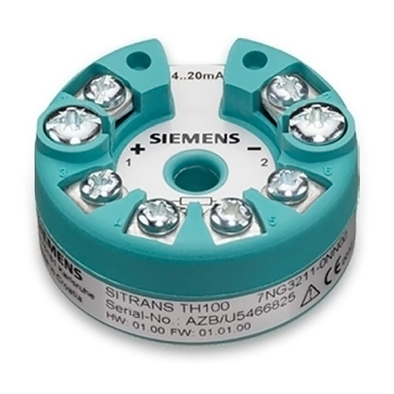
SITRANS TH100 4.1.1 Application range The SITRANS TH100 transmitter can be used in all fields. Its compact size means that it can be installed in connection heads of type B (DIN 43729) or larger. The following sensor can be connected: •... -
Page 32: Structure
Fixing screws for terminals 1 to 6 1 (+) Output terminals: Power supply U , output current I and 2 (-) 3, 4, 5, Input terminals for Pt100 and 6 Figure 4-1 SITRANS TH100 design SITRANS TH100/TH320/TH420/TR320/TR420/TF320/TF420 with 4 to 20 mA/HART Operating Instructions, 05/2020, A5E41864807-AB... -
Page 33: How Th100 Works
The signal prepared in this manner is then converted in a digital-to-analog converter into a load- independent direct current of 4 to 20 mA. The input and output circuits are each protected against electromagnetic interference through the use of EMC filters. SITRANS TH100/TH320/TH420/TR320/TR420/TF320/TF420 with 4 to 20 mA/HART Operating Instructions, 05/2020, A5E41864807-AB... -
Page 34: Sitrans Th320/Th420
The device meets the requirements of the EU Directive 2014/34/EU (ATEX), the FM and CSA regulations as well as other national approvals, e.g. EACEx, NEPSI, Inmetro. SITRANS TH100/TH320/TH420/TR320/TR420/TF320/TF420 with 4 to 20 mA/HART Operating Instructions, 05/2020, A5E41864807-AB... -
Page 35: Structure
3, 4, 5, 6, 7, 8 and 9 Input terminals TH420 ⑤ Mounting holes ⑥ ⑦ Mounting screw M4 ⑧ Lock washer DIN 6799 - 3.2 A2 Figure 4-3 SITRANS TH320/TH420 design SITRANS TH100/TH320/TH420/TR320/TR420/TF320/TF420 with 4 to 20 mA/HART Operating Instructions, 05/2020, A5E41864807-AB... -
Page 36: Meaning Of The Jumper Positions
⑥ Serial number First two digits = year of manufacture ⑦ Device version ⑧ Product name ⑨ Manufacturer Figure 4-4 Example of nameplate for SITRANS TH with approval information SITRANS TH100/TH320/TH420/TR320/TR420/TF320/TF420 with 4 to 20 mA/HART Operating Instructions, 05/2020, A5E41864807-AB... -
Page 37: Led Function
Operating state Color Device OK Green No power supply Display of faults independent of the device, Flashing e.g. wire break, sensor short circuit, violation of sensor limits Device error SITRANS TH100/TH320/TH420/TR320/TR420/TF320/TF420 with 4 to 20 mA/HART Operating Instructions, 05/2020, A5E41864807-AB... -
Page 38: Test Terminals
When using the test terminals, the temperature transmitter must be connected to the power supply. Figure 4-6 Test terminals Warning! Only use certified testing devices for installation in hazardous areas. SITRANS TH100/TH320/TH420/TR320/TR420/TF320/TF420 with 4 to 20 mA/HART Operating Instructions, 05/2020, A5E41864807-AB... -
Page 39: How Th320 Works
LED and the communications data is prepared. • The digital-to-analog converter (D/A) subsequently converts the signal into the output ④ current of 4 to 20 mA. SITRANS TH100/TH320/TH420/TR320/TR420/TF320/TF420 with 4 to 20 mA/HART Operating Instructions, 05/2020, A5E41864807-AB... -
Page 40: How Th420 Works
LED and the communications data is prepared. • The digital-to-analog converter (D/A) subsequently converts the signal into the output ④ current of 4 to 20 mA. SITRANS TH100/TH320/TH420/TR320/TR420/TF320/TF420 with 4 to 20 mA/HART Operating Instructions, 05/2020, A5E41864807-AB... -
Page 41: Hart Communication
Description 4.2 SITRANS TH320/TH420 4.2.9 HART communication 4.2.9.1 HART communication with supply from voltage source Figure 4-9 HART communication with supply from voltage source SITRANS TH100/TH320/TH420/TR320/TR420/TF320/TF420 with 4 to 20 mA/HART Operating Instructions, 05/2020, A5E41864807-AB... -
Page 42: Hart Communication With Supply Via Isolating Power Supply
Load ≥ 250 Ω only relevant if HART communication takes place via this branch. Otherwise, load of 0 to 650 Ω for ver‐ ① ② sions Figure 4-10 HART communication with supply via isolating power supply SITRANS TH100/TH320/TH420/TR320/TR420/TF320/TF420 with 4 to 20 mA/HART Operating Instructions, 05/2020, A5E41864807-AB... -
Page 43: Sitrans Tr320/Tr420
The device meets the requirements of the EU Directive 2014/34/EU (ATEX), the FM and CSA regulations as well as other national approvals, e.g. EACEx, NEPSI, Inmetro. SITRANS TH100/TH320/TH420/TR320/TR420/TF320/TF420 with 4 to 20 mA/HART Operating Instructions, 05/2020, A5E41864807-AB... -
Page 44: Structure
5, 6, 7, 8, 9, 10, 11 Input terminals TR420 and 12 ⑥ Extension port terminal number 1 Meaning of the jumper positions (Page 45) Figure 4-11 SITRANS TR320/TR420 design SITRANS TH100/TH320/TH420/TR320/TR420/TF320/TF420 with 4 to 20 mA/HART Operating Instructions, 05/2020, A5E41864807-AB... -
Page 45: Meaning Of The Jumper Positions
A fault current ≥ 21 mA is not permissible for operation of the device with functional safe‐ ty. Functional safety cannot be activated with a fault current ≥ 21 mA. SITRANS TH100/TH320/TH420/TR320/TR420/TF320/TF420 with 4 to 20 mA/HART Operating Instructions, 05/2020, A5E41864807-AB... -
Page 46: Nameplate Layout Sitrans Tr
Example of nameplate for SITRANS TR with approval information 4.3.5 LED function Description The integrated LED on the transmitter indicates errors according to NAMUR NE44 and NE107. State Operating state Color Device OK Green No power supply SITRANS TH100/TH320/TH420/TR320/TR420/TF320/TF420 with 4 to 20 mA/HART Operating Instructions, 05/2020, A5E41864807-AB... -
Page 47: Test Terminals
When using the test terminals, the temperature transmitter must be connected to the power supply. Figure 4-13 Test terminals Warning! Only use certified testing devices for installation in hazardous areas. SITRANS TH100/TH320/TH420/TR320/TR420/TF320/TF420 with 4 to 20 mA/HART Operating Instructions, 05/2020, A5E41864807-AB... -
Page 48: How Tr320 Works
LED and the communications data is prepared. • The digital-to-analog converter (D/A) subsequently converts the signal into the output ③ current of 4 to 20 mA. SITRANS TH100/TH320/TH420/TR320/TR420/TF320/TF420 with 4 to 20 mA/HART Operating Instructions, 05/2020, A5E41864807-AB... -
Page 49: How Tr420 Works
LED and the communications data is prepared. • The digital-to-analog converter (D/A) subsequently converts the signal into the output ③ current of 4 to 20 mA. SITRANS TH100/TH320/TH420/TR320/TR420/TF320/TF420 with 4 to 20 mA/HART Operating Instructions, 05/2020, A5E41864807-AB... -
Page 50: Hart Communication
Description 4.3 SITRANS TR320/TR420 4.3.9 HART communication 4.3.9.1 HART communication with supply from voltage source Figure 4-16 HART communication with supply from voltage source SITRANS TH100/TH320/TH420/TR320/TR420/TF320/TF420 with 4 to 20 mA/HART Operating Instructions, 05/2020, A5E41864807-AB... -
Page 51: Hart Communication With Supply Via Isolating Power Supply
Load ≥ 250 Ω only relevant if HART communication takes place via this branch. Otherwise, load of 0 to 650 Ω for ver‐ ① ② sions Figure 4-17 HART communication with supply via isolating power supply SITRANS TH100/TH320/TH420/TR320/TR420/TF320/TF420 with 4 to 20 mA/HART Operating Instructions, 05/2020, A5E41864807-AB... -
Page 52: Sitrans Tf320/Tf420
③ ⑦ Cable inlet, optionally with cable gland Electrical terminal compartment ④ ⑧ Ground terminal Fixing screws for the display holder Figure 4-18 SITRANS TF single chamber housing design SITRANS TH100/TH320/TH420/TR320/TR420/TF320/TF420 with 4 to 20 mA/HART Operating Instructions, 05/2020, A5E41864807-AB... -
Page 53: Nameplate Layout Sitrans Tf Single Chamber Housing
Place of manufacture ⑨ DEVICE Device version Manufacturer's address ④ ⑩ Observe the compact operating instruc‐ Product name tions Figure 4-19 Example of nameplate for SITRANS TF single chamber housing SITRANS TH100/TH320/TH420/TR320/TR420/TF320/TF420 with 4 to 20 mA/HART Operating Instructions, 05/2020, A5E41864807-AB... -
Page 54: Dual Chamber Housing Design
Rotating the display (Page 72) ⑥ ⑬ Mounting holes on the enclosure Nameplate ⑦ ⑭ Nameplate Screw for the cover over the buttons Figure 4-20 Installation of SITRANS TF dual chamber housing SITRANS TH100/TH320/TH420/TR320/TR420/TF320/TF420 with 4 to 20 mA/HART Operating Instructions, 05/2020, A5E41864807-AB... -
Page 55: Nameplate Layout Sitrans Tf Dual Chamber Housing
④ ⑩ Place of manufacture Article number ⑤ ⑪ Manufacturer's address Product name ⑥ Sensor type Figure 4-21 Example of nameplate for SITRANS TF dual chamber housing SITRANS TH100/TH320/TH420/TR320/TR420/TF320/TF420 with 4 to 20 mA/HART Operating Instructions, 05/2020, A5E41864807-AB... -
Page 56: How Tf320 Works
• The digital-to-analog converter (D/A) subsequently converts the signal into the output current of 4 to 20 mA. • The power supply source is located in the output signal circuit. SITRANS TH100/TH320/TH420/TR320/TR420/TF320/TF420 with 4 to 20 mA/HART Operating Instructions, 05/2020, A5E41864807-AB... -
Page 57: How Tf420 Works
• The digital-to-analog converter (D/A) subsequently converts the signal into the output current of 4 to 20 mA. • The power supply source is located in the output signal circuit. SITRANS TH100/TH320/TH420/TR320/TR420/TF320/TF420 with 4 to 20 mA/HART Operating Instructions, 05/2020, A5E41864807-AB... -
Page 58: Usb Modem And Siprom T
Improper use of the USB modem The USB modem and the connected devices can be damaged. • Only use the USB modem for parameter assignment of the named Siemens temperature transmitters. • Always use the SIPROM T parameter assignment software. -
Page 59: Meaning Of Leds On The Usb Modem
The firmware of the USB modem is being updated. All LEDs light up for The firmware of the USB modem was successfully updated. 3 s. See also Troubleshooting of USB modem (Page 192) SITRANS TH100/TH320/TH420/TR320/TR420/TF320/TF420 with 4 to 20 mA/HART Operating Instructions, 05/2020, A5E41864807-AB... - Page 60 Description 4.5 USB modem and SIPROM T SITRANS TH100/TH320/TH420/TR320/TR420/TF320/TF420 with 4 to 20 mA/HART Operating Instructions, 05/2020, A5E41864807-AB...
-
Page 61: Installing/Mounting
Observe the installation requirements according to IEC/EN 60079-11 Section 6.3.13. These requirements are met by the TF320 /420 temperature transmitters and the TS500 temperature sensor from Siemens. SITRANS TH100/TH320/TH420/TR320/TR420/TF320/TF420 with 4 to 20 mA/HART Operating Instructions, 05/2020, A5E41864807-AB... -
Page 62: Safety Information For Installation In "Non-Sparking Na/Ec" And "Intrinsic Safety Ic
In "Ex nA" and "Ex ec" areas, the transmitter/local display must be installed in an enclosure that ensures at least IP54 degree of protection according to IEC 60079-0. In addition, the enclosure SITRANS TH100/TH320/TH420/TR320/TR420/TF320/TF420 with 4 to 20 mA/HART Operating Instructions, 05/2020, A5E41864807-AB... -
Page 63: Fm/Csa
• The entity parameters Uo, Voc or Vt and Io, Isc or It, as well as Ca and La for barriers are communicated by the barrier manufacturer. SITRANS TH100/TH320/TH420/TR320/TR420/TF320/TF420 with 4 to 20 mA/HART Operating Instructions, 05/2020, A5E41864807-AB... -
Page 64: Safety Information For Installation In "Non Incendive Na
Voc < V , Ca ≥ Ci + C , La ≥ Li + L Cable Cable SITRANS TH100/TH320/TH420/TR320/TR420/TF320/TF420 with 4 to 20 mA/HART Operating Instructions, 05/2020, A5E41864807-AB... -
Page 65: Sitrans Tf
Installing SITRANS TH in a connection head 5.2.1 Installing the transmitter in the base of the connection head Condition The transmitter is only designed for installation in a type B connection head or larger. SITRANS TH100/TH320/TH420/TR320/TR420/TF320/TF420 with 4 to 20 mA/HART Operating Instructions, 05/2020, A5E41864807-AB... -
Page 66: Installing The Transmitter In The Raised Cover Of The Connection Head
Securing the transmitter in the connection head base 5.2.2 Installing the transmitter in the raised cover of the connection head Condition The transmitter is only designed for installation in a type B connection head or larger. SITRANS TH100/TH320/TH420/TR320/TR420/TF320/TF420 with 4 to 20 mA/HART Operating Instructions, 05/2020, A5E41864807-AB... -
Page 67: Installing Sitrans Th On Din Rail And G Rail
DIN rails and G rails in this context. The DIN/G rail adapter required for installation can be ordered as an accessory under the Order No. 7NG3092-8KA. Adhere to the ambient conditions specified in the technical data. SITRANS TH100/TH320/TH420/TR320/TR420/TF320/TF420 with 4 to 20 mA/HART Operating Instructions, 05/2020, A5E41864807-AB... -
Page 68: Installing Sitrans Tr On Din Rail
Installing SITRANS TR on DIN rail The transmitter is secured to a 35 mm DIN rail in accordance with DIN EN 60715. Comply with the ambient conditions specified in the technical data. SITRANS TH100/TH320/TH420/TR320/TR420/TF320/TF420 with 4 to 20 mA/HART Operating Instructions, 05/2020, A5E41864807-AB... -
Page 69: Mounting The Sitrans Tf Single Chamber Housing
2. Fasten the rail to the wall or to the pipe clamp. 5.5.2 Rotating the display To read the display in any mounting position, you can rotate it by 360° in 90° steps. SITRANS TH100/TH320/TH420/TR320/TR420/TF320/TF420 with 4 to 20 mA/HART Operating Instructions, 05/2020, A5E41864807-AB... -
Page 70: Mounting The Sitrans Tf Dual Chamber Housing
Mounting the SITRANS TF dual chamber housing 5.6.1 Mounting device to a pole with mounting bracket Introduction ② ① The mounting holes in the bracket and the device enclosure determine the permitted mounting positions. SITRANS TH100/TH320/TH420/TR320/TR420/TF320/TF420 with 4 to 20 mA/HART Operating Instructions, 05/2020, A5E41864807-AB... -
Page 71: Mounting Device To The Wall With Mounting Bracket
5.6.2 Mounting device to the wall with mounting bracket Introduction ② ① The mounting holes in the bracket and the device enclosure determine the permitted mounting positions. SITRANS TH100/TH320/TH420/TR320/TR420/TF320/TF420 with 4 to 20 mA/HART Operating Instructions, 05/2020, A5E41864807-AB... -
Page 72: Rotating The Display
To read the local display in any mounting position, you can rotate it incrementally 360°. Procedure 1. Use a 3 mm Allen key to loosen the front safety catch. 2. Unscrew the front cover. SITRANS TH100/TH320/TH420/TR320/TR420/TF320/TF420 with 4 to 20 mA/HART Operating Instructions, 05/2020, A5E41864807-AB... - Page 73 5. Mount the local display once again at the desired position. 6. Screw the front cover on as far as it will go. See also Dual chamber housing design (Page 54) Opening the device (Page 95) SITRANS TH100/TH320/TH420/TR320/TR420/TF320/TF420 with 4 to 20 mA/HART Operating Instructions, 05/2020, A5E41864807-AB...
-
Page 74: Mount Adapter M20X1.5-Pg13.5
② Flat seal ③ Adapter M20x1.5-PG13.5 ④ O-ring Mount adapter for connector socket Han7D/Han8D Tools • Torque wrench 35 width A/F • Screw retainer finish (for example, Loctite 270) SITRANS TH100/TH320/TH420/TR320/TR420/TF320/TF420 with 4 to 20 mA/HART Operating Instructions, 05/2020, A5E41864807-AB... - Page 75 4. Turn the adapter clockwise by hand until tight. 5. Tighten the adapter with a torque of 5 Nm (+1). 6. If necessary, adjust the position of the adapter until it is mounted in the following position: SITRANS TH100/TH320/TH420/TR320/TR420/TF320/TF420 with 4 to 20 mA/HART Operating Instructions, 05/2020, A5E41864807-AB...
-
Page 76: Removing
• If the device contains hazardous media, it must be emptied prior to disassembly. Make sure that no environmentally hazardous media are released. • Secure the remaining connections so that no damage can result if the process is started unintentionally. SITRANS TH100/TH320/TH420/TR320/TR420/TF320/TF420 with 4 to 20 mA/HART Operating Instructions, 05/2020, A5E41864807-AB... -
Page 77: Connecting
• Connect the device with type of protection "Intrinsic safety" solely to an intrinsically safe circuit. • Observe the specifications for the electrical data on the certificate and/or in Technical data (Page 193). SITRANS TH100/TH320/TH420/TR320/TR420/TF320/TF420 with 4 to 20 mA/HART Operating Instructions, 05/2020, A5E41864807-AB... - Page 78 • Devices having the type of protection "Intrinsic safety Ex i" may also be connected in energized state in hazardous areas. • Exceptions for type of protection "Non-sparking nA/ec" (Zone 2) are regulated in the relevant certificate. SITRANS TH100/TH320/TH420/TR320/TR420/TF320/TF420 with 4 to 20 mA/HART Operating Instructions, 05/2020, A5E41864807-AB...
-
Page 79: Connecting The Th100
2. Connect the supply voltage to the terminals 1 (+) and 2 (-). Take the polarity into account. The device has reverse polarity protection. See also SITRANS TH100 (Page 193) SITRANS TH100/TH320/TH420/TR320/TR420/TF320/TF420 with 4 to 20 mA/HART Operating Instructions, 05/2020, A5E41864807-AB... -
Page 80: Connecting Th320
2. Connect the supply voltage to the terminals 1 (+) and 2 (-). Take the polarity into account. The device has reverse polarity protection. TEST For devices with HART communication, connect a ≥ 250 Ω resistor. SITRANS TH100/TH320/TH420/TR320/TR420/TF320/TF420 with 4 to 20 mA/HART Operating Instructions, 05/2020, A5E41864807-AB... -
Page 81: Connecting Th420
Connecting 6.4 Connecting TH420 Connecting TH420 Requirement If you use stranded wire used, you need a ferrule. Note the maximum permissible core cross-section (Page 196). SITRANS TH100/TH320/TH420/TR320/TR420/TF320/TF420 with 4 to 20 mA/HART Operating Instructions, 05/2020, A5E41864807-AB... - Page 82 2. Connect the supply voltage to the terminals 1 (+) and 2 (-). Take the polarity into account. The device has reverse polarity protection. TEST For devices with HART communication, connect a ≥ 250 Ω resistor. SITRANS TH100/TH320/TH420/TR320/TR420/TF320/TF420 with 4 to 20 mA/HART Operating Instructions, 05/2020, A5E41864807-AB...
-
Page 83: Connecting Tr320
Connecting 6.5 Connecting TR320 Connecting TR320 Requirement If you use stranded wire used, you need a ferrule. Note the maximum permissible core cross-section (Page 196). SITRANS TH100/TH320/TH420/TR320/TR420/TF320/TF420 with 4 to 20 mA/HART Operating Instructions, 05/2020, A5E41864807-AB... - Page 84 2-wire or 3-wire CJC) I1: Input 1 Voltage input (unipolar and bi‐ 3-wire or 4-wire potentiometer polar) 2. Connect the supply voltage to the terminals 3 (+) and 4 (-). SITRANS TH100/TH320/TH420/TR320/TR420/TF320/TF420 with 4 to 20 mA/HART Operating Instructions, 05/2020, A5E41864807-AB...
-
Page 85: Connecting Tr420
3. Take the polarity into account. The device has reverse polarity protection. Connecting TR420 Requirement If you use stranded wire used, you need a ferrule. Note the maximum permissible core cross-section (Page 196). SITRANS TH100/TH320/TH420/TR320/TR420/TF320/TF420 with 4 to 20 mA/HART Operating Instructions, 05/2020, A5E41864807-AB... - Page 86 Input 1 (I1) and/or input 2 (I2): Input 1 and/or input 2: Voltage input 2-wire, 3-wire or 4-wire RTD or TC (int. CJC or (unipolar and bipolar) linear resistance ext. 2-wire or 3-wire CJC) SITRANS TH100/TH320/TH420/TR320/TR420/TF320/TF420 with 4 to 20 mA/HART Operating Instructions, 05/2020, A5E41864807-AB...
- Page 87 2. Connect the supply voltage to the terminals 3 (+) and 4 (-). For devices with HART communication, connect a ≥ 250 Ω resistor. 3. Take the polarity into account. The device has reverse polarity protection. SITRANS TH100/TH320/TH420/TR320/TR420/TF320/TF420 with 4 to 20 mA/HART Operating Instructions, 05/2020, A5E41864807-AB...
-
Page 88: Connecting The Sitrans Tf Single Chamber Housing
Connecting the SITRANS TF320 single chamber housing Condition The device is opened. (Page 88) If you use stranded wire used, you need a ferrule. Note the maximum permissible core cross-section (Page 196). SITRANS TH100/TH320/TH420/TR320/TR420/TF320/TF420 with 4 to 20 mA/HART Operating Instructions, 05/2020, A5E41864807-AB... - Page 89 6.7 Connecting the SITRANS TF single chamber housing Procedure 1. Remove the local display from the holder. ① 2. Loosen the fastening screws of the temperature transmitter and remove it. SITRANS TH100/TH320/TH420/TR320/TR420/TF320/TF420 with 4 to 20 mA/HART Operating Instructions, 05/2020, A5E41864807-AB...
- Page 90 Connecting TH320 (Page 80) ⑥ Figure 6-3 HART communication resistor (optional) 5. Insert the temperature transmitter and screw it into place. 6. Insert the local display. SITRANS TH100/TH320/TH420/TR320/TR420/TF320/TF420 with 4 to 20 mA/HART Operating Instructions, 05/2020, A5E41864807-AB...
-
Page 91: Connecting The Sitrans Tf420 Single Chamber Housing
Connecting the SITRANS TF420 single chamber housing Condition The device is opened. (Page 88) If you use stranded wire used, you need a ferrule. Note the maximum permissible core cross-section (Page 196). SITRANS TH100/TH320/TH420/TR320/TR420/TF320/TF420 with 4 to 20 mA/HART Operating Instructions, 05/2020, A5E41864807-AB... - Page 92 6.7 Connecting the SITRANS TF single chamber housing Procedure 1. Remove the local display from the holder. ① 2. Loosen the fastening screws of the temperature transmitter and remove it. SITRANS TH100/TH320/TH420/TR320/TR420/TF320/TF420 with 4 to 20 mA/HART Operating Instructions, 05/2020, A5E41864807-AB...
- Page 93 Connecting TH420 (Page 81) ⑥ Figure 6-4 HART communication resistor (optional) 5. Insert the temperature transmitter and screw it into place. 6. Insert the local display. SITRANS TH100/TH320/TH420/TR320/TR420/TF320/TF420 with 4 to 20 mA/HART Operating Instructions, 05/2020, A5E41864807-AB...
-
Page 94: Closing The Device
2. Use a 3 mm Allen key to secure the cover with the safety catch ③ 3. Check the tightness of the cable glands in accordance with the degree of protection. SITRANS TH100/TH320/TH420/TR320/TR420/TF320/TF420 with 4 to 20 mA/HART Operating Instructions, 05/2020, A5E41864807-AB... -
Page 95: Connecting The Sitrans Tf Dual Chamber Housing
Connecting the SITRANS TF320 dual chamber housing Requirement The device is opened. (Page 95) If you use stranded wire, you need a ferrule. Note the maximum permissible core cross-section (Page 196). SITRANS TH100/TH320/TH420/TR320/TR420/TF320/TF420 with 4 to 20 mA/HART Operating Instructions, 05/2020, A5E41864807-AB... - Page 96 The screw of the ground terminal is electrically connected to the external protective conductor connection. 5. For devices with intrinsic safety type of protection, use an isolating power supply that corresponds to the requirements of the relevant type of protection. SITRANS TH100/TH320/TH420/TR320/TR420/TF320/TF420 with 4 to 20 mA/HART Operating Instructions, 05/2020, A5E41864807-AB...
-
Page 97: Connecting The Sitrans Tf420 Dual Chamber Housing
Connecting the SITRANS TF420 dual chamber housing Requirement The device is opened. (Page 95) If you use stranded wire used, you need a ferrule. Note the maximum permissible core cross-section (Page 196). SITRANS TH100/TH320/TH420/TR320/TR420/TF320/TF420 with 4 to 20 mA/HART Operating Instructions, 05/2020, A5E41864807-AB... - Page 98 The screw of the ground terminal is electrically connected to the external protective conductor connection. 5. For devices with intrinsic safety type of protection, use an isolating power supply that corresponds to the requirements of the relevant type of protection. SITRANS TH100/TH320/TH420/TR320/TR420/TF320/TF420 with 4 to 20 mA/HART Operating Instructions, 05/2020, A5E41864807-AB...
- Page 99 2-wire or 3-wire CJC) input 2 (I2): Input 2: 2-wire, 3-wire or 4-wire 3-wire or 4-wire potentiometer Input 2 (I2): 3-wire potentiome‐ 7. Close the device. Closing the device (Page 100) SITRANS TH100/TH320/TH420/TR320/TR420/TF320/TF420 with 4 to 20 mA/HART Operating Instructions, 05/2020, A5E41864807-AB...
-
Page 100: Closing The Device
Note Observe the protection class of the Han plug when defining the protection class. The contact parts for the cable socket are supplied. SITRANS TH100/TH320/TH420/TR320/TR420/TF320/TF420 with 4 to 20 mA/HART Operating Instructions, 05/2020, A5E41864807-AB... -
Page 101: Connect M12 Cable Socket To The Cable
Note A conductive connection must not exist between the shield and the connector housing. Note Observe the protection class of the M12 device plug when defining the protection class. SITRANS TH100/TH320/TH420/TR320/TR420/TF320/TF420 with 4 to 20 mA/HART Operating Instructions, 05/2020, A5E41864807-AB... - Page 102 Reference edge for the dimension spec‐ Shrink sleeve ifications for cable assembly Assignment Assignment diagram M12-cable socket Layout for M12 device plug ① ① M12 x 1 thread Positioning slot ② Positioning catch SITRANS TH100/TH320/TH420/TR320/TR420/TF320/TF420 with 4 to 20 mA/HART Operating Instructions, 05/2020, A5E41864807-AB...
- Page 103 Connecting 6.10 Connect M12 cable socket to the cable Not connected Not connected Shield Shield Middle contact of the cable socket not connected SITRANS TH100/TH320/TH420/TR320/TR420/TF320/TF420 with 4 to 20 mA/HART Operating Instructions, 05/2020, A5E41864807-AB...
- Page 104 Connecting 6.10 Connect M12 cable socket to the cable SITRANS TH100/TH320/TH420/TR320/TR420/TF320/TF420 with 4 to 20 mA/HART Operating Instructions, 05/2020, A5E41864807-AB...
-
Page 105: Operating (Sitrans Tf)
7.1.1.1 Single chamber housing buttons The four buttons are located below the local display. To access the buttons, remove the cover. Figure 7-1 Single chamber housing with open cover SITRANS TH100/TH320/TH420/TR320/TR420/TF320/TF420 with 4 to 20 mA/HART Operating Instructions, 05/2020, A5E41864807-AB... -
Page 106: Dual Chamber Housing Buttons
Operating (SITRANS TF) 7.1 Local operation 7.1.1.2 Dual chamber housing buttons The four buttons are located below the cover: Figure 7-2 Top view SITRANS TH100/TH320/TH420/TR320/TR420/TF320/TF420 with 4 to 20 mA/HART Operating Instructions, 05/2020, A5E41864807-AB... -
Page 107: Operating The Device With Display
Navigating in the views You navigate in the views with the Buttons (Page 105) buttons: Figure 7-3 The colors represent three different views: Measured value view, parameter view and edit view SITRANS TH100/TH320/TH420/TR320/TR420/TF320/TF420 with 4 to 20 mA/HART Operating Instructions, 05/2020, A5E41864807-AB... -
Page 108: Measurement View
CURRENT OUT Analog current of the primary variable ELECTR TEMP Electronics temperature Navigating in the measurement view Requirement You have disabled the button lock. Disabling button lock (Page 158) SITRANS TH100/TH320/TH420/TR320/TR420/TF320/TF420 with 4 to 20 mA/HART Operating Instructions, 05/2020, A5E41864807-AB... -
Page 109: Parameter View
Set the lower range value of the primary variable UPPER RANGE Set upper range value of the primary variable DAMPING Damping value FUNCT SAFETY Enable and disable Functional Safety SITRANS TH100/TH320/TH420/TR320/TR420/TF320/TF420 with 4 to 20 mA/HART Operating Instructions, 05/2020, A5E41864807-AB... -
Page 110: Edit View
You change the parameter values in the edit view. Wizards are available for specific parameters. Parameter values There are various parameter values: • Enumerations (e.g. unit type) • Numerical values (e.g. damping) SITRANS TH100/TH320/TH420/TR320/TR420/TF320/TF420 with 4 to 20 mA/HART Operating Instructions, 05/2020, A5E41864807-AB... - Page 111 3. Change the parameter value with the button. To navigate faster, keep the button pressed. 4. Save the change with the button. Or, cancel the change with the button. SITRANS TH100/TH320/TH420/TR320/TR420/TF320/TF420 with 4 to 20 mA/HART Operating Instructions, 05/2020, A5E41864807-AB...
-
Page 112: Device Status Display
The following options are available to lock the device: • Enable write protection using switch. • Enable write protection using the User PIN. • Enable write protection using the button lock. SITRANS TH100/TH320/TH420/TR320/TR420/TF320/TF420 with 4 to 20 mA/HART Operating Instructions, 05/2020, A5E41864807-AB... -
Page 113: Enable Write Protection With Write Protection Switch
Figure 7-8 Enable write protection using the write protection switch Result When the write protection switch is set to the closed lock position, measured values and parameters can be read. SITRANS TH100/TH320/TH420/TR320/TR420/TF320/TF420 with 4 to 20 mA/HART Operating Instructions, 05/2020, A5E41864807-AB... -
Page 114: Enable The User Pin On The Display
2. In the parameter view, select the "Button lock" parameter. 3. Press the button. The "EDIT" symbol flashes. 4. Select ON with the button. 5. Use the button to confirm. SITRANS TH100/TH320/TH420/TR320/TR420/TF320/TF420 with 4 to 20 mA/HART Operating Instructions, 05/2020, A5E41864807-AB... - Page 115 • The display automatically returns to the measurement view. • The display automatically changes between the measured values every 12 seconds. • The symbol for button lock "LL" and the measured value ID are displayed alternately. SITRANS TH100/TH320/TH420/TR320/TR420/TF320/TF420 with 4 to 20 mA/HART Operating Instructions, 05/2020, A5E41864807-AB...
- Page 116 Operating (SITRANS TF) 7.3 Locking the device SITRANS TH100/TH320/TH420/TR320/TR420/TF320/TF420 with 4 to 20 mA/HART Operating Instructions, 05/2020, A5E41864807-AB...
-
Page 117: Commissioning
• Basic safety notes: Connecting (Page 77) • Basic safety notes: Commissioning (Page 117) Read the entire device manual in order to achieve the optimum performance of the device. SITRANS TH100/TH320/TH420/TR320/TR420/TF320/TF420 with 4 to 20 mA/HART Operating Instructions, 05/2020, A5E41864807-AB... -
Page 118: Commissioning Sitrans Th320 With 4 To 20 Ma
Installing the transmitter in the base of the connection head (Page 65) Installing SITRANS TH on DIN rail and G rail (Page 67) 3. Connect the device. Connecting TH320 (Page 80) SITRANS TH100/TH320/TH420/TR320/TR420/TF320/TF420 with 4 to 20 mA/HART Operating Instructions, 05/2020, A5E41864807-AB... -
Page 119: Commissioning Sitrans Th320 With Hart
Switching on the supply voltage (Page 128) 5. Wait for 2 seconds. After this startup time, the device is operational. 6. Wait 5 minutes to get exact measured values. SITRANS TH100/TH320/TH420/TR320/TR420/TF320/TF420 with 4 to 20 mA/HART Operating Instructions, 05/2020, A5E41864807-AB... -
Page 120: Commissioning Sitrans Th420 With Hart
7. If you want to change the factory settings, configure the device using remote operation. Assigning parameters using remote operation (Page 159) 8. Lock the device. Locking the SITRANS TH/TR device (Page 170) SITRANS TH100/TH320/TH420/TR320/TR420/TF320/TF420 with 4 to 20 mA/HART Operating Instructions, 05/2020, A5E41864807-AB... -
Page 121: Commissioning Sitrans Tr320 With 4 To 20 Ma
7. Wait 5 minutes to get exact measured values. 8. Lock the device. Locking the SITRANS TH/TR device (Page 170) Result The LED is lit green. Structure (Page 44) SITRANS TH100/TH320/TH420/TR320/TR420/TF320/TF420 with 4 to 20 mA/HART Operating Instructions, 05/2020, A5E41864807-AB... -
Page 122: Commissioning Sitrans Tr320 With Hart
7. If you want to change the factory settings, configure the device using remote operation. Assigning parameters using remote operation (Page 159) 8. Lock the device. Locking the SITRANS TH/TR device (Page 170) Result The LED is lit green. Structure (Page 44) SITRANS TH100/TH320/TH420/TR320/TR420/TF320/TF420 with 4 to 20 mA/HART Operating Instructions, 05/2020, A5E41864807-AB... -
Page 123: Commissioning Sitrans Tr420 With Hart
The LED is lit green. Structure (Page 44) Commissioning SITRANS TF320 single chamber housing with 4 to 20 mA Condition In this section, you will learn how to commission the device step-by-step. SITRANS TH100/TH320/TH420/TR320/TR420/TF320/TF420 with 4 to 20 mA/HART Operating Instructions, 05/2020, A5E41864807-AB... -
Page 124: Commissioning Sitrans Tf320 Single Chamber Housing With Hart
• Basic safety notes: Connecting (Page 77) • Basic safety notes: Commissioning (Page 117) Read the entire device manual in order to achieve the optimum performance of the device. SITRANS TH100/TH320/TH420/TR320/TR420/TF320/TF420 with 4 to 20 mA/HART Operating Instructions, 05/2020, A5E41864807-AB... -
Page 125: Commissioning Sitrans Tf420 Single Chamber Housing With Hart
3. For devices with intrinsically safe protection type, use an isolating power supply that corresponds to the requirements of the relevant type of protection. 4. Switch on the power supply. Switching on the supply voltage (Page 128) SITRANS TH100/TH320/TH420/TR320/TR420/TF320/TF420 with 4 to 20 mA/HART Operating Instructions, 05/2020, A5E41864807-AB... -
Page 126: 8.12 Commissioning Sitrans Tf320 Dual Chamber Housing With 4 To 20 Ma
Parameter assignment over device with display (Page 138) or Parameter assignment with USB modem and SIPROM T (Page 137) 7. Lock the device. Locking the SITRANS TF device (Page 173) SITRANS TH100/TH320/TH420/TR320/TR420/TF320/TF420 with 4 to 20 mA/HART Operating Instructions, 05/2020, A5E41864807-AB... -
Page 127: Commissioning Sitrans Tf320 Dual Chamber Housing With Hart
• Basic safety notes: Connecting (Page 77) • Basic safety notes: Commissioning (Page 117) Read the entire device manual in order to achieve the optimum performance of the device. SITRANS TH100/TH320/TH420/TR320/TR420/TF320/TF420 with 4 to 20 mA/HART Operating Instructions, 05/2020, A5E41864807-AB... -
Page 128: Switching On The Supply Voltage
For a device without a display, you read off the current output as follows: – Over the remote control (e.g. SIMATIC PDM). – With a DC current measuring device. SITRANS TH100/TH320/TH420/TR320/TR420/TF320/TF420 with 4 to 20 mA/HART Operating Instructions, 05/2020, A5E41864807-AB... -
Page 129: Commissioning The Usb Modem And Siprom T
4. Double-click the "setup.exe" file in the SIPROM T software directory. 5. Follow the installation instructions. 6. Download the following USB driver from the Internet: (http://www.ftdichip.com/ Drivers/CDM/CDM20830_Setup.exe) 7. Open the USB driver file. 8. Install the downloaded USB driver. SITRANS TH100/TH320/TH420/TR320/TR420/TF320/TF420 with 4 to 20 mA/HART Operating Instructions, 05/2020, A5E41864807-AB... - Page 130 8. In the menu, select "Device" > "Settings". 9. Select the noted COM port number from the Windows "Device Manager". 10.Click "OK". See also Uninstalling USB drivers (Page 179) SITRANS TH100/TH320/TH420/TR320/TR420/TF320/TF420 with 4 to 20 mA/HART Operating Instructions, 05/2020, A5E41864807-AB...
-
Page 131: Connecting Usb Modem
Connecting cable to the temperature transmitter Red cable plus Black cable minus ④ USB cable ⑤ SITRANS TH100slim ⑥ Contact 1 plus Contact 3 minus Figure 8-2 Connecting USB modem SITRANS TH100/TH320/TH420/TR320/TR420/TF320/TF420 with 4 to 20 mA/HART Operating Instructions, 05/2020, A5E41864807-AB... - Page 132 ② ① ④ 1. Connect the USB modem to your PC using the USB cable ③ 2. Connect the USB modem to the temperature transmitter using the connecting cable SITRANS TH100/TH320/TH420/TR320/TR420/TF320/TF420 with 4 to 20 mA/HART Operating Instructions, 05/2020, A5E41864807-AB...
-
Page 133: Parameter Assignment
Set upper range value Lower range current "Settings > Current output" parameter group Upper range current Set damping value "Settings > Damping value [11] (Page 149) Sensor settings" parameter group SITRANS TH100/TH320/TH420/TR320/TR420/TF320/TF420 with 4 to 20 mA/HART Operating Instructions, 05/2020, A5E41864807-AB... - Page 134 "Maintenance and diagnostics > Drift de‐ tection" parameter group Display of the diagnostics Menu command "Diagnostics > Diagnos‐ tics" Limit monitoring and event counter Menu command "Diagnostics > Device status" SITRANS TH100/TH320/TH420/TR320/TR420/TF320/TF420 with 4 to 20 mA/HART Operating Instructions, 05/2020, A5E41864807-AB...
- Page 135 Menu command "Device > Device re‐ start" Factory reset Menu command "Device > Reset > Factory reset" Reset to sensor calibration Menu command "Device > Reset > Reset to sensor calibration" SITRANS TH100/TH320/TH420/TR320/TR420/TF320/TF420 with 4 to 20 mA/HART Operating Instructions, 05/2020, A5E41864807-AB...
-
Page 136: Advanced Functions
Peak values - Sensors The recording of the min./max. measured values of the sensor(s) is saved. When the measurement configuration is changed, the values are reset. SITRANS TH100/TH320/TH420/TR320/TR420/TF320/TF420 with 4 to 20 mA/HART Operating Instructions, 05/2020, A5E41864807-AB... -
Page 137: Parameter Assignment With Usb Modem And Siprom T
9. Wait at least 2 seconds before you disconnect the temperature transmitter. See also Identification (Page 160) User-specific type (Page 160) Set the linearization table (60 breakpoints) (Page 162) Set the spline curve (40 breakpoints) (Page 162) SITRANS TH100/TH320/TH420/TR320/TR420/TF320/TF420 with 4 to 20 mA/HART Operating Instructions, 05/2020, A5E41864807-AB... -
Page 138: Parameter Assignment Over Device With Display
TC Type T - IEC 584 TC L TC Type L - IEC 584 TC U TC Type U - DIN 43710 Factory setting: P100I Pt100 - IEC 751 SITRANS TH100/TH320/TH420/TR320/TR420/TF320/TF420 with 4 to 20 mA/HART Operating Instructions, 05/2020, A5E41864807-AB... - Page 139 Parameter assignment 9.3 Parameter assignment over device with display You can select all input types via remote operation. SITRANS TH100/TH320/TH420/TR320/TR420/TF320/TF420 with 4 to 20 mA/HART Operating Instructions, 05/2020, A5E41864807-AB...
- Page 140 RTD Cu100 – GOST 6651-1994 (α = 0.00426) (α = 0.00426) RTD Cux – GOST 6651-1994 CUX G RTD Cux – GOST 6651-1994 (α = 0.00426) (α = 0.00426) SITRANS TH100/TH320/TH420/TR320/TR420/TF320/TF420 with 4 to 20 mA/HART Operating Instructions, 05/2020, A5E41864807-AB...
- Page 141 Thermocouple Type W5 - ASTM E 988 Custom type CUSTM Custom type Factory set‐ RTD Pt100 - IEC 751 P100I Pt100 - IEC 751 ting: Value x matches customer RTD value SITRANS TH100/TH320/TH420/TR320/TR420/TF320/TF420 with 4 to 20 mA/HART Operating Instructions, 05/2020, A5E41864807-AB...
-
Page 142: Connection Type For Input 1 [02]
TC L Thermocouple Type L IEC 584 Factory setting: NONE No input type selected Can only be selected when the input type TC was also selected for input 1. SITRANS TH100/TH320/TH420/TR320/TR420/TF320/TF420 with 4 to 20 mA/HART Operating Instructions, 05/2020, A5E41864807-AB... - Page 143 Parameter assignment 9.3 Parameter assignment over device with display You can select all input types via remote operation. SITRANS TH100/TH320/TH420/TR320/TR420/TF320/TF420 with 4 to 20 mA/HART Operating Instructions, 05/2020, A5E41864807-AB...
- Page 144 CUX G RTD Cux – GOST 6651-1994 (α = 0.00426) 0.00426) RTD Nix – GOST 6651-2009 (α = NIX G RTD Nix – GOST 6651-2009 (α = 0.00617) 0.00617) SITRANS TH100/TH320/TH420/TR320/TR420/TF320/TF420 with 4 to 20 mA/HART Operating Instructions, 05/2020, A5E41864807-AB...
-
Page 145: Connection Type For Input 2 [05]
Connection type for input 2 [05] Selects the connection type for input 2 depending on the selected sensor. Indication on the dis‐ WIRING 2 play Setting range: 2, 3, 4-wire Factory setting: SITRANS TH100/TH320/TH420/TR320/TR420/TF320/TF420 with 4 to 20 mA/HART Operating Instructions, 05/2020, A5E41864807-AB... -
Page 146: Wire Resistance For Connecting Cable At Input 2 [06]
Average input 1 and input 2 with both as backup MIN B Minimum input 1 or input 2 with both as backup MAX B Maximum input 1 or input 2 with both as backup ETEMP Electronics temperature SITRANS TH100/TH320/TH420/TR320/TR420/TF320/TF420 with 4 to 20 mA/HART Operating Instructions, 05/2020, A5E41864807-AB... -
Page 147: Setting The Assignment Of The Primary Variable
Setting range: °C °F °R Factory setting: °C You can select additional units with the remote operation that are to be displayed in the measurement view. SITRANS TH100/TH320/TH420/TR320/TR420/TF320/TF420 with 4 to 20 mA/HART Operating Instructions, 05/2020, A5E41864807-AB... -
Page 148: Lower Range Value [09]/Upper Range Value [10]
Technical data (Page 193). Procedure 1. Navigate to the parameter view. Navigating in the views (Page 107) 2. In the parameter view, select the "Set lower range value" parameter. SITRANS TH100/TH320/TH420/TR320/TR420/TF320/TF420 with 4 to 20 mA/HART Operating Instructions, 05/2020, A5E41864807-AB... -
Page 149: Damping Value [11]
9.3.10.2 Set damping value Procedure 1. Navigate to the parameter view. Navigating in the views (Page 107) 2. Select the "Damping value" parameter. SITRANS TH100/TH320/TH420/TR320/TR420/TF320/TF420 with 4 to 20 mA/HART Operating Instructions, 05/2020, A5E41864807-AB... -
Page 150: Functional Safety [12]
Factory setting: 12 mA 9.3.12.1 Loop test with preset loop current value 1. Navigate into the parameter view. Navigating in the views (Page 107) 2. Select the parameter "Loop test". SITRANS TH100/TH320/TH420/TR320/TR420/TF320/TF420 with 4 to 20 mA/HART Operating Instructions, 05/2020, A5E41864807-AB... -
Page 151: Loop Test With User Defined Loop Current Value
6. Set a value between 3.6 mA and 22.8 mA using the buttons 7. Use the button to confirm. The loop test starts. 8. End the loop test with the button. SITRANS TH100/TH320/TH420/TR320/TR420/TF320/TF420 with 4 to 20 mA/HART Operating Instructions, 05/2020, A5E41864807-AB... -
Page 152: One-Point Calibration Input 1 [14]
Change User PIN [16] 9.3.15.1 Change user PIN Used to change the User PIN. Setting range: 1 to 65535 Factory setting: 2457 Requirement The "User PIN (Page 155)" parameter is enabled. SITRANS TH100/TH320/TH420/TR320/TR420/TF320/TF420 with 4 to 20 mA/HART Operating Instructions, 05/2020, A5E41864807-AB... -
Page 153: Pin Recovery [17]
Then repeat the described procedure. 9.3.16 PIN recovery [17] Used to reset the user PIN to the factory setting. The user PIN is factory set to 2457 in the device. SITRANS TH100/TH320/TH420/TR320/TR420/TF320/TF420 with 4 to 20 mA/HART Operating Instructions, 05/2020, A5E41864807-AB... -
Page 154: Recovering The User Pin
• If you have entered the correct PUK, the message "NEW PIN - 2457" appears. The user PIN has been reset to the factory setting 2457. • If the PUK was not correctly entered, the message "FAILD" appears. Then repeat the described procedure. SITRANS TH100/TH320/TH420/TR320/TR420/TF320/TF420 with 4 to 20 mA/HART Operating Instructions, 05/2020, A5E41864807-AB... -
Page 155: User Pin [18]
The message "USER PIN ON" (User PIN enabled) appears for 2 seconds. Result The User PIN is activated after about 10 minutes or after a device restart. 9.3.17.3 Disable user PIN Requirement The user PIN is enabled. SITRANS TH100/TH320/TH420/TR320/TR420/TF320/TF420 with 4 to 20 mA/HART Operating Instructions, 05/2020, A5E41864807-AB... -
Page 156: Minimum Measured Peak Value At Input 1 [19]
MIN INPUT 1 play 9.3.19 Maximum measured peak value at Input 1 [20] Shows the maximum measured peak value at input 1. Indication on the dis‐ MAX INPUT 1 play SITRANS TH100/TH320/TH420/TR320/TR420/TF320/TF420 with 4 to 20 mA/HART Operating Instructions, 05/2020, A5E41864807-AB... -
Page 157: Minimum Measured Peak Value At Input 2 [21]
9.3.24 Button lock [25] Enables the button lock. You can continue to operate the device using remote operation. Setting range: Button lock enabled Button lock disabled Factory setting: SITRANS TH100/TH320/TH420/TR320/TR420/TF320/TF420 with 4 to 20 mA/HART Operating Instructions, 05/2020, A5E41864807-AB... -
Page 158: Enabling Button Lock
To disable the button lock, press and hold the button for 5 seconds. Result • The symbol for Button lock "LL" is hidden. • You can operate the device using the buttons. SITRANS TH100/TH320/TH420/TR320/TR420/TF320/TF420 with 4 to 20 mA/HART Operating Instructions, 05/2020, A5E41864807-AB... -
Page 159: Assigning Parameters Using Remote Operation
• Step 6: Summary The summary provides an overview of the "old" and "new" parameters. To store the parameters in SIMATIC PDM and transfer them to the device, click the "Apply" button. SITRANS TH100/TH320/TH420/TR320/TR420/TF320/TF420 with 4 to 20 mA/HART Operating Instructions, 05/2020, A5E41864807-AB... -
Page 160: Identification
User-specific type 9.4.4.1 Introduction For special applications, a user-specific type is available. There is no internal validation check in the Engineering System. Test the expected functionality for your application. SITRANS TH100/TH320/TH420/TR320/TR420/TF320/TF420 with 4 to 20 mA/HART Operating Instructions, 05/2020, A5E41864807-AB... - Page 161 Enter the minimum and maximum X-value. The x values are distributed evenly on the x axis according to the desired number of breakpoints. You can freely assign the y values. Figure 9-2 Spline curve SITRANS TH100/TH320/TH420/TR320/TR420/TF320/TF420 with 4 to 20 mA/HART Operating Instructions, 05/2020, A5E41864807-AB...
-
Page 162: Set The Linearization Table (60 Breakpoints)
You use the one-point calibration to set the device characteristic at the low calibration point. You use the two-point calibration to set the device characteristic at the low and high calibration point. The results are correct measured values at the calibration points. SITRANS TH100/TH320/TH420/TR320/TR420/TF320/TF420 with 4 to 20 mA/HART Operating Instructions, 05/2020, A5E41864807-AB... -
Page 163: Setting One-Point Calibration
6. When your measured value is stable, assign the measured value to the low calibration point of the device. Result The device calibrates to the measured value. The device moves the characteristic by the difference between the original and the new calibration point. SITRANS TH100/TH320/TH420/TR320/TR420/TF320/TF420 with 4 to 20 mA/HART Operating Instructions, 05/2020, A5E41864807-AB... -
Page 164: Setting Two-Point Calibration
5. Confirm the warnings. 6. When your measured value is stable, assign the measured value to the low calibration point of the device. 7. Repeat the process for the high calibration point. SITRANS TH100/TH320/TH420/TR320/TR420/TF320/TF420 with 4 to 20 mA/HART Operating Instructions, 05/2020, A5E41864807-AB... -
Page 165: Transmitter Sensor Matching
You can change the calibration points R0, A, B, C, Alpha, Beta and Delta using the remote operation. SITRANS TH100/TH320/TH420/TR320/TR420/TF320/TF420 with 4 to 20 mA/HART Operating Instructions, 05/2020, A5E41864807-AB... -
Page 166: Changing The Callendar-Van Dusen Coefficients
• Operating hours counter and temperature ranges cannot be reset or set by the user. • The operating hours counter is only updated as long as the device is in measuring mode. The operating hours counter is not updated in simulation mode. SITRANS TH100/TH320/TH420/TR320/TR420/TF320/TF420 with 4 to 20 mA/HART Operating Instructions, 05/2020, A5E41864807-AB... -
Page 167: Current Output
Lower fault current parameter ② Adjusts the magnitude of the lower fault current ③ Setting range: Between 3.55 mA and lower saturation limit Factory setting: 3.55 mA, or as specified in order SITRANS TH100/TH320/TH420/TR320/TR420/TF320/TF420 with 4 to 20 mA/HART Operating Instructions, 05/2020, A5E41864807-AB... -
Page 168: Lower Saturation Limit Parameter
Setting the fault current of the internal transmitter with switch to ≥ 21 mA (Page 175) 9.4.9.2 Lower saturation limit parameter ③ Sets the lower threshold for the lower saturation limit SITRANS TH100/TH320/TH420/TR320/TR420/TF320/TF420 with 4 to 20 mA/HART Operating Instructions, 05/2020, A5E41864807-AB... -
Page 169: Upper Saturation Limit Parameter
4 mA ① Normal operation ② Lower fault current (factory setting) ③ Lower saturation limit (factory setting) ④ Upper saturation limit (factory setting) ⑤ Upper fault current (factory setting) SITRANS TH100/TH320/TH420/TR320/TR420/TF320/TF420 with 4 to 20 mA/HART Operating Instructions, 05/2020, A5E41864807-AB... -
Page 170: Locking The Device
Devices with functional safety To enable functional safety, first enable the user PIN. 9.5.1.2 Enable SITRANS TH write protection with jumper Introduction The jumper is used for enabling write protection. SITRANS TH100/TH320/TH420/TR320/TR420/TF320/TF420 with 4 to 20 mA/HART Operating Instructions, 05/2020, A5E41864807-AB... -
Page 171: Enable Sitrans Tr Write Protection With Jumper
When the jumper is set, only the measured values and the parameters can be read. 9.5.1.3 Enable SITRANS TR write protection with jumper Introduction The jumper is used for enabling write protection. SITRANS TH100/TH320/TH420/TR320/TR420/TF320/TF420 with 4 to 20 mA/HART Operating Instructions, 05/2020, A5E41864807-AB... - Page 172 SITRANS TH: Enable write protection using the jumper Meaning of the jumper positions (Page 45) Result When the jumper is set, only the measured values and the parameters can be read. SITRANS TH100/TH320/TH420/TR320/TR420/TF320/TF420 with 4 to 20 mA/HART Operating Instructions, 05/2020, A5E41864807-AB...
-
Page 173: User Pin Parameter
Devices with functional safety To enable functional safety, first enable the User PIN. 9.5.2.2 Enable write protection with write protection switch Introduction The write protection switch is used for enabling write protection. SITRANS TH100/TH320/TH420/TR320/TR420/TF320/TF420 with 4 to 20 mA/HART Operating Instructions, 05/2020, A5E41864807-AB... -
Page 174: Enable The User Pin On The Display
Navigating in the views (Page 107) 2. Select the parameter "User PIN". 3. Use the button to confirm. The message "USER PIN ON" (User PIN enabled) appears for 2 seconds. Result SITRANS TH100/TH320/TH420/TR320/TR420/TF320/TF420 with 4 to 20 mA/HART Operating Instructions, 05/2020, A5E41864807-AB... -
Page 175: Enable The Button Lock On The Display
A fault current ≥ 21 mA is not permissible for operation of the device with functional safety. Functional safety cannot be activated with a fault current ≥ 21 mA. SITRANS TH100/TH320/TH420/TR320/TR420/TF320/TF420 with 4 to 20 mA/HART Operating Instructions, 05/2020, A5E41864807-AB... - Page 176 Figure 9-7 Set the upper fault current using switch Result When the switch is in the HI position, the upper fault current is enabled. See also Current output (Page 167) SITRANS TH100/TH320/TH420/TR320/TR420/TF320/TF420 with 4 to 20 mA/HART Operating Instructions, 05/2020, A5E41864807-AB...
-
Page 177: Service And Maintenance
WARNING Dust layers above 5 mm Risk of explosion in hazardous areas. Device may overheat due to dust build up. • Remove dust layers in excess of 5 mm. SITRANS TH100/TH320/TH420/TR320/TR420/TF320/TF420 with 4 to 20 mA/HART Operating Instructions, 05/2020, A5E41864807-AB... -
Page 178: Cleaning
Electrostatic charge Risk of explosion in hazardous areas if electrostatic charges develop, for example, when cleaning plastic surfaces with a dry cloth. • Prevent electrostatic charging in hazardous areas. SITRANS TH100/TH320/TH420/TR320/TR420/TF320/TF420 with 4 to 20 mA/HART Operating Instructions, 05/2020, A5E41864807-AB... -
Page 179: Maintenance And Repair Work
10.3 Maintenance and repair work WARNING Impermissible repair and maintenance of the device • Repair and maintenance must be carried out by Siemens authorized personnel only. WARNING Impermissible repair of explosion protected devices Risk of explosion in hazardous areas • Repair must be carried out by Siemens authorized personnel only. - Page 180 3. Select "Uninstall" from the shortcut menu. 4. Select "USB Controller" > "USB Serial Converter" in the Windows Device Manager. 5. Right-click on "USB Serial Converter". 6. Select "Uninstall" from the shortcut menu. SITRANS TH100/TH320/TH420/TR320/TR420/TF320/TF420 with 4 to 20 mA/HART Operating Instructions, 05/2020, A5E41864807-AB...
-
Page 181: Sitrans Tf
10.3.2 SITRANS TF WARNING Impermissible repair and maintenance of the device • Repair and maintenance must be carried out by Siemens authorized personnel only. WARNING Impermissible repair of explosion protected devices Risk of explosion in hazardous areas • Repair must be carried out by Siemens authorized personnel only. -
Page 182: Replace Sitrans Tf Single Chamber Housing Local Display
1. De-energize the device. 2. Open the device. Opening the device (Page 88) 3. Remove the local display from the holder. 4. Disconnect the cable from the local display. SITRANS TH100/TH320/TH420/TR320/TR420/TF320/TF420 with 4 to 20 mA/HART Operating Instructions, 05/2020, A5E41864807-AB... -
Page 183: Installing The Display
GB/T 26572. 10.5 Return procedure Enclose the bill of lading, return document and decontamination certificate in a clear plastic pouch and attach it firmly to the outside of the packaging. SITRANS TH100/TH320/TH420/TR320/TR420/TF320/TF420 with 4 to 20 mA/HART Operating Instructions, 05/2020, A5E41864807-AB... -
Page 184: Disposal
Information on battery/product return (WEEE) (https:// support.industry.siemens.com/cs/document/109479891/) Note Special disposal required The device includes components that require special disposal. • Dispose of the device properly and environmentally through a local waste disposal contractor. SITRANS TH100/TH320/TH420/TR320/TR420/TF320/TF420 with 4 to 20 mA/HART Operating Instructions, 05/2020, A5E41864807-AB... -
Page 185: Diagnostics And Troubleshooting
– Local display (using Namur symbols) will show "Configuration error" as higher priority. – SIMATIC PDM (using Siemens standard symbols) will show "Maintenance demanded" as higher priority. Be aware of the priority for each device status, depending on the interface used. - Page 186 Process or ambient conditions can damage the device or result in unreliable results. Measure: Check ambient temperature or process conditions. If possible, install device at different location. SITRANS TH100/TH320/TH420/TR320/TR420/TF320/TF420 with 4 to 20 mA/HART Operating Instructions, 05/2020, A5E41864807-AB...
- Page 187 Measure: No action required. * The smallest number indicates the highest level of error severity. ** In SIMATIC PDM, the Siemens standard symbol as well as the corresponding NA\ symbol is displayed (by the device display). SITRANS TH100/TH320/TH420/TR320/TR420/TF320/TF420 with 4 to 20 mA/HART...
-
Page 188: Diagnostic Messages
Drift detected, reference volt‐ A critical measurement error was detected at the internal voltage age FVR reference. Reconnect or repair the sensor. If the problem persists, contact Technical Support. SITRANS TH100/TH320/TH420/TR320/TR420/TF320/TF420 with 4 to 20 mA/HART Operating Instructions, 05/2020, A5E41864807-AB... - Page 189 The device is in simulation mode and one or more of its device varia‐ bles are not representative of the process. Disable the simulation to return to normal operation. SITRANS TH100/TH320/TH420/TR320/TR420/TF320/TF420 with 4 to 20 mA/HART Operating Instructions, 05/2020, A5E41864807-AB...
- Page 190 Loop current read back error The loop current does not correspond to the expected value. Check DAC trim settings. Restore to factory DAC calibration. If the problem persists, contact Technical Support. SITRANS TH100/TH320/TH420/TR320/TR420/TF320/TF420 with 4 to 20 mA/HART Operating Instructions, 05/2020, A5E41864807-AB...
- Page 191 Check the error in menu "Diagnostics" in tab "Extended field device status". Validate the functional safety configuration or reselect normal oper‐ ation. If the device does not display an error, repeat the safety start up. SITRANS TH100/TH320/TH420/TR320/TR420/TF320/TF420 with 4 to 20 mA/HART Operating Instructions, 05/2020, A5E41864807-AB...
-
Page 192: Troubleshooting
USB modem is defective. Replace the USB module. See also Meaning of LEDs on the USB modem (Page 59) SITRANS TH100/TH320/TH420/TR320/TR420/TF320/TF420 with 4 to 20 mA/HART Operating Instructions, 05/2020, A5E41864807-AB... -
Page 193: Technical Data
Accuracy at 23 °C < 0.1% of measuring span Temperature influence Max. 0.1% / 10 °C (0.1% / 18 °F) Power supply influence < 0.01% of measuring span / V SITRANS TH100/TH320/TH420/TR320/TR420/TF320/TF420 with 4 to 20 mA/HART Operating Instructions, 05/2020, A5E41864807-AB... - Page 194 EN 61000-4-6 Table 12-1 Mechanical construction Core cross-section Max. 2.5 mm (AWG 13) Weight 50 g Dimensions See SITRANS TH100 dimension drawings (Page 217) Material Molded plastic Degree of protection In accordance with IEC 60529 • Housing IP40 IP00 •...
- Page 195 IS Cl I, II, III, Div 1, GP ABCDEFG T4/T5/T6 Cl I, ZN 0 Ex ia IIC T4/T5/T6 NI, S Cl I, II, III, Div 2, GP ABCDFG T4/T5/T6 NI IIC T4/T5/T6 SITRANS TH100/TH320/TH420/TR320/TR420/TF320/TF420 with 4 to 20 mA/HART Operating Instructions, 05/2020, A5E41864807-AB...
-
Page 196: Sitrans Th320/Th420/Tr320/Tr420/Tf320/Tf420
2.5 mm (AWG 14) Tightening torque for 0.4 Nm 0.5 ... 0.6 Nm screw terminals Vibration IEC 60068-2-6 2 Hz to 25 Hz 1.6 mm 25 Hz to 100 Hz SITRANS TH100/TH320/TH420/TR320/TR420/TF320/TF420 with 4 to 20 mA/HART Operating Instructions, 05/2020, A5E41864807-AB... -
Page 197: General Specifications
Basic values Input type Basic accuracy Temperature coefficient Pt10 ≤ ±0.8 °C ≤ ±0.020 °C/°C Pt20 ≤ ±0.4 °C ≤ ±0.010 °C/°C Pt50 ≤ ±0.16 °C ≤ ±0.004 °C/°C SITRANS TH100/TH320/TH420/TR320/TR420/TF320/TF420 with 4 to 20 mA/HART Operating Instructions, 05/2020, A5E41864807-AB... - Page 198 -100 ... 1700 mV ≤ ±0.1 mV ≤ ±36 μV/°C ≤ ± 0.01% of the value mV: ±800 mV ≤ ±0.1 mV ≤ ±32 μV/°C ≤ ± 0.01% of the value SITRANS TH100/TH320/TH420/TR320/TR420/TF320/TF420 with 4 to 20 mA/HART Operating Instructions, 05/2020, A5E41864807-AB...
- Page 199 CJC (external) ≤ ±0.08 °C ≤ ±0.002 °C/°C Temperature coefficients of the inputs correspond to the specified values or 0.002% of the input span, depending on which value is greater. SITRANS TH100/TH320/TH420/TR320/TR420/TF320/TF420 with 4 to 20 mA/HART Operating Instructions, 05/2020, A5E41864807-AB...
-
Page 200: Output Accuracies
0.1 ... 1% of the measuring range 0.1 ... 0.6% of the meas‐ on test according to IEC/EN uring range 61326-1 See also Accuracy calculation examples (Page 225) Product documentation (Page 221) SITRANS TH100/TH320/TH420/TR320/TR420/TF320/TF420 with 4 to 20 mA/HART Operating Instructions, 05/2020, A5E41864807-AB... -
Page 201: Input
+1820 °C 100 °C IEC 60584-1 -200 °C +1000 °C 50 °C IEC 60584-1 -100 °C +1200 °C 50 °C IEC 60584-1 -180 °C +1372 °C 50 °C IEC 60584-1 SITRANS TH100/TH320/TH420/TR320/TR420/TF320/TF420 with 4 to 20 mA/HART Operating Instructions, 05/2020, A5E41864807-AB... -
Page 202: Linear Resistance
2-wire, 3-wire or 4-wire Wire resistance per wire (max.) 50 Ω Input current < 0.15 mA Effect of the wire resistance (with 3-wire < 0.002 Ω/Ω or 4-wire connections) SITRANS TH100/TH320/TH420/TR320/TR420/TF320/TF420 with 4 to 20 mA/HART Operating Instructions, 05/2020, A5E41864807-AB... -
Page 203: Potentiometer
Max. 30 nF (input range: -100 ... 1700 mV) Max. 50 nF (input range: -20 ... 100 mV) Error detection, programmable None, broken Error detection time ≤ 75 ms (typically 70 ms) SITRANS TH100/TH320/TH420/TR320/TR420/TF320/TF420 with 4 to 20 mA/HART Operating Instructions, 05/2020, A5E41864807-AB... -
Page 204: Output Specifications And Hart
IECEx DEK 19.0069X IECEx DEK19.0068X ГОСТ 31610.0-2014 № TC RU C–DE.AA87.В.01162 № TC RU C–DE.xxxx.x.xxxxx (IEC 60079-0:2011) ОС НАНИО «ЦСВЭ» ОС НАНИО «ЦСВЭ» ГОСТ 31610.11-2014 (IEC 60079-11:2011) ГОСТ 31610.15-2014/ IEC 60079-15:2010 SITRANS TH100/TH320/TH420/TR320/TR420/TF320/TF420 with 4 to 20 mA/HART Operating Instructions, 05/2020, A5E41864807-AB... - Page 205 T5 class T5 -50 °C to +55 °C -40 °C to +55 °C (-58 °F to +131 °F) temperature (-40 °F to +131°F) temperature class T6 class T6 SITRANS TH100/TH320/TH420/TR320/TR420/TF320/TF420 with 4 to 20 mA/HART Operating Instructions, 05/2020, A5E41864807-AB...
- Page 206 = 2.2 nF Ui = 30 V DC, Li = 0 μH, Ci = 1.0 nF 2.2 nF SITRANS TH/ SITRANS TF single chamber housing: 1, 2 SITRANS TR: 3, 4 SITRANS TF dual cham‐ ber housing: (+) and SITRANS TH100/TH320/TH420/TR320/TR420/TF320/TF420 with 4 to 20 mA/HART Operating Instructions, 05/2020, A5E41864807-AB...
- Page 207 -50 °C to +75 °C Temperature class T6 Temperature class T6 (-58 °F to +167 °F) temperature class T5 -50 °C to +60 °C (-58 °F to +140 °F) temperature class T6 SITRANS TH100/TH320/TH420/TR320/TR420/TF320/TF420 with 4 to 20 mA/HART Operating Instructions, 05/2020, A5E41864807-AB...
- Page 208 SITRANS TF with local display -40 °C A SITRANS TF display or a SITRANS TF in a dual chamber housing has the minimum permissible ambient temperature of -40 °C. See also Certificates (http://www.siemens.com/processinstrumentation/certificates) SITRANS TH100/TH320/TH420/TR320/TR420/TF320/TF420 with 4 to 20 mA/HART Operating Instructions, 05/2020, A5E41864807-AB...
-
Page 209: Fm/Csa
UL Std No. 913, Ed. 8 UL 60079-0, Ed 5 UL 60079-11, Ed. 6 UL 60079-15, Ed. 4 UL 61010-1 Ed. 3 • "Intrinsic safety ia" type of protection SITRANS TH100/TH320/TH420/TR320/TR420/TF320/TF420 with 4 to 20 mA/HART Operating Instructions, 05/2020, A5E41864807-AB... - Page 210 9, 10, 11, 12 = 7.2 V DC, I = 7.3 mA, P = 13.2 mW, L = 667 mH, C 13.5 μF • "Non-explosive/ener‐ gy limited NIFW" type of protection SITRANS TH100/TH320/TH420/TR320/TR420/TF320/TF420 with 4 to 20 mA/HART Operating Instructions, 05/2020, A5E41864807-AB...
- Page 211 = 667 mH, C 13.5 μF • "Non-explosive NI" Take measures to ensure that the supply voltage (including transients) does not rise above 140% of the rated voltage. type of protection SITRANS TH100/TH320/TH420/TR320/TR420/TF320/TF420 with 4 to 20 mA/HART Operating Instructions, 05/2020, A5E41864807-AB...
- Page 212 -50 °C to +60 °C (-58 °F to +140 °F) temperature class T6 • Explosion protection "Flameproof enclo‐ sure XP", "Dust igni‐ tion proof DIP" or "In‐ trinsic safety IS". SITRANS TH100/TH320/TH420/TR320/TR420/TF320/TF420 with 4 to 20 mA/HART Operating Instructions, 05/2020, A5E41864807-AB...
- Page 213 +185 °F) ent temperature A SITRANS TF display or a SITRANS TF in a dual chamber housing has the minimum permissible ambient temperature of -40 °C. See also Certificates (http://www.siemens.com/processinstrumentation/certificates) SITRANS TH100/TH320/TH420/TR320/TR420/TF320/TF420 with 4 to 20 mA/HART Operating Instructions, 05/2020, A5E41864807-AB...
-
Page 214: Factory Settings
0 ... 50 °C (+32 ... +122 °F) Storage temperature range -20 ... +65 °C (-4 ... +149 °F) Relative humidity 5 ... 80% at 25 °C (no condensation) SITRANS TH100/TH320/TH420/TR320/TR420/TF320/TF420 with 4 to 20 mA/HART Operating Instructions, 05/2020, A5E41864807-AB... -
Page 215: Display
SITRANS TF and SITRANS TS500 temperature trans‐ mitter Measuring frequency ≥ 2 Hz Local display Maximum 5 decimal places Display range -99999 ... +99999 Decimal point change Automatically Error warning According to NAMUR NE 107 SITRANS TH100/TH320/TH420/TR320/TR420/TF320/TF420 with 4 to 20 mA/HART Operating Instructions, 05/2020, A5E41864807-AB... - Page 216 Technical data 12.4 Display Mechanical construction Dimensions Diameter: 64.3 mm (2.53") Height: 15 ... 22.5 mm (0.6 ... 0.88") Installation Plug in Enclosure material Plastic Wiring Plug-in connection SITRANS TH100/TH320/TH420/TR320/TR420/TF320/TF420 with 4 to 20 mA/HART Operating Instructions, 05/2020, A5E41864807-AB...
-
Page 217: Dimension Drawings
SITRANS TH320/TH420 dimension drawings Figure 13-1 SITRANS TH320/TH420 dimension drawings, dimensions in mm (inch) 13.2 SITRANS TH100 dimension drawings Figure 13-2 SITRANS TH100 dimension drawings, dimensions in mm (inch) SITRANS TH100/TH320/TH420/TR320/TR420/TF320/TF420 with 4 to 20 mA/HART Operating Instructions, 05/2020, A5E41864807-AB... -
Page 218: Dimension Drawings Mounting Rail Adapter
33 (1.30) Figure 13-3 Dimension drawings mounting rail adapter (7NG3092-8KA), dimensions in mm (inch) 13.4 Dimension drawings SITRANS TR320/TR420 (3.9) Figure 13-4 SITRANS TR320/TR420 dimension drawings, dimensions in mm (inch) SITRANS TH100/TH320/TH420/TR320/TR420/TF320/TF420 with 4 to 20 mA/HART Operating Instructions, 05/2020, A5E41864807-AB... -
Page 219: Dimension Drawings Display
Figure 13-5 Dimension drawings display, dimensions in mm (inch) 13.6 Dimension drawings SITRANS TF single chamber housing Figure 13-6 SITRANS TF Single chamber housing dimensional drawings, dimensions in mm (inch) SITRANS TH100/TH320/TH420/TR320/TR420/TF320/TF420 with 4 to 20 mA/HART Operating Instructions, 05/2020, A5E41864807-AB... -
Page 220: Dimension Drawings Sitrans Tf Dual Chamber Housing
13.7 Dimension drawings SITRANS TF dual chamber housing 13.7 Dimension drawings SITRANS TF dual chamber housing Figure 13-7 SITRANS TF Dual chamber housing dimensional drawings, dimensions in mm (inch) SITRANS TH100/TH320/TH420/TR320/TR420/TF320/TF420 with 4 to 20 mA/HART Operating Instructions, 05/2020, A5E41864807-AB... -
Page 221: Product Documentation And Support
– "Download as html5, only PC": Open or save the manual in the HTML5 view on your PC You can also find manuals with the Mobile app at Industry Online Support (https:// support.industry.siemens.com/cs/ww/de/sc/2067). Download the app to your mobile device and scan the device QR code. Product documentation by serial number Using the PIA Life Cycle Portal, you can access the serial number-specific product information including technical specifications, spare parts, calibration data, or factory certificates. -
Page 222: Technical Support
Additional information on our technical support can be found at Technical Support (http:// www.siemens.com/automation/csi/service). Service & support on the Internet In addition to our technical support, Siemens offers comprehensive online services at Service & Support (http://www.siemens.com/automation/serviceandsupport). Contact If you have further questions about the device, contact your local Siemens representative at Personal Contact (http://www.automation.siemens.com/partner). -
Page 223: Remote Operation
Operating Manual 'Help for SIMATIC PDM'. The manual is delivered with SIMATIC PDM software. Once the SIMATIC PDM is installed on your computer you find the manual under: Start > All programs > Siemens Automation > SIMATIC > Documentation. Link at our website: SIMATIC PDM instructions and manuals (https://support.industry.siemens.com/cs/products? -
Page 224: Updating The Electronic Device Description (Edd)
6. Use the "Integration" function to integrate the EDD into the device catalog. The EDD is now accessible via SIMATIC Manager. See also Nameplate layout SITRANS TH (Page 36) SITRANS TH100/TH320/TH420/TR320/TR420/TF320/TF420 with 4 to 20 mA/HART Operating Instructions, 05/2020, A5E41864807-AB... -
Page 225: Calibration Examples
Analog accuracy Example: Thermocouple type K, external CJC Pt1000, measured value at 400 °C, configured from 0 °C to 400 °C Thermocouple type K = 0.25 °C Basic accuracy SITRANS TH100/TH320/TH420/TR320/TR420/TF320/TF420 with 4 to 20 mA/HART Operating Instructions, 05/2020, A5E41864807-AB... -
Page 226: Programmable Sensor Input And Current Output Limits
Input limits set to Upper = +650 °C, Lower = -150 °C Fault current set to 3.5 mA Output limits set to Upper = 20.5 mA, Lower = 3.8 mA SITRANS TH100/TH320/TH420/TR320/TR420/TF320/TF420 with 4 to 20 mA/HART Operating Instructions, 05/2020, A5E41864807-AB... - Page 227 When the output exceeds either of the programmable upper and lower limits, the device will output a user defined fault current. Figure C-2 Programmable output See also Technical data (Page 193) SITRANS TH100/TH320/TH420/TR320/TR420/TF320/TF420 with 4 to 20 mA/HART Operating Instructions, 05/2020, A5E41864807-AB...
- Page 228 Calibration examples C.2 Programmable sensor input and current output limits SITRANS TH100/TH320/TH420/TR320/TR420/TF320/TF420 with 4 to 20 mA/HART Operating Instructions, 05/2020, A5E41864807-AB...
-
Page 229: Accessory Part Sealing Plug / Thread Adapter
Aggressive media in the environment can damage the sealing ring. Type of protection and device protection may no longer be guaranteed. • Make sure that the sealing material is suitable for the area of use. SITRANS TH100/TH320/TH420/TR320/TR420/TF320/TF420 with 4 to 20 mA/HART Operating Instructions, 05/2020, A5E41864807-AB... -
Page 230: Technical Specifications Of Accessory Part
• For thread size ½-14 NPT Width A/F for thread size M20 x 1.5 Width A/F for thread size M25 x 1.5 Key size for thread size ½-14 NPT SITRANS TH100/TH320/TH420/TR320/TR420/TF320/TF420 with 4 to 20 mA/HART Operating Instructions, 05/2020, A5E41864807-AB... - Page 231 D.4 Dimensional drawings of accessory part Dimensional drawings of accessory part Sealing plug Ex d, M25 x 1.5, dimensions in mm Sealing plug Ex d, M20 x 1.5, dimensions in mm SITRANS TH100/TH320/TH420/TR320/TR420/TF320/TF420 with 4 to 20 mA/HART Operating Instructions, 05/2020, A5E41864807-AB...
- Page 232 Thread adapter Ex d, M25 x 1.5 on M20 x 1.5 and M25 x 1.5 on ½-14 NPT, dimensions in mm Sealing plug Ex d ½ -14 NPT SITRANS TH100/TH320/TH420/TR320/TR420/TF320/TF420 with 4 to 20 mA/HART Operating Instructions, 05/2020, A5E41864807-AB...
- Page 233 DIN rail, 67, 68 Identification data Disassembly, 76 define, 160 Disposal, 184 INPUT 1, 108 Document history, 23 INPUT 2, 108 Downloads, 221 Installation SIPROM T parameter assignment software, 129 SITRANS TH100/TH320/TH420/TR320/TR420/TF320/TF420 with 4 to 20 mA/HART Operating Instructions, 05/2020, A5E41864807-AB...
- Page 234 MIN INPUT 2, 110 Modifications QR code, 53, 55 correct usage, 28 QR code label, 222 improper, 28 Qualified personnel, 28 mV, 141, 145 Quick start, 133 mV±, 141, 145 SITRANS TH100/TH320/TH420/TR320/TR420/TF320/TF420 with 4 to 20 mA/HART Operating Instructions, 05/2020, A5E41864807-AB...
- Page 235 Test certificates, 27 Threaded adapter Technical specifications, 230 Torque, 230 TRIM INPUT 1, 110, 152 TRIM INPUT 2, 110, 152 Troubleshooting, 192 TYPE INPUT 1, 109 TYPE INPUT 2, 109 SITRANS TH100/TH320/TH420/TR320/TR420/TF320/TF420 with 4 to 20 mA/HART Operating Instructions, 05/2020, A5E41864807-AB...
- Page 236 Index SITRANS TH100/TH320/TH420/TR320/TR420/TF320/TF420 with 4 to 20 mA/HART Operating Instructions, 05/2020, A5E41864807-AB...