Advertisement
Quick Links
INSTALLATION MANUAL
AIR
CONDITIONER
Please read this installation manual completely before installing the product.
Installation work must be performed in accordance with the national wiring
standards by authorized personnel only.
Please retain this installation manual for future reference after reading it
thoroughly.
Cooling Only
Original instruction
MFL67221443
Rev.00_011719
Copyright © 2017 - 2019 LG Electronics Inc. All Rights Reserved.
www.lg.com
Advertisement

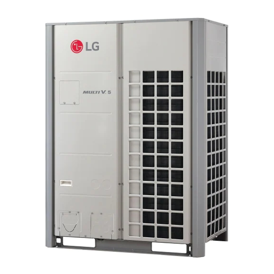
Related Manuals for LG Multi V 5 ARUV144DTE5


Summary of Contents for LG Multi V 5 ARUV144DTE5
- Page 1 Installation work must be performed in accordance with the national wiring standards by authorized personnel only. Please retain this installation manual for future reference after reading it thoroughly. Cooling Only Original instruction www.lg.com MFL67221443 Copyright © 2017 - 2019 LG Electronics Inc. All Rights Reserved. Rev.00_011719...
- Page 2 Installation TIPS FOR SAVING ENERGY • Have all electric work done by a licensed electrician according to "Electric Facility Engineering Standard" and "Interior Wire Here are some tips that will help you minimize the power consumption Regulations" and the instructions given in this manual and always when you use the air conditioner.
- Page 3 • Do not open the inlet grille of the product during operation. (Do not • Safely dispose of the packing materials. touch the electrostatic filter, if the unit is so equipped.) - Packing materials, such as nails and other metal or wooden parts, - There is risk of physical injury, electric shock, or product failure.
- Page 4 TABLE OF CONTENTS TIPS FOR SAVING ENERGY IMPORTANT SAFETY INSTRUCTIONS INSTALLATION PROCESS OUTDOOR UNITS INFORMATION ALTERNATIVE REFRIGERANT R410A SELECT THE BEST LOCATION INSTALLATION SPACE Individual Installation LIFTING METHOD INSTALLATION The location of the Anchor bolts Foundation for Installation Preparation of Piping Plumbing materials and storage methods REFRIGERANT PIPING INSTALLATION Precautions on Pipe connection / Valve operation...
- Page 5 INSTALLATION PROCESS OUTDOOR UNITS INFORMATION CAUTION Indicate clearly who will be responsible for switch setting. Determination of division work Combination Ratio(50~200%) Make connection clearly between outdoor, indoor, Preparation of contract drawings remote controller and option. Outdoor Number Connection Ratio Single outdoor units 200 % Take account of gradient Sleeve and insert work...
- Page 6 SELECT THE BEST LOCATION INSTALLATION SPACE Select space for installing outdoor unit, which will meet the following Individual Installation conditions: • No direct thermal radiation from other heat sources During the installation of the unit, consider service, inlet, and outlet acquire the minimum space as shown in the figures below.
- Page 7 LIFTING METHOD Seasonal wind and cautions in winter • Sufficient measures are required in a snow areas or severe cold areas in winter so that product can be operated well. • When carrying the suspended, unit pass the ropes under the unit and •...
- Page 8 Ⓐ The corner part must be fixed firmly. Otherwise, the support for the INSTALLATION installation may be bent. Ⓑ Get and use M10 Anchor bolt. • Install at places where it can endure the weight and vibration/noise Ⓒ Put Cushion Pad between the outdoor unit and ground support for of the outdoor unit.
- Page 9 Burrs removal Opening shutoff valve - Completely remove all burrs from the cut cross section of pipe/tube. - Put the end of the copper tube/pipe to downward direction as you Remove the cap and turn the valve counter clockwise with the remove burrs in order to avoid to let burrs drop in the tubing.
- Page 10 Plumbing materials and storage methods Nitrogen substitution method Welding, as when heating without nitrogen substitution a large Pipe must be able to obtain the specified thickness and should be amount of the oxide film is formed on the internal piping. used with low impurities.
- Page 11 REFRIGERANT PIPING 2, 3, 4 Outdoor Units INSTALLATION Outdoor units Model Liquid Pipe Gas Pipe O.D.15.88 I.D. 19.05 I.D.22.2 O.D. 28.58 I.D.34.9 I.D.15.88 I.D.15.88 I.D.28.58 I.D.28.58 I.D.12.7 I.D.9.52 I.D.19.05 ARCNN21 I.D.22.2 2 Unit I.D.31.8 I.D.34.9 I.D.22.2 O.D.19.05 I.D.41.3 I.D.38.1 O.D.34.9 I.D.12.7 Precautions on Pipe connection / Valve operation I.D.15.88...
- Page 12 PIPE CONNECTIONS BETWEEN If the diameters of the branch piping of the designated refrigerant piping differs, use a pipe cutter to cut the connecting section and INDOOR AND OUTDOOR UNIT then use an adapter for connecting different diameters to connect the piping.
- Page 13 Refrigerant piping system Remove leakage prevention cap • Remove the leakage prevention cap attached to the outdoor unit 1 Outdoor Units service valve before pipe work. • Proceed the leakage prevention cap removal as follows: - Verify whether all the pipes are locked. Y branch method - Extract remaining refrigerant or air inside using the service port.
- Page 14 WARNING Header Method ODU Capacity Slave3 Slave2 Master ≥ Slave 1 ≥Slave 2 ≥Slave 3 Ⓐ : Outdoor Unit Slave1 Increased Pipe Diameter(table 2) Master 10 m or Ⓑ : Header less - When pipe length is 90 m [295 ft] or more from ODU to 1st Ⓒ...
- Page 15 WARNING Pipes between outdoor units are 2 m [6.6 ft] or longer • In case of pipe diameter B connected after first branch is bigger Oil Trap than the main pipe diameter A, B should be of the same size 0.2 m [0.66 ft] 2 m [6.6 ft] or less with A.
- Page 16 Branch pipe Fitting (Example 2) Y branch Ⓐ To Outdoor Unit Oil Trap Ⓑ To Branch Piping or Indoor Unit ≤ 2 m [6.6 ft] Toward indoor unit ≥ 2 m [6.6 ft] CAUTION Y-branches between the outside units must be installed horizontally.
- Page 17 • Header should be insulated with the insulator in each kit. Header [Unit:mm(inch)] Models Gas pipe Liquid pipe Insulate the header using the insulation material attached to the 360(14-5/32) branch pipe kit ID9.52(3/8) 120(4-23/32) ID12.7 as shown in the figure. ID6.35(1/4) ID9.52(3/8) ID12.7...
- Page 18 Distribution Method Horizontal Distribution Slave Master Slave 3rd main pipe distribution Master Slave Master Main pipe Distribution Main pipe Distribution Vertical Distribution - Ensure that the branch pipes are attached vertically. Slave Master CAUTION Slave Master Leak Test and Vacuum drying The others Leak test Leak test should be made by pressurizing nitrogen gas to 3.8 MPa(38.7...
- Page 19 WARNING WARNING Use a vacuum pump or Inert(nitrogen) gas when doing leakage test Use a vacuum pump or Inert(nitrogen) gas when doing leakage test or air purge. Do not compress air or Oxygen and do not use or air purge. Do not compress air or Oxygen and do not use Flammable gases.
- Page 20 Thermal insulation of refrigerant piping The amount of Refrigerant The calculation of the additional charge should take into account the Be sure to give insulation work to refrigerant piping by covering liquid length of pipe and CF(correction Factor) value of indoor unit. pipe and gas pipe separately with enough thickness heat-resistant polyethylene, so that no gap is observed in the joint between indoor unit and insulating material, and insulating materials themselves.
- Page 21 Penetrations ELECTRICAL WIRING Inner wall (concealed) Outer wall Outer wall (exposed) Caution - Follow ordinance of your governmental organization for technical standard related to electrical equipment, wiring regulations and guidance of each electric power company. WARNING Floor (fireproofing) Penetrating portion on fire Roof pipe shaft limit and boundary wall Be sure to have authorized electrical engineers do the electric...
- Page 22 Master Slave Master Slave 1 Slave 2 Indoor Indoor Indoor Indoor Unit Unit Unit Unit Remote Remote Remote Remote control control control control Master Slave 1 Slave 2 Master Slave Indoor Indoor Indoor Indoor Unit Unit Unit Unit Remote Remote Remote Remote control...
- Page 23 Control box and connecting position of wiring Communication and Power Cables - Remove all of the screws at front panel and remove the panel by Communication cable pulling it forward. - Types : shielded wires or unshielded wires - Connect communication cable between main and sub outdoor unit - Cross section : 1.0 ~ 1.5 mm (1.55 ×...
- Page 24 Wiring of main power supply and equipment Field Wiring capacity 220-240V - Use a separate power supply for the Outdoor Unit and Indoor Unit. Example Connection of Communication Cable - Bear in mind ambient conditions (ambient temperature,direct sunlight, rain water,etc.) when proceeding with the wiring and 1 Outdoor Unit-3 Ø, 220-240 V connections.
- Page 25 2 Outdoor Units-3 Ø, 220-240 V Between Indoor and Master Outdoor unit When the power source is connected In series between the units. Master SODU. B SODU. A IDU. B IDU. A CEN. B CEN. A DRY1 DRY2 Outdoor Unit Power supply 3 Phase 3 Wires 50 Hz 220-240 V...
- Page 26 460V NOTE Example Connection of Communication Cable - Field wiring diagram is to be used as a guidelineonly. Wiring 1 Outdoor Unit-3 Ø, 460 V should comply with applicable local and national codes - ELCB must have function to prevent electrical short and over Power supply current at the same time .
- Page 27 When the power source is supplied to Each outdoor unit individually. 3 Outdoor Units-3 Ø, 460 V When the power source is connected In series between the units. Power supply 3 Phase 3 Wires 60Hz 460V [Master] [Slave] Power supply (Main Switch) R(L1) S(L2) T(L3) R(L1) S(L2) T(L3)
- Page 28 Between Indoor and Master Outdoor unit Front Side Main power terminal block Master SODU. B SODU. A IDU. B IDU. A CEN. B CEN. A DRY1 DRY2 Outdoor Unit Ground wire 3(A) 4(B) 3(A) 4(B) 3(A) 4(B) 3(A) 4(B) When connecting Communication wires / Ground wire from front guide panel...
- Page 29 Communication/Ground Quick control Setting Main power line In the factory setting, main PCB DIP switch setting is all “OFF”. wire connection connection - Check and make sure that all the indoor unit model name are ARNU******4. - Change the main PCB DIP switch No. 3 “OFF → ON” like below picture.
- Page 30 Automatic Addressing The Procedure of Automatic Addressing The address of indoor units would be set by Automatic Power On Addressing - Wait for 3 minutes after supplying power. Waiting 3 minutes (Master and Slave outdoor units, indoor units) - Press RED button of the outdoor units for 5 seconds. (SW01C) Press RED Button for 5 sec.
- Page 31 High Static Pressure Compensation mode Optional Mode Selection Function Selection Option Selection Remarks Display Optional This function secures the air flow rate of ODU, in case static pressure Content Display (◎) Content Default (◀, ▶ ’ ◎) (◀, ▶ ’ ◎) has been applied like using duct at fan discharge of ODU.
- Page 32 Time Settings Setting Step Judgment Time(Hr) Operation Time(Hr) Condensing Evaporating Purpose Mode temperature temperature Heat Cool variation variation 10.5 +2 °C -3 °C op1 Increase capacity Increase capacity (35.6 °F) (37.4 °F) 10.5 Decrease power +2 °C -1.5 °C Increase capacity consumption (35.6 °F) (-34.7 °F)
- Page 33 Auto Dust Removal Mode Function setting Setting Inverter (Hz) The ability to set reverse run outdoor fan to remove dust, heat exchanger. Mode setting method 143 Hz 135 Hz Master unit PCB DIP switch on : No.5 128 Hz 120 Hz Select the mode using ‘▶’, ‘◀’...
- Page 34 SLC (Smart Load Control) Central Control Connection at Indoor Unit side Function for set the variable target pressure which for the high Mode setting method efficiency and comport operation depend on ODU load. Master unit PCB DIP switch on : No.5 Mode setting method Master unit PCB DIP switch on : No.5 Select the mode using ‘▶’, ‘◀’...
- Page 35 Power Consumption Display on wired remote controller Mode setting method Master unit PCB DIP switch on : No.5 Select the mode using ‘▶’, ‘◀’ Button : “Func” Push the ‘●’ button Select the Function using ‘▶’, ‘◀’ Button : “Fn21” Push the ‘●’ button Select the Option using ‘▶’, ‘◀’...
- Page 36 Self-Diagnosis Function Error Indicator - This function indicates types of failure in self-diagnosis and occurrence of failure for air condition. - Error mark is displayed on display window of indoor units and wired remote controller, and 7-segment LED of outdoor unit control board as shown in the table.
- Page 37 Display Title Cause of Error The first start failure by Outdoor Unit Inverter Compressor Outdoor Unit Inverter Compressor Start Failure abnormality or Compressor locked Outdoor Unit Inverter Compressor Over Current Outdoor Unit Inverter Compressor Fault OR Drive Fault Outdoor Unit Inverter Compressor1 High Outdoor Unit Inverter Compressor1 High Discharge Temperature Discharge Temperature Outdoor Unit Inverter Compressor2 High...
- Page 38 Display Title Cause of Error Outdoor Unit Fan DC Link Low Voltage Error Outdoor Unit Fan DC Link Input Voltage is under 50V Outdoor Unit Liquid pipe Temperature Sensor Error Liquid pipe temperature sensor of Outdoor Unit is open or short Outdoor Unit Subcooling Inlet Temperature Outdoor Unit Subcooling Inlet Temperature Sensor Error Sensor Error...
- Page 39 CAUTION FOR REFRIGERANT LEAK Calculate refrigerant concentration Total amount of refrigerant The installer and system specialist shall secure safety against leakage system [kg(lbs)] according to local regulations or standards. = Maximum concentration limit The following standards may be applicable if local regulations are not Volume of smallest room [kg/m (lbs/ft...
- Page 40 INSTALLATION GUIDE AT THE Model Designation SEASIDE Product information • Product Name : Air conditioner CAUTION • Model Name : • Air conditioners should not be installed in areas where corrosive gases, such as acid or alkaline gas, are produced. Product Sales Name Model Factory Name ARUx***yTE5 series...