Honeywell Lyric Programming Manual
Hide thumbs
Also See for Lyric:
- User reference manual (84 pages) ,
- User quick manual (32 pages) ,
- Quick user manual (17 pages)

Related Manuals for Honeywell Lyric


Summary of Contents for Honeywell Lyric
- Page 1 Lyric Programming Guide Controller Ref: LCP500-L/LCP500-LC 800-18077V1 11/15 Rev A...
- Page 2 The security system is not designed for use with any device that may be attached to the system's control or other communicating bus if Honeywell has not approved such device for use with the system. Use of any such unauthorized device may cause damage or compromise the performance of the security system and affect the validity of the end user’s Honeywell...
-
Page 3: Table Of Contents
RF Transmitter Loop Numbers Diagram ............................40 Programming Default Values .................................. 41 Specifications ....................................... 43 Lyric Summary of Connections Diagram ............................47 Refer to the Lyric Controller Installation and Reference Guide p/n 800-18076 or later for detailed information on programming the system. - 3 -... -
Page 4: Mechanics Of Programming
Lyric Controller Programming Guide Mechanics of Programming Navigation Keys Navigating through the screens is accomplished by lightly touching the icons or menu items on the touch- screen. Once activated, the control advances to the next screen. Selecting the “Home” (cancel) key or the “... -
Page 5: Security Screen
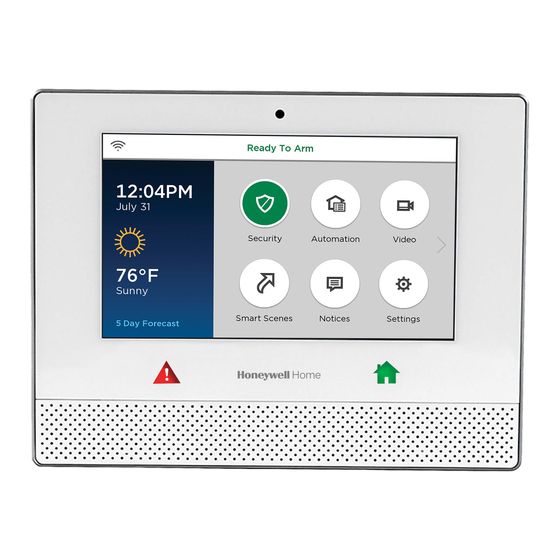
Lyric Controller Programming Guide Mechanics of Programming (Continued) Security Screen System Status is displayed at the top of each screen and the time and date are displayed at the bottom of the Security Screen. The Security Screen displays the system status and selection “icons” and “tabs”. -
Page 6: General Programming Information
If the Controller has been enrolled proceed to step 7. 6. If programming the Lyric locally, program the following fields by selecting the field and entering the required information on the keyboard. The User Name and Customer Account Number are required in order... -
Page 7: Programming The Data Fields
Lyric Controller Programming Guide Programming the Data Fields Select each desired programming option, and then select the required entry. The system beeps each time a selection is made. The system will toggle or scroll through the options or display a new screen as applicable. -
Page 8: Data Fields
Lyric Controller Programming Guide DATA FIELDS Change Installer Code Programmed Programming Field Function and Action Default 1. The current four-digit Installer Code is displayed on the left side Installer Code 4112 of the screen. Select “Clear”. 2. Enter a new four-digit Installer Code on the displayed keypad. -
Page 9: Program Date Time
Lyric Controller Programming Guide Program System Type (Continued) Programmed Programming Field Function and Action Default Enable or disable Zone Bypass Event Logging Enabled Events - Log Bypass The system toggles between “Disabled” and “Enabled”. Enable or disable Open/Close Event Logging... -
Page 10: Program Communicator
Cellular Fault Time, Cellular Rollover, Cellular 24 Hour Test fields can be viewed but are not programmable locally on the Lyric Controller. The options for those fields are shown for reference only. Only the Communications Path, DHCP and IP Address fields can be programmed locally on the Lyric Controller. - Page 11 Lyric Controller Programming Guide Program Communicator (Continued) Programmed Programming Field Function and Action Default Remote Acc. Comm. Enables or disables user remote access via internet and/or Cellular. Disabled Options: Disabled Enabled Multi Mode Comm. Enables or disables Multi Mode feature.
-
Page 12: Program Zones
Lyric Controller Programming Guide Program Zones The Lyric supports both Honeywell 5800 Series and SiX™ Series Bi-Directional sensors. The steps required to enroll these sensors differ. It should be noted that once a SiX™ Series sensor has been enrolled in the panel it must be deleted before it can be enrolled in a different panel. - Page 13 (Continued) 4. The system returns to the Zone Programming Screen and the device’s battery level and signal strength is displayed on the Lyric control. Activate the device to confirm the enrollment. NOTE: If a duplicate serial number is entered, the system will emit a single long beep and a confirmation screen will be displayed.
- Page 14 Lyric Controller Programming Guide Program Zones (Continued) Response Type The system displays the specific options, which are dependent upon the Device Type ˅ that was selected for the zone. Use the down “ ” arrow to scroll to the next page of ˄...
-
Page 15: Batch Learning Enrollment (Six™ Series Devices Only)
Batch Learning Enrollment (SiX™ Series Devices only) The Lyric Controller is capable of learning multiple SiX Series devices via the Batch (RF) Learning Mode. The system will assign each wireless device enrolled via the Batch Learning mode to the next available zone. -
Page 16: Program Keys
Program Keys The Lyric Controller features 32 Wireless Key (RF Key Fob) Zones that allow it to support a combination of one, two, four, six and eight button devices. It should be noted that once a SiX™ Series wireless key (key fob) has been enrolled in the panel it must be deleted before it can be enrolled in a different panel. -
Page 17: Deleting Wireless Zones Or Keys
After entering Master User Programming Mode select the “Advanced” icon. Follow the steps below to update the SiX™ Series Sensor or Key Fob firmware. Programming Field Function and Action Update Sensor Select “Start” to initiate Firmware Update and follow the instructions on the Lyric, Firmware as applicable. Select “Stop” when Firmware Update. Update Keyfob 3. -
Page 18: Program Reporter
Lyric Controller Programming Guide Program Reporter Programmed Programming Field Function and Action Default ˅ Report Selection Not Applicable Enable or disable Reporting of Specific Events. Use the down “ ” ˄ arrow to scroll to the next page of options. Use the “... - Page 19 Lyric Controller Programming Guide Program Reporter (Continued) Programmed Programming Field Function and Action Default Enable or disable reports to the Central Station when the system Low Battery Enabled detects a Low Battery condition. The system toggles between “Disabled” and “Enabled”.
-
Page 20: Program Sounder
Lyric Controller Programming Guide Program Sounder Programmed Programming Field Function and Action Default Burglary Alarm Reduces the full burglary alarm sound for testing. The system Sound toggles between the available options. Options: Yes (Full volume) No (Test volume – installer mode) - Page 21 Lyric Controller Programming Guide Program System Settings Programmed Programming Field Function and Action Default Entry Delay 1 Select an Entry Delay time in seconds. The system will wait the 30 Seconds selected time before sounding alarm upon entering, if system has not been disarmed.
- Page 22 Lyric Controller Programming Guide Program System Settings Restart Exit Time Disable or enable Restart Exit Time Mode after the system has been armed and the Exit Delay is counting down. If enabled, the Exit Delay time can be restarted by selecting the “Restart” icon and entering the User Code (if quick arming is disabled) or by selecting the Restart icon (if quick arming is enabled).
-
Page 23: Program Z-Wave
Lyric Controller Programming Guide Program System Settings (Continued) Programmed Programming Field Function and Action Default Select “Cross Zone Delay”. The System toggles between the [(A) – (D)] Cross None following: Zone Delay None 30 Seconds 1 Minute 90 Seconds 2 Minutes... -
Page 24: Program Rf Keypad
Lyric Controller Programming Guide Program RF Keypad The Lyric supports the installation of up to eight SiX™ Series RF keypads. The Keypad should be setup in accordance with the documentation provided with the keypad prior to beginning the enrollment process. A Zone Descriptor should be assigned to each enrolled Keypad to ensure that Zones can be easily identified. -
Page 25: Communication Diagnostics
Choose from the following options (depending upon the Communication Module that is installed): Configure WiFi – Provides access to the options for connecting the Lyric Controller panel to a WiFi Network WiFi Information – Displays IP information if the WiFi Communication Path is enabled. - Page 26 Lyric Controller Programming Guide Communications Diagnostics (Continued) WiFi Protected Set up (WPS) NOTE: For WPS operation, press the WPS button on the access point first. Then press the WPS button within 2 minutes Select “WPS”, the system displays “Please Stand-by for WPS Operation…”.
- Page 27 * = Number of the director being tested is displayed Send Any If both WiFi and Cellular communication paths are enabled and the Lyric Controller is registered, a Test alarm is sent over WiFi path. If that is not successful, it sends the alarm over Cellular path.
-
Page 28: Registering The Lyric Control
When choosing a suitable mounting location, check the communications module’s signal strength to ensure proper operation. For most installations, using the module’s internal antenna, mounting the Lyric controller as high as practical, and avoiding large metal components provides adequate signal strength for proper operation. -
Page 29: Testing The System
Lyric Controller Programming Guide Testing the System After installation is completed, the security system should be carefully tested, as follows: Step Action With the system in the disarmed state, check that all zones are intact. If the “Home” button is not lit, select the Zones icon to display the faulted zone(s). -
Page 30: Rebooting The System
Lyric Controller Programming Guide Testing the System (Continued) Programming Field Function and Action RF Sniffer Test NOTE: If the communicator is in the process of sending a report to the Central Station, the system will not enter the RF Sniffer Mode. Wait a few minutes and try again. -
Page 31: Zone Programming Worksheet
Lyric Controller Programming Guide Zone Programming Worksheet Fill in the required data on this worksheet, then follow the programming procedure. (The defaults for Configuration 1 are shown) See Explanation of Zone Assignment Table Headings Zone Loop Device Response Alarm Transmitter... - Page 32 Lyric Controller Programming Guide Zone Programming Worksheet (Continued) Zone Loop Device Response Alarm Transmitter Zone Chime Supervision Type Type Report Night Serial Number Descriptor - 32 -...
- Page 33 Lyric Controller Programming Guide Zone Programming Worksheet (Continued) Zone Loop Device Response Alarm Transmitter Zone Chime Supervision Type Type Report Night Serial Number Descriptor - 33 -...
- Page 34 Lyric Controller Programming Guide Zone Programming Worksheet (Continued) Zone Loop Device Response Alarm Transmitter Zone Chime Supervision Type Type Report Night Serial Number Descriptor - 34 -...
-
Page 35: Explanation Of Zone Assignment Table Headings
Lyric Controller Programming Guide Zone Programming Worksheet (Continued) Zone Loop Device Response Alarm Transmitter Zone Chime Supervision Type Type Report Night Serial Number Descriptor - 35 -... - Page 36 Lyric Controller Programming Guide Zone Programming Worksheet (Continued) Zone Loop Device Response Alarm Transmitter Zone Chime Supervision Type Type Report Night Serial Number Descriptor Not Used Standard Supervised Main Not Used Standard Supervised Main Not Used Standard Supervised Main Not Used...
- Page 37 Lyric Controller Programming Guide Zone Programming Worksheet (Continued) Zone Loop Device Response Alarm Transmitter Zone Chime Supervision Type Type Report Night Serial Number Descriptor Key Fob Disabled Button Response Not Used Disabled Button Not Used Disabled Button Not Used Disabled...
- Page 38 Lyric Controller Programming Guide Zone Programming Worksheet (Continued) Zone Loop Device Response Alarm Transmitter Zone Chime Supervision Type Type Report Night Serial Number Descriptor Not Used Disabled Button Not Used Disabled Button Temp. Monitor Disabled High Temp Temp. Monitor Disabled Low Temp Temp.
- Page 39 Lyric Controller Programming Guide Zone Programming Worksheet (Continued) Zone Loop Device Response Alarm Transmitter Zone Chime Supervision Type Type Report Night Serial Number Descriptor Panic Medical Not Used Disabled Trigger Local Panic Local Disabled Alarm Trigger 24 Hour Panic Police...
-
Page 40: Rf Transmitter Loop Numbers Diagram
Lyric Controller Programming Guide RF Transmitter Loop Numbers NOTES: (1) The 5806W3 smoke detector must be used in SIA applications. (2) Button type devices send only fault and low battery signals; no restore or check-in signals. Supervised RF devices send periodic check-in signals, faults, restore and low battery signals. -
Page 41: Programming Default Values
Lyric Controller Programming Guide Programming Default Values Program Function Configuration 1 Configuration 2 Configuration 3 Configuration 4 Installer Code 4112 4112 4112 4112 System Type RF Jam Log RF Jam Log RF Jam Log RF Jam RF Jam Log RF House Code... - Page 42 Lyric Controller Programming Guide Programming Default Values Program Function Configuration 1 Configuration 2 Configuration 3 Configuration 4 Test Enabled Enabled Enabled Enabled Test Restore Enabled Enabled Enabled Enabled Bypass Enabled Enabled Enabled Enabled Bypass Restore Enabled Enabled Enabled Enabled AC Loss...
-
Page 43: Specifications
Lyric Controller Programming Guide Specifications Lyric Controller Series Residential Burglar and Fire Alarm Control Panel Physical: Dimensions: 8.5” (216mm) W x 6.65” (169mm) H x 1.3” (33mm) D Electrical: Voltage Input: 110VAC, 60 Hz/9 Vdc from plug-in 2.7A power supply Rechargeable Backup Battery: Nickel-metal hydride battery pack rated at 7.2 Vdc... - Page 44 Lyric Controller Programming Guide – Notes – - 44 -...
- Page 45 Lyric Controller Programming Guide – Notes – - 45 -...
- Page 46 Lyric Controller Programming Guide – Notes – - 46 -...
-
Page 47: Lyric Summary Of Connections Diagram
Lyric Controller Programming Guide Lyric Residential Burglar and Fire Alarm Control Panel Summary of Connections - 47 -... - Page 48 2 Corporate Center Drive, Suite 100 P.O. Box 9040, Melville, NY 11747 Copyright © 2015 Honeywell International Inc. www.honeywell.com/security Ê800-18077V1gŠ 800-18077V1 11/15 Rev A...