D-Link DGS-1210 Series User Manual
Metro ethernet managed switch
Hide thumbs
Also See for DGS-1210 Series:
- Manual (175 pages) ,
- User manual (159 pages) ,
- Reference manual (107 pages)
Advertisement
1 Product Introduction
1
Product Introduction
Switch Description
Front Panel Description
LED Indicators
Rear Panel Description
Side Panel Description
Connecting the DPS-200A/500A/500DC to the RPS Port (for DGS-1210-
10/12TS/20/28X/28XS/52/ME only)
Installing the RPS into the Rack-mount Chassis (for DGS-1210-10/12TS/20/28X/28XS/52/ME only)
Switch Description
The DGS-1210/ME Metro Ethernet Switch is equipped with Copper ports (10/100/1000Mbps) and SFP
ports (1000Mbps) that can be used to attach various networking devices to the network like Computers,
Notebooks, Print Servers, Network Attached Storage devices, IP Cameras, VoIP PBX devices, and other
Switches. The Small Form Factor Portable (SFP) ports can be used together with fiber-optical transceivers in
order to connect various other networking devices, using a fiber-optic connection, to the network at Gigabit
Ethernet speeds over great distances.
This DGS-1210/ME Metro Ethernet Switch provides unsurpassed performance, fault tolerance, scalability,
robust security, standard-based interoperability and impressive technology to future-proof departmental and
enterprise network deployments.
It allows IGMP Snooping and Authentication, QoS, Bandwidth Control, ACL and many security functions. It
can be managed by Web UI, or commands via Telnet.
The DGS-1210/ME Metro Ethernet Switches have different port configuration (10/100/1000Base-T or SFP
ports) that may be used in to uplink various network devices to the Switch, including PCs, hubs and other
switches to provide a gigabit Ethernet uplink in full-duplex mode. The SFP (Small Form Factor Portable)
ports are used with fiber-optical transceiver cabling in order to uplink various other networking devices for a
gigabit link that may span great distances.
Front Panel Description
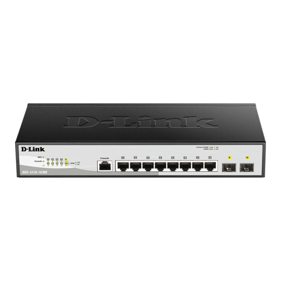
The front panel of the DGS-1210-10/ME switch consists out of the following:
• 8 10/100/1000Mbps Copper Ports
• 2 1000Mbps SFP ports
• One RJ-45 Console Port
• LEDs for Power, Console, RPS, Link/Act for port 1 ~ 10
DGS-1210 series Metro Ethernet Managed Switch User Manual
Figure 1.1 – DGS-1210-10/ME Front Panel
CAUTION: The MiniGBIC ports should use UL listed
Optical Transceiver product, Rated Laser Class I. 3.3Vdc.
PRÉCAUTION: Les ports Mini GBIC doivent utiliser la
liste UL. Produit émetteur-récepteur optique, classe laser
I. 3.3Vdc.
2
Advertisement
Table of Contents

Related Manuals for D-Link DGS-1210 Series


Summary of Contents for D-Link DGS-1210 Series
- Page 1 1 Product Introduction DGS-1210 series Metro Ethernet Managed Switch User Manual Product Introduction Switch Description Front Panel Description LED Indicators Rear Panel Description Side Panel Description Connecting the DPS-200A/500A/500DC to the RPS Port (for DGS-1210- ...
- Page 2 1 Product Introduction DGS-1210 series Metro Ethernet Managed Switch User Manual The front panel of the DGS-1210-10P/ME switch consists out of the following: • 8 10/100/1000Mbps Copper Ports • 2 1000Mbps SFP ports • One RJ-45 Console Port • LEDs for Power, PoE Max, Console, Link/Act for port 1 ~ 10 •...
- Page 3 1 Product Introduction DGS-1210 series Metro Ethernet Managed Switch User Manual Figure 1.4 – DGS-1210-20/ME Front Panel CAUTION: The MiniGBIC ports should use UL listed Optical Transceiver product, Rated Laser Class I. 3.3Vdc. PRÉCAUTION: Les ports Mini GBIC doivent utiliser la liste UL.
- Page 4 1 Product Introduction DGS-1210 series Metro Ethernet Managed Switch User Manual NOTE: The power budget is 193 Watts for DGS-1210-28P/ME. The front panel of the DGS-1210-28MP/ME switch consists out of the following: • 24 10/100/1000Mbps Copper Ports • 4 1000Mbps SFP port •...
- Page 5 1 Product Introduction DGS-1210 series Metro Ethernet Managed Switch User Manual CAUTION: The MiniGBIC ports should use UL listed Optical Transceiver product, Rated Laser Class I. 3.3Vdc. PRÉCAUTION: Les ports Mini GBIC doivent utiliser la liste UL. Produit émetteur-récepteur optique, classe laser I.
-
Page 6: Led Indicators
1 Product Introduction DGS-1210 series Metro Ethernet Managed Switch User Manual • Mode: By pressing the Mode button, the Port LED will switch between Link/Act and PoE modes Figure 1.12 – DGS-1210-52MP/ME Front Panel CAUTION: The MiniGBIC ports should use UL listed Optical Transceiver product, Rated Laser Class I. - Page 7 1 Product Introduction DGS-1210 series Metro Ethernet Managed Switch User Manual Solid Console on. Light Console Green Blinking POST is in progress. Light Console off. Fan Error (for DGS-1210-28P/ME, Solid The fan has runtime failure and 28MP/ME, 28X/ME, 28XS/ME, light is brought offline.
-
Page 8: Rear Panel Description
1 Product Introduction DGS-1210 series Metro Ethernet Managed Switch User Manual When there is a secure Solid 100Mbps connection at the port. Light (For DGS-1210-28XS/ME only) Amber When there is reception or Blinking transmission occurring at the Amber port. (For DGS-1210-28XS/ME... - Page 9 1 Product Introduction DGS-1210 series Metro Ethernet Managed Switch User Manual DGS-1210-20/ME Figure 1.18- DGS-1210-20/ME Rear Panel DGS-1210-28/ME Figure 1.19-DGS-1210-28/ME Rear Panel DGS-1210-28P/ME Figure 1.20 - DGS-1210-28P/ME Rear Panel DGS-1210-28MP/ME Figure 1.21 -DGS-1210-28MP/ME Rear Panel DGS-1210-28X/ME Figure 1.22- DGS-1210-28X/ME Rear Panel DGS-1210-28XS/ME Figure 1.23-...
-
Page 10: Side Panel Description
1 Product Introduction DGS-1210 series Metro Ethernet Managed Switch User Manual DGS-1210-52P/ME Figure 1.25 - DGS-1210-52P/ME Rear Panel DGS-1210-52MP/ME Figure 1.26 - DGS-1210-52MP/ME Rear Panel DGS-1210-52MPP/ME Figure 1.27 - DGS-1210-52MPP/ME Rear Panel Side Panel Description The left- and right-hand panels of the Switch have heat vents to dissipate heat. Do not block these openings, and leave at least 6 inches of space at the rear and sides of the Switch for proper ventilation. - Page 11 1 Product Introduction DGS-1210 series Metro Ethernet Managed Switch User Manual Figure 1.29 - Inserting the SFP modules into the Switch Figure 1.30 - Installing the SFP Module The Switch is equipped with SFP ports, which are to be used with fiber-optical transceiver cabling in order to uplink various other networking devices for a gigabit link that may span great distances.
-
Page 12: Installing The Rps Into A Rack-Mount Chassis (For Dgs-1210-10/12Ts/20/28/28X/28Xs/52/Me Only)
1 Product Introduction DGS-1210 series Metro Ethernet Managed Switch User Manual The following section explains how to connect the DPS-200A/500A/500DC to the Switch. • Disconnect the Switch from the main AC power source. • Insert the 14-pin end of the DPS-CB150-2PS into the DPS-200A/500A/500DC and the 2-pin end into the receptacle of the RPS port on the Switch.