Table of Contents
Advertisement
Quick Links
Advertisement
Chapters
Table of Contents

Related Manuals for Husqvarna 241R


Summary of Contents for Husqvarna 241R
- Page 1 Workshop manual 241R 241RJ English...
- Page 2 Starter Workshop Manual Brushcutter, Trimmer Model 241R, 241RJ Contents General recommendations ______________________ 2 1. Starter ___________________________________ 3 2. Electrical system ___________________________ 7 3. Fuel system ______________________________ 13 4. Centrifugal clutch __________________________ 29 5. Angle gear _______________________________ 35 6. Cylinder and piston ________________________ 39 7.
- Page 3 Operator’s Manual. The assembly of other equipment or accessories or spare parts not approved by Husqvarna can result in the failure to meet these safety demands and that the person carrying out assembly bears responsibility for this.
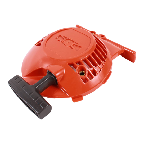
- Page 4 Starter Starter Contents Dismantling ___________________________________ 4 Assembly _____________________________________ 5 Replacing the drive dogs _________________________ 6...
- Page 5 Starter WARNING! Protective glasses should be worn when working on the starter to avoid injury to the eyes if, for some reason, the return spring should fl y out. Dismantling Demontering Remove the starter from the engine. Remove the 4 screws and carefully swing down the protective plate so far that the starter can be lifted out.
- Page 6 Starter Assembly Assembly Clean the component parts and assemble Clean component parts before in the reverse order as set out for dismant- assembling. ling. Replace the return spring/starter pulley and starter cord, if necessary. NOTE! The return spring and starter pulley are supplied pre-assembled and are fi...
- Page 7 Starter Fit the starter on the engine body. 1. Check that the rubber bushings (A) are in position in the starter housing. 2. Insert the small tab (B) on the periphe- ry of the starter under the carburettor cover and swing the starter in against the engine body.
- Page 8 Electrical system Electrical system Contents Checking the ignition spark ___________________10 Dismantling _______________________________12 Assembly _________________________________14...
- Page 9 Electrical system The engine is equipped with an electronic ignition system completely without moving parts. Conse- quently, a faulty component cannot be repaired, but must be replaced by a new component. The spark in an electronic ignition system has a very short burn time and can therefore be interpre- ted as weak and can be diffi...
- Page 10 Electrical system When there is still no ignition spark, dismantle the short-circuit cable from the stop switch. Remove the connector by prying it up out of the throttle with a knife. If the plug now sparks, the fault is either in the stop switch or the short-circuit cable.
- Page 11 Electrical system Still no spark? Still no spark? Check other cables and connections for Check other cables and connections. poor contacts (dirt, corrosion, cable brea- kage and damaged insulation). Make sure that the cables are correctly drawn and lie in the cable grooves. Do not forget to check the cables in the throttle too.
- Page 12 Electrical system Dismantle the guard plate under the en- gine body (2 remaining screws). Lift out the ignition lead and short-circuit cables from their guides. Remove the 3 screws (E) and swing the engine body to one side so the clutch becomes accessible.
- Page 13 Electrical system Remove the fl ywheel. Dismantle the fl ywheel from the crankcase using the puller no. 502 51 49-01. Gently knock the puller screw with a hammer, if the fl ywheel sits tightly on the crankshaft. 502 51 49-01 Assembly Check that the cast key in the fl...
-
Page 14: Table Of Contents
Fuel system Fuel system Contents Air fi lter __________________________________14 Tank venting ______________________________15 Fuel fi lter _________________________________15 Fuel pump ________________________________16 Carburettor _______________________________16 Throttle handle model RJ ___________________ 23 Throttle handle model R ____________________ 24 Start throttle speed ________________________ 25 Carburettor settings________________________ 25... -
Page 15: Air Fi Lter
Make sure that the air fi lter is free of cleaning agent before it is impregnated with air fi lter oil. TIP! Use Husqvarna’s cleaning agent Active Cleaning no. 505 69 85-70. 505 69 85-70 Impregnate the fi lter with air fi lter oil. -
Page 16: Fuel Fi Lter
Fuel system Tank venting Tank venting Tank venting takes place through the fuel Check that the tank venting valve works cap and needs to be functional for the correctly. engine to work. • Remove the starter. • Remove the air fi lter cover and dismantle the cylinder cover. -
Page 17: Fuel Pump
Fuel system Fuel pump Fuel pump The fuel pump facilitates cold starts. The fuel pump has the task of facilitating the start of the engine when cold. The pump fi lls the carburettor with fuel before attempting to start the engine. This also prevents vapour bubbles from blocking the narrow fuel channels. - Page 18 Fuel system The carburettor’s design The carburettor’s design The carburettor can be divided into three The carburettor can be divided into three different functional units: the metering unit, different functional units: the metering the blending unit, and the pump unit. unit, the blending unit, and the pump unit.
- Page 19 Fuel system Dismantling the carburettor Dismantling the carburettor Remove the control diaphragm and check Carefully remove the control diaphragm for damage. (A) and gasket (B). Replace if required. Check the diaphragm for holes and wear on the pin (C). Replace the diaphragm if required. Pressure test the metering unit.
- Page 20 Fuel system Check the needle valve and the lever arm Check the needle valve for damage on the for damage or wear. tip and in the lever arm groove. Replace damaged components with new Check the lever arm for damage to the ones.
- Page 21 Fuel system Press out the main jet (A) with a suitable Dismantle the main jet (A) and the plug (B). punch. Remove the plug (B). Carefully drill a small hole (Ø 2 mm) in the plug and pry it up with a pointed object. Remove the valves and dampers.
- Page 22 Fuel system • Mount the valves and dampers. Replace the fuel screen if it is damaged or cannot be cleaned. Zama C1Q-EL36 Place the pump diaphragm closest to the carburettor housing. Then the gasket and cover and the other components in reverse order of removal.
- Page 23 Fuel system Fit the jet needles and adjust their setting. H = 1.2 revolution open L = 1.2 revolution open NOTE! The H-needle is a little shorter than the L-needle. Press the stop plugs (A) into position using tool 540 06 82-01. Check that the O-ring is correctly seated and that the stop plug’s grooves fi...
-
Page 24: Throttle Handle Model Rj
Fuel system Inspect the heat guard’s (A) contact sur- faces against the carburettor and cylinder, respectively, checking for cracking wear which may cause leaks. Inspect the distance piece (B) for crack- ing wear or other damage that may cause leaks, which may in turn cause irregular idling and starting problems. -
Page 25: Throttle Handle Model R
Fuel system Split the shaft. Loosen the screw (A) and pull away the front part of the two-piece shaft. Separate both halves of the throttle. Separate the throttle halves as described Slide the front vibration damper (7) off of above. the shaft. -
Page 26: Start Throttle Speed
Fuel system Start throttle speed The start throttle speed can be adjusted using screw (G) Proceed as follows: 1. Start the engine and let it idle. 2. Press down the start throttle lock (C). 3. When the start throttle speed is too low (below 4000 rpm), screw the adjuster screw (G) clockwise until the cutting equipment starts to rotate. - Page 27 Fuel system Fine adjustment after running-in After the running-in period it may be necessary to fi ne adjust the carburettor nozzles, usually to get a leaner fuel/air mix. The basic factory setting is somewhat “richer” than the optimal setting (fast idle speed is 600 - 800 rpm below recommended maximum revs) and shall be maintained for the fi...
- Page 28 Fuel system Adjustment after cleaning After complete cleaning, replacement of carburettor nozzles or complete carburettor, both basic setup and fi ne adjustment must be carried out. The basic setup is: H = 1.2 revs open L = 1.2 revs open For the adjustment to be correct, it must be done under load and with warmed-up en- gine.
- Page 29 Fuel system Idling speed T-screw Correctly adjusted carburettor Let the engine idle for about 30 seconds or until the speed has A correctly adjusted carburettor means that the engine accele- stabilised. Adjust the adjuster screw for the idle speed until the rates without hesitation and it four-strokes a little at full throttle.
- Page 30 Centrifugal clutch Centrifugal clutch Contents Centrifugal clutch – Dismantling ________________ 30 Centrifugal clutch – Assembly __________________ 31 Clutch drum and drive axle – Dismantling _________ 31 Clutch drum and drive axle – Assembly __________ 33...
- Page 31 Centrifugal clutch The centrifugal clutch has the task of transferring the power from the engine to the cutting equipment’s drive axle. As the name implies, it works according to a centrifugal principle. This means the clutch’s friction shoes are thrown outwards towards the clutch drum at a certain engine speed.
- Page 32 Centrifugal clutch Dismantle the centrifugal clutch. Remove both screws (F) holding the cen- trifugal clutch. Lift off the clutch and both support wash- ers. 502 50 18-01 Twist apart the clutch and inspect the Twist apart the clutch. different parts with regard to wear or Inspect the different parts with regard to damage.
- Page 33 Centrifugal clutch Dismantle the connection sleeve. Remove the screws (B), (C) and (D) and lift off the connection sleeve (E) from the clutch housing. Dismantle the vibration element (F) Press the vibration element (F) together together with the clamping sleeve for pos- with the clamping sleeve out from the con- sible replacement.
- Page 34 Centrifugal clutch Check the inside diameter of the clutch Check the clutch drum for wear. drum. If it exceeds 64.0 mm it should be The diameter must not exceed 64.0 mm. If replaced. this is the case replace the clutch drum. The shaft contains a long guide for the The drive axle is guided in the shaft with drive axle.
- Page 35 Centrifugal clutch...
- Page 36 Angle gear Angle gear Contents Gear ratio __________________________________ 36 Dismantling ________________________________ 36 Assembly __________________________________ 37 Drive axle __________________________________ 37...
- Page 37 Angle gear The angle gear has two purposes: The fi rst is to gear down the engine’s high speed to better suit the lower speed a saw blade or trimmer requires to work effi ciently. Secondly, the angle gear contributes towards the operator’s working stance so that it is comfor- table and at the same time effi...
- Page 38 Angle gear Dismantle the bearings from the output Dismantle the bearings from the output and input axles. and input axles with the help of a small bearing puller. TIP! Hold the bearing puller in a vice so that it gains a better grip around the bearing. Assembly Clean all component parts and replace if damaged or worn.
- Page 39 Angle gear On models with a two-piece shaft, the On models with a two-piece shaft, the guide becomes accessible once the shaft guide becomes accessible once the shaft has been split (see chapter 3). has been split (see chapter 3). Dismantle the sleeve (A) and pull out the guide (B) by pulling the drive axle.
- Page 40 Cylinder and piston Cylinder and piston Contents Dismantling ________________________________ 40 Cleaning, inspection _________________________ 41 Analysis and actions _________________________ 41 Service tips ________________________________ 46 Wear tolerances ____________________________ 46 Assembly __________________________________ 47...
-
Page 41: Dismantling
Cylinder and piston The cylinder and the piston are two of the components exposed to most strain in the engine. They must withstand, for example, high speeds, large temperature swings and high pressure. Moreover, they must be resistant to wear. Despite these tough working conditions, major piston and cylinder failure is relatively uncommon. -
Page 42: Cleaning, Inspection
Cylinder and piston Cleaning, inspection After dismantling, clean the individual components: 1. Scrape carbon deposits from the top of the piston. 2. Scrape carbon deposits from the cylinder’s combustion chamber. 3. Scrape carbon deposits from the cylinder’s exhaust port. NOTE! Scrape carefully with not too sharp a tool so as not to damage the soft aluminium parts. - Page 43 Clean or replace the spark arrestor mesh. Blocked spark arrestor mesh in the muffl er. For the best results we recommend Husqvarna two-stroke oil or ready-mixed fuel that is specially developed for air-cooled two-stroke engines. Mixing ratio: 1:50 (2%). If Husqvarna two-stroke oil is not available another good quality two-stroke oil can be used.
- Page 44 Cylinder and piston Piston damage caused by a too high engine speed. Typical damage from too high engine speed is ruptured piston ring/piston rings, broken circlip on the gudgeon pin, faulty bearings or that the guide pin for the piston ring has become loose.
- Page 45 Cylinder and piston Foreign objects Everything other than clean air and pure fuel that enters the engine’s inlet port causes some type of abnormal wear or damage to the cylinder and piston. This type of increased wear shows on the piston’s inlet side starting at the lower edge of the piston skirt.
- Page 46 Cylinder and piston Larger, softer particles that penetrate into the engine cause damage to the piston skirt under the piston ring as the illustration shows. Action: Cause: Fit the air fi lter correctly. • Air fi lter incorrectly fi tted. Fit a new air fi...
-
Page 47: Service Tips
Cylinder and piston Service tips Defect: Action: Broken cooling fi ns, damaged threads or sheared bolts by In severe cases – replace the cylinder. the exhaust port. Repair the threads using Heli-Coil. Seizure marks in the cylinder bore (especially by the Polish the damaged area using a fi... -
Page 48: Assembly
Cylinder and piston Assembly Assembly Lubricate the gudgeon pin’s needle Lubricate the gudgeon pin’s needle bearing with a few drops of engine oil. bearing with a few drops of engine oil. Direct the arrow on the top of the piston towards the exhaust port. - Page 49 Cylinder and piston...
- Page 50 Crankshaft and crankcase Crankshaft and crankcase Contents Dismantling ________________________________ 50 Inspecting the crankshaft ______________________ 52 Assembly _________________________________ 52...
- Page 51 Crankshaft and crankcase The task of the crankshaft is to transform the reciprocating motion of the piston to rotation. This requires a stable design withstanding immense pressure and rotational and bending strain, as well as high rotational speed. In addition the connecting rod is exposed to large acceleration and retarda- tion forces as it moves between the top and bottom dead centres.
- Page 52 Crankshaft and crankcase Lift off the plastic piece that separates the Lift off the plastic piece that separates the wide fl ush channel in the crankcase. wide fl ush channel in the crankcase. Dismantle the ball-bearings from the Dismantle the ball-bearings from the crankcase halves.
- Page 53 Crankshaft and crankcase Inspecting the crankshaft Inspecting the crankshaft Inspect the large end of the connecting rod. The crankshaft cannot be reconditio- ned but must be replaced if it is worn or damaged. Inspect the large end of the connecting rod.
- Page 54 Crankshaft and crankcase Fit the sealing rings in the crankcase Fit the sealing rings in the crankcase halves. halves with the help of a suitable punch. Turn the sealing rings so the metal collar faces outwards. Fit the crankshaft, guide sleeves and Fit the crankshaft in the clutch side’s guide rail in the clutch side’s crankcase crankcase half.
- Page 55 Crankshaft and crankcase Assemble the cylinder. Assemble the cylinder. Position the cylinder base gasket. Lubricate the piston and piston rings with a few drops of oil. Use the piston ring compressor and care- fully slide the cylinder into position. Tighten the four screws, crosswise. 502 50 70-01 Assemble the remaining parts in the re- verse order as set out for dismantling.
- Page 56 List of tools Tools Contents Starter __________________________________ 56 Electrical system __________________________ 56 Fuel system ______________________________ 56 Centrifugal clutch __________________________ 56 Angle gear _______________________________ 57 Cylinder and piston ________________________ 57 Crankshaft and crankcase ___________________ 57 Workshop equipment _______________________ 57...
- Page 57 List of tools 505 69 85-70 531 00 48-63 502 50 18-01 502 51 91-01 502 50 18-01 502 51 49-01 502 71 13-01 531 00 60-76 502 71 14-01 503 80 17-01 531 03 06-23 502 51 34-02 505 38 13-08 502 50 06-01 502 50 83-01 502 50 19-01...
- Page 58 List of tools 503 97 64-01 502 50 18-01 502 50 18-01 502 51 03-01 544 13 05-01 502 52 42-01 502 50 70-01 531 03 06-23 544 13 08-01 502 50 70-01 502 71 14-01 544 13 09-01 505 69 85-70 544 13 10-01 502 50 19-01 544 34 87-01...
- Page 59 List of tools...
- Page 60 Technicel data Technical data Contents Engine __________________________________ 60 Ignition system ____________________________ 60 Carburettor ______________________________ 60 Clutch __________________________________ 60 Driving __________________________________ 60 Dimensions ______________________________ 60 Vibrations ________________________________ 60...
- Page 61 Technicel data Engine R/RJ Displacement, cm 40.3 Cylinder bore, mm 41.0 Stroke, mm 30.5 Compression ratio Max output, kW / speed, rpm 1.4 / 8400 Ignition system SEM DM digital, max speed, rpm 11600 Pre-ignition at max output, degrees Pre-ignition at idling, degrees Spark plug, NGK BPMR 7A Spark plug, electrode gap, mm...
- Page 62 115 11 96-26 2008W37...