Table of Contents
Advertisement
Quick Links
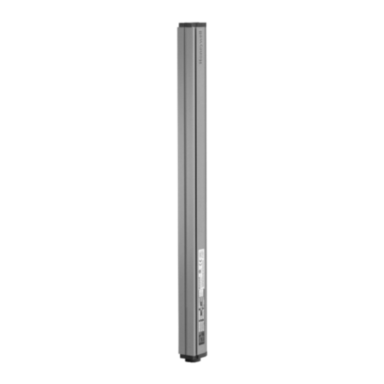
FF-SYA14, FF-SYA30 and FF-SYA60 Series
Safety Light Curtains
FF-SYA234
Multibeam Systems for Access Detection
NOTICE
PRODUCT IMPROVEME NTS ON FF-SYA SAFETY
LIGHT CURTAIN
Your FF-SYA safety light curtain has gone through some
minor product improvements, that are mechanically and
electrically fully compatible with the previous versions. In
particular, refer to chapters Scanning Ranges, Test Input
and Accessories Order Guide of the enclosed installation
manual.
IMPROPER INSTALLATION
®
Consult with US and/or European safety agencies and
their requirements when designing a machine control
C
US
link, interface and all control elements that affect safety.
Strictly adhere to all installation instructions.
Failure to comply with these instructions could
result in death or serious injury.
© 2003 Honeywell International Inc. All rights res erved.
107094-10-EN FR26 GL O 103 Printed in France
Advertisement
Table of Contents

Related Manuals for Honeywell FF-SYA234 Series


Summary of Contents for Honeywell FF-SYA234 Series
- Page 1 Strictly adhere to all installation instructions. Failure to comply with these instructions could result in death or serious injury. © 2003 Honeywell International Inc. All rights res erved. 107094-10-EN FR26 GL O 103 Printed in France...
- Page 2 Copy right, 2003 By Honey well All rights res erv ed. No part of this manual may be reproduc ed in any form or by any other means , without permis s ion from the publis hers. Revision History Reference Circulation Description Languages 107094-10...
-
Page 3: Table Of Contents
2.4.2 Resolution (FF-SYA14, FF-SYA30 and FF-SYA60 Series)..............7 2.4.3 Protection Hei g ht (FF-SYA14, FF-SYA30 and FF-SYA60 series) ............8 2.4.4 Beam spacing and number of beams (FF-SYA234 Series) ..............8 2.4.5 Response Time ..........................9 2.4.6 Scanning Ranges ..........................9 Indicators............................ - Page 4 4. ELECTRICAL CONNECTIONS.......................35 Connector Wiring for the FF-SYA GGGGG C2 light curtains..............35 Connector wiring for the FF-SYA GGGGG Q2 light curtains ..............36 Terminal strip wiring for the FF-SYA GGGGG T2 light curtains ..............36 Power Wiring (emitter and receiver terminals 1 and 2)................37 Machine Stop contacts (Receiver terminals 4 and 5)................40 4.5.1 Permanent Self-checking (Monitoring) ....................40 4.5.2 Protection of Machine Stop Contacts ....................40...
-
Page 5: Important Information
1. Important Information 1.1 Overview Thank you for purchasing this Honeywell safety product. This manual contains description, operation, installation, electrical connections, maintenance and trouble-shooting information related to the FF-SYA product. These installation instructions do not provide instructions for operating the machine on which the FF-SYA product is installed. Information about the machine operation can be found in the machine manufacturer’s operating instructions. -
Page 6: Approvals
1.5 Approvals Approvals Description Packaging, documentation and the FF-SYA Series products carry the CE mark. The EC declaration of conformity is at the back of this manual INRS “Institut National de Recherche et de Sécurité”: French notified body for the CE certification of Electrosensitive protective Equipment cCSAus The Canadian Standard Association (CSA) and the Underwriter Laboratories (UL) have been accredited as a... -
Page 7: United States Regulations Compliance
EN 954-1 Safety of Machinery - Safety related parts of control system Honeywell FF-SR Series safety control modules may be used as an interface between protective safety equipment and machine control circuitry. The following safety control modules are particularly recommended: •... -
Page 8: Description And Operation
The FF-SYA60 Series light curtains are designed for presence detection in dangerous areas where legs or a body need to be detected. The FF-SYA234 Series multibeam systems are used for access detection in dangerous areas where a body needs to be detected. - Page 9 Figure 2-1 Point-of-operation Guarding (use FF-SYA14 and FF-SYA30 only) Operator enters danger zone Operator enters danger zone under the light curtain above the light curtain Point-of-operation is defined as that area where a machine performs work (such as cutting, shaping, boring, or forming) on a material.
-
Page 10: Approval And Rating Plates
Date Date code (month/year) sensitivity” in USA standards) Beam spacing Sealing Supply Voltage (power consumption) Loads specifications (max. impedance and min. turn-on voltage) Response time Honeywell website for Sales and Service Service 107094-10-EN FR26 GL O 103 Printed in France... -
Page 11: Operation
Approvals Description Packaging, documentation and the FF-SYA Series products carry the CE mark. The EC declaration of conformity is at the back of this manual. INRS “Institut National de Recherche et de Sécurité”: French notified body for the CE certification of Electrosensitive protective Equipment cCSAus The Canadian Standard Association (CSA) and the Underwriter Laboratories (UL) have been accredited as a... -
Page 12: Protection Height (Ff-Sya14, Ff-Sya30 And Ff-Sya60 Series)
The Protection height is the height on which the test rod will be detected. 2.4.4 Beam spacing and number of beams (FF-SYA234 Series) For FF-SYA234 multibeam systems for access detection, beam spacing indicates the distance between the optical axis of two consecutive beams. -
Page 13: Response Time
2.4.5 Response Time The response time of FF-SYA Series light curtains is the maximum time it takes the light curtain to generate a stop signal after the sensing field has been interrupted. See the table below for response times for individual light curtains. Model number Response Time (FF-SYA14, FF-SYA30, FF-SYA60 Light Curtains) FF-SYA14... - Page 14 Unscrew and take off the end cap with the cable gland mounted. Unplug the plugged in terminal strip carefully. Set the jumpers using a pliers to the needed scanning range as shown in Figure 2-8. Plug-In the terminal strip carefully. Re-install the end-cap and screw tight.
-
Page 15: Indicators
IMPROPER SCANNING RANGE INDICATION If no jumper for the scanning range (jumper 2) is set or if the jumper is set in a not indicated position, the emitter does not work. However, the scanning range indicator R3 remains lit on, indicating that the power is applied to the emitter. 2.5 Indicators The FF-SYA Series emitters have five LED indicators. -
Page 16: Operation Indicators (Receiver)
Figure 2-10 Receiver Indicators Operati on s tatus indicators (red and green) Signal s trength indicator (yellow) Cross-talk indicator (red) 2.5.4 Operation Indicators (receiver) green green Outputs are clos ed Outputs are open The operation indicators are two green and red LED indicators that provide operation status. The green LED indicates the receiver operates normally and the sensing field is clear. -
Page 17: Specifications
2.6 Specifications OPERATING CHARACTERISTICS Nominal Scanning Range FF-SYA14 0 m to 6 m / 0 ft to 20 ft FF-SYA30 0,6 m to 20 m / 2 ft to 65 ft 0,6 m to 20 m / 2 ft to 65 ft FF-SYA60 0,5 m to 80 m / 1.6 ft to 262.5 ft FF-SYA02500... -
Page 18: Installation
3. Installation 3.1 Overview T his c hapter c ontains information about c alc ulating the s afety dis tanc e and properly mounting a s afety light c urtain. Mirror information is als o prov ided. F UL L REVOL UT ION MECHANIC AL POWER PRESSES C AN NOT BE ST OPPED IN MID-ST ROKE (OSHA 29CF R 1910.217). -
Page 19: How To Calculate Safety Distance
IMPROPER PERIMET ER PROT ECT ION • Des ign c ontrol c irc uit to allow a manual res tart before further mac hine operation c an oc c ur. • Loc ate manual res tart outs ide of danger z one where operator has a c lear v iew of z one. •... -
Page 20: European En 999 Standard
3.4.3 European EN 999 standard All distan ces/h eigh ts in m m (100 m m = 3.9 in ) L IGHT CURT AIN MODEL F F -SYA14 F F -SYA30 F F -SYA60 No r m al ap pr o ach ≥... -
Page 21: Safety Distances Per Usa's Osha/Ansi/Ria Standards Requirements
3.4.4 Safety distances per USA’s OSHA/ANSI/RIA standards requirements All distan ces/h eigh ts in in ch es (1 in = 25,4 m m ) L IGHT CURT AIN MODEL FF -SYA14 FF -SYA30 FF -SYA60 No r m al ap pr o ach ≥... - Page 22 IMPROPER SAF ET Y DIST ANCE • Calc ulate s afety dis tanc e us ing formula Ds =K x (Ts + T c + T r) + Dpf (s ee ex planations abov e) • Ds is the minimum s afety distanc e from the light c urtain s ens ing field to the danger z one (OSHA 29 CF R 1910.217 (c ) (3) (iii) (e) and ANSI B11.1, B11.2, B11.19, and R15.06) •...
-
Page 23: Sample Calculation: Point-Of-Operation Safeguarding
3.4.4.1 Sample Calculation: 3.4.4.2 Sample Calculation: Point-of-operation safeguarding Perimeter safeguarding (Access Detection) Country : USA Country : USA Applic ation: Robot Sy stem Applic ation: Robot Sys tem Protec tion: Point-of-operation s afeguarding (load station) Protec tion: Perimeter s afeguarding (detec ting entranc e or ac c ess to an area, s uc h as the s afeguarded s pac e) ≥... -
Page 24: Mutual Interference Or Cross-Talk
Figure 3-3 Distance from Reflective Surfaces Minimum distance to reflective surface (in mm) (optical axis) -100 -200 -300 -400 -500 -600 -700 -800 -900 Distance L between emitter and receiver 3.6 Mutual Interference or cross-talk T he FF -SYA Series light c urtain is bas ed upon an infrared trans mis s ion between an emitter unit and a rec eiv er unit. It is a s afety requirement of the IEC/EN 61496-2 standard that if a rec eiv er R2 rec eiv es two s ignals trans mitted by two different emitters E1 and E2, the rec eiv er R2 mus t turn to the alarm state. -
Page 25: Dimensions And Weights
Figure 3-5 Scanning range selection (see chapter 2.4.6 for details) alarm alarm alarm test test test (1) (2) (1) (3) Maximum Scanning Range Medium Scanning Range Minimum Scanning Range (Nominal scanning range) (1) Nominal Scanning Range of the FF-SYA14 light curtain: 6 m (19.7 ft), Nominal Scanning Range of the FF-SYA30 / FF-SYA60 light curtains: 20 m (65.6 ft), Nominal Scanning Range of the FF-SYA234 multibeam systems for access detection: 80 m (262.4 ft) To guarantee this nominal scanning range and the decreased scanning ranges, the devices have a greater effective... -
Page 26: Dimensions And Weights Of The Ff-Sya14, Ff-Sya30 And Ff-Sya60 Series Light Curtains
3.7.1 Dimensions and weights of the FF-SYA14, FF-SYA30 and FF-SYA60 Series light curtains Figure 3-8 Emitter and Receiver Heights 2/ FF-SYA light curtains 1/ FF-SYA light curtains with Brad-Harrison Mini-Change® connector with Hirschmann N6RFF connector øR øR 34,8/1.37 34,8/1.37 42/1.65 42/1.65 55/2.16 55/2.16... - Page 27 Table 1 B (inactive øR (resolution) P (lens pitch) D (lens diameter) A (inactive zone) (mm/in) zone) FF-SYA14 ø 14 / 0.6 10 / 0.4 4 / 0.16 15,2 / 0.60 90,6 / 3.56 FF-SYA30 ø 30 / 1.2 20 / 0.8 10 / 0.4 22,2 / 0.87 87,6 / 3.45...
-
Page 28: Dimensions And Weights Of The Ff-Sya234 Multibeam Systems For Access Detection
3.7.2 Dimensions and weights of the FF-SYA234 multibeam systems for access detection Figure 3-9 1/ FF -SYA03400C2 3 b eam ver sio n with Hir sch m ann 2/ FF -SYA03400Q2 3 b eam ver sion with Br ad Harr iso n N6RF F co nn ector Min i-Ch an g e®... -
Page 29: Mounting Considerations
Refer en ce Nu m b er Beam T o tal Weig h t Sp acing Heig h t p er b eam s N d evice m m / in m m / in m m / in m m / in kg / lb s F F -SYA02500C2 500/ 19.70... - Page 30 Figure 3-12 Point-of-operation Guarding (use FF-SYA14 and FF-SYA30 only) Operator enters danger zone Operator enters danger zone under the light curtain above the light curtain Figure 3-13 Point-of-operation Guarding (use FF-SYA14 or FF-SYA30 only) Light curtain mounted in an angled Operator is undetected between the Right-angle mounting of two light position prevents undetected...
-
Page 31: Vertical Mounting / Linear Assembly
3.8.3 Vertical Mounting / Linear Assembly MUT UAL INT ERF ERENCE OR C ROSS-T AL K When two emitter/rec eiv er units are mounted together to obtain a greater protected height, the emitter and rec eiv er units must be mounted in a rev ers e trans mitting pos ition to prev ent mutual interferenc e or c ross talk. Rec eption of two infrared emis s ions will maintain the light c urtain in a lock out c ondition. -
Page 32: Vertical Mounting / Side By Side Installation
3.8.4 Vertical Mounting / Side by Side Installation MUT UAL INT ERF ERENCE OR C ROSS-T AL K When two or more light c urtain s ys tems are ins talled on adjac ent mac hines, optic al interferenc e may oc c ur if two units are within the field of v iew. -
Page 33: Horizontal Mounting
3.8.5 Horizontal mounting IMPROPER PRESE NCE SENSING PROT ECT ION • Ins tall FF -SYA Light Curtains and mec hanic al guards s o NO pers on c an stand between light c urtain and danger z one without being detected. •... -
Page 34: Mounting Hardware
Figure 3-19 Right-Angle Mounting Mechanical guardings Receiver 2 3.9 Mounting Hardware EL ECT RICAL SHOCK Properly ground F F -SYA Series light c urtain hous ing by c onnecting earth ground through the c onnec tor. F ailu r e to co mp ly with th ese in str u ction s co uld r esu lt in d eath or ser io u s in ju r y. F F -SYA Series light c urtains are des igned with an easy to us e T -s lot mounting sy stem. -
Page 35: Ff-Syz634178 Right Angle Mounting Brackets (Included On Delivery)
Figure 3-21 Dovetail Bolt Dimensions (in mm / in) 20 / 0.78 1,5 / 0.06 9,66 / 0.38 3.9.2 FF-SYZ634178 right angle mounting brackets (included on delivery) T wo pairs of right angle mounting brac k ets (two k its of FF -SYZ 634178) are deliv ered together with the F F -SYA light c urtain inc luding the nec es s ary mounting acc ess ories (bolts , nuts , and was hers ) to mount one emitter and one rec eiv er unit. - Page 36 Figure 3-22 Right-angle bracket dimensions 33,8/1.33 33/1.30 ø5.51/0.21 ø5,5/0.21 0.59 0.19 37˚ 23,5/ 52,2/2.05 0.19 90˚ Figure 3-23 Mounting of right angle bracket at the top and the bottom 107094-10-EN FR26 GL O 103 Printed in France...
- Page 37 Figure 3-24 Bracket mounting at the lateral dovetail slots Figure 3-25 Bracket mounting at the rear dovetail slots 107094-10-EN FR26 GL O 103 Printed in France...
-
Page 38: Ff-Syz634179 Adjustable Mounting Brackets (Optional Bracket Type, To Be Ordered Separately)
3.9.3 FF-SYZ634179 adjustable mounting brackets (optional bracket type, to be ordered separately) The FF-SYZ634179 adjustable mounting bracket kit can be ordered separately to ease the optical alignment of the emitter and the receiver, especially when the distance between both is high. The adjustable bracket FF-SYZ634179 is mounted (together with the right-angle brackets FF-SYZ634178, included in the FF-SYA package) on the rear T-slot of the FF-SYA light curtain. -
Page 39: Electrical Connections
• A flat-head screwdriver. • A regular crimping tool. The crimping tool can also be ordered at Honeywell under the reference FF-SBZCRIMP. Additional crimping contacts may be ordered under the reference FF-SBZ172115 (100 pieces). Cross sectional area of the cables: minimum 0,5 mm² / AWG 21, maximum 1,5 mm² / AWG 16 stranded wire. -
Page 40: Connector Wiring For The Ff-Sya Ggggg Q2 Light Curtains
Figure 4-2 The position of the connector can be adjusted with a 51° angular pitch 15˚ 50 / 1.97 WRONG CO NNE CTOR HANDLING Do NOT change the connector position when it is installed on the light curtain. The position of the connector polarising slot is defined when assembling the connector. -
Page 41: Power Wiring (Emitter And Receiver Terminals 1 And 2)
Figure 4-4 View of the internal terminal strips (Screws this side) (Screws this side) Top view of the emitter terminal strip Top view of the receiver terminal strip 4.4 Power Wiring (emitter and receiver terminals 1 and 2) F F -SYA Series light c urtains operate on 24 v olts dc ± 15 % and are protec ted against rev ers ed polarity . T hey are equipped with dc /dc c onv erters to prov ide the galv anic ins ulation made mandatory by the IEC/EN 61496-1 standard for ty pe 4 elec tros ens itiv e protectiv e equipment. - Page 42 CONNE CTION OF THE GROUND TERMINALS T he ground terminal of the rec eiv er and the emitter mus t be c onnected to the main ground of the mac hine. Failure to comply with these instructions may result in product damage. F igure 4-5 and F igure 4-6 s how the emitter and the rec eiv er c onnec tions .
- Page 43 Figure 4-6 Receiver pin-out (dc+) Co n n ecto r p in ou t / 1 A fuse 1,5 A max fuse co lor co d es for co rd set wir es GGGGG GGGGG GGGGG GGGGG F F -SYA internal fuse FF-SYA...
-
Page 44: Machine Stop Contacts (Receiver Terminals 4 And 5)
4.5 Machine Stop contacts (Receiver terminals 4 and 5) F eatu r es Mach in e Sto p Co n tacts T yp e s tatic dc (Normally Open c ontacts ) Switch in g cap acity 0,5 A/24 Vdc Vo ltag e dr op <... -
Page 45: Connection To The Machine Control Circuitry
4.5.3 Connection to the machine control circuitry It is nec ess ary to c onnec t the terminal 3 to the +24 V to energis e the relays K1 and K2 through the OSSD1 and OSSD2 outputs. T he s witc hing c apac ity of the s tatic output (0,5 A/24 Vdc ) c ombined with the number of av ailable outputs dis play ed by the equipment (2 Normally Open outputs ) means that the equipment may be c onnected to two external relay s with guided c ontacts K1 and K2 (us ually c alled «... -
Page 46: Test Input
Figure 4-7 Connection to the Machine Control Circuitry (dc+) (dc+) 1 A Fuse 1,5 A max 1 A Fuse Dual channel Fuse machine control circuit (recommended circuit) 1,5 A max Fuse Phase NO P/B (dc+) Fuse Fuse NO P/B Neutral internal (dc-) fuse... - Page 47 Unplug the plugged in terminal strip carefully. Set the jumpers using a pliers to the needed test contact type as shown in Figure 4-8. Plug-In the terminal strip carefully. Re-install the end-cap and screw tight Figure 4-8 Selection of the test input type alarm test Jumper for test...
- Page 48 Specifications Activation time test contact (at terminal min. 20 ms 4 and 5) Response time of max. 43 ms test (receiver) Test loop current typ 13 mA Test loop max. 190 Ohms resistance Overvoltage galvanic insulation via opto-couplers: 3000 Vdc protections Microcuts 14 ms (total loss of signal)
-
Page 49: Wiring Diagrams
(cross-fault detection). The compatible safety control modules (see chapter 6 Order Guide) are primarily designed to be interfaced with Honeywell safety static outputs. Compatibility with any other emergency stop relay module is not guaranteed. - Page 50 Figure 4-9 Wiring Diagram using the FF-SRS59392 Dual Channel Relay Module for ESPE with static safety outputs Example: The FF-SRS59392 safety control module is set in the manual restart mode with FSD monitoring. Phase (dc+) (dc+) Fuse Fuse Fuse Fuse Fuse Fuse FF-SYA...
- Page 51 Figure 4-11 Wiring diagram using the FF-SRL59252 Dual Channel Relay Module for ESPE with static safety outputs Example: The FF-SRL59252 safety control module is set in the manual mode with FSD monitoring. Refer to the installation manual of the FF-SRL59252 module for more information on wiring. (A) NO P/B: Normally open start push-button (B) Use arc suppressors across coils of external contactors IMPROPER CO NNE CTION OF LOADS...
- Page 52 Figure 4-13 Connection of two Safety Light Curtains (using independent stop circuit safety relays) Five safety relays, K1, K2, K3, K4 and K5 are used as follows: (dc+) 1,5 A max 1 A Fuse 1 A Fuse Fuse Fuse NO P/B internal fuse FF-SYA...
-
Page 53: Maintenance And Trouble-Shooting
5. Maintenance and Trouble-shooting 5.1 Overview This chapter contains operational test procedures, trouble-shooting, cleaning, and maintenance, instructions. IMPROPER MAINTENANCE Strictly adhere to all maintenance and trouble-shooting instructions. Failure to comply with these instructions could result in death or serious injury. 5.2 Operational Test To ensure operational readiness, perform the operational test at least once a day and every time the light curtain is repaired or the installation is changed. -
Page 54: Trouble-Shooting Procedures
5.3 Trouble-shooting Procedures When the FF-SYA Series safety light curtains are working properly and the sensing field is not interrupted, at least one of the emitter yellow LEDs R1, R2 and R3 is illuminated, the receiver green LED «ON» is illuminated, and all other LEDs are NOT illuminated. - Page 55 Figure 5-2 Emitter and Receiver LEDs Emitter LEDs Receiver LEDs 3 Scanni ng ran ge in dicators Operation i ndic ators (red an d gree n) (Yello w) Signa l strength in dicator (ye llo w) alarm Ala rm i ndi cator (red) test Cross-talk in dicator (re d) Test indicator (red)
- Page 56 Trouble-shooting Flow diagram (sheet 2) 107094-10-EN FR26 GL O 103 Printed in France...
-
Page 57: Cleaning
5.4 Cleaning The FF-SYA Series light curtains and mirrors are designed to operate in harsh industrial environments. Exposure to dirt, dust, grease, and oil are unavoidable in these harsh environments. Periodically clean the emitter/receiver units and mirrors. This section provides specific, step by step, instructions on the proper cleaning techniques for the FF-SYA Series emitters, receivers, and mirrors. -
Page 58: Order Guide
6. Order Guide 6.1 Light Curtain Order Guide Catalogue listings for the FF-SYA GGGGG GGGGG GGGGG GGGGG C2 light curtains include: one emitter, one receiver, two mating right-angle Hirschmann connectors, 2 kits of right-angle brackets FF-SYZ634178 (incl. mounting hardware), one test rod, and this installation manual. -
Page 59: Accessories Order Guide
6.2 Accessories Order Guide 6.2.1 Mounting Bracket Kits Part Listings Description FF-SYZ634178 Kit of 2 right-angle brackets with mounting hardware. (already included in the FF-SYA package, to be ordered as spares only). FF-SYZ634179 Kit of 2 adjustable right-angle brackets with rotating plate and mounting hardware. To be mounted together with the FF-SYZ634178 brackets already included in the FF-SYA package. -
Page 60: Plugs Kits
6.2.2 Plugs Kits Part Listings Description F F -SYZ 172113 GGGGG GGGGG GGGGG GGGGG F or th e FF -SYA C2 lig h t cur tain s Kit of 2 EN 60423 plastic 7-pin right-angle connectors with crimping contacts (Hirschmann, N6RFF type). Order 1 kit for a complete set emitter and receiver. GGGGG GGGGG GGGGG... -
Page 61: Test Rods
6.2.3 Test rods Par t Listin g s Descr ip tio n F F -SYZ ROD14 Test rod for ø 14 mm resolution safety light curtains (alr ead y in clu d ed in th e FF -SYA p ackag e, to b e or d er ed as sp ar es on ly) F F -SBZ ROD30 Test rod for ø... -
Page 62: Mirrors Ff-Syzmir ❐❐❐ Series (10 % Or 25 % Reduction On Scanning Range)
❐❐❐ ❐❐❐ ❐❐❐ Series (10 % or 25 % reduction on scanning range) 6.2.6 Mirrors FF-SYZMIR❐❐❐ Par t Listin g s Deflection mirror ❐ ❐ ❐ ❐ for light curtain models FF-SY❐❐032 and FF-SY❐❐048 F F -SYZ MIR ❐ ❐ ❐ ❐ for light curtain models FF-SY❐❐064, F F -SYZ MIR ❐... -
Page 63: Ff-Syzpf Fixed Post With Plain Mirror (10 % Or 25 % Reduction Of Scanning Range)
6.2.9 FF-SYZPF Fixed Post with Plain Mirror (10 % or 25 % reduction of scanning range) Par t Listin g s Descr ip tio n Floorstanding post with 1 plain mirror (10 % of loss) F F -SYZ PF M01 Floorstanding post with 1 plain mirror (25 % of loss) F F -SYZ PF M11 Suitable for :... -
Page 64: Safety Muting Interfaces
Dual channel relay module for safety light curtains with static safety outputs F F -SRL 59252 • Compatible with safety light curtains with static outputs only • 24 Vdc • Category 4 per EN 954-1 • Selectable start mode and FSD monitoring •... -
Page 65: Warranty Information
While we provide application assistance personally, through our literature and the Honeywell Website, it is up to the customer to determine the suitability of the product in the application. -
Page 66: Ec Declaration Of Conformity
8. EC Declaration of Conformity 107094-10-EN FR26 GL O 103 Printed in France... -
Page 67: Index
9. Index push-button • 45 access detection • 4 hard guarding • 5, 14, 29 alarm indicator • 11 Hard guards • 3 RC circuit • 40 application assistance • 61 Horizontal mounting • 29 Reflective surfaces • 19 • 2, 7 relays with guided contacts •...