Table of Contents
Advertisement
Quick Links
Thank you for purchasing a Panasonic product.
■ To customers
the installation. After the installation and receiving the "Installation Instructions" from the installation personnel, save it for
future use. When moving or removing the projector, give this manual to the installation personnel to perform the operation.
■ To installation personnel
Read the "Installation Instructions" thoroughly and then perform the operation correctly and safely. Also, always read the
"Important Safety Notice" on pages 2 and 3 of this manual as they contain important information. After the installation, give
the "Installation Instructions" to the customer to save for future use.
SS0710KM3047 -KI
Printed in Japan
Installation Instructions
Projector ceiling mount bracket
Model No.
Contents
Important Safety Notice ................................. 2
Product description ....................................... 3
Standard installation dimensions ..................... 4
Removal method .......................................... 8
Removing the projector .............................. 8
Installation method ....................................... 9
Installing the brackets to the projector ............ 9
Suspending the projector ........................ 10
Adjusting the installation angle ..................... 11
ET-PAD310
.......................................... 13
TQZJ294-3
Advertisement
Table of Contents

Related Manuals for Panasonic ET-PAD310


Summary of Contents for Panasonic ET-PAD310
-
Page 1: Table Of Contents
Adjusting the installation angle ………………… 11 Attaching the drop prevention set to the ceiling 13 …………………………………… 13 Thank you for purchasing a Panasonic product. ■ To customers the installation. After the installation and receiving the “Installation Instructions” from the installation personnel, save it for future use. -
Page 2: Important Safety Notice
We hope it will help you to get the most performance out of new product, and that you will be pleased with your Panasonic Ceiling Mount Bracket. The serial number of your product may be found on its back. You should note it in the space provided below and retain this booklet in case service is required. -
Page 3: Product Description
Important Safety Notice (Continued) When installing, always use the supplied components. z Otherwise, this may cause damaged projector to fall and cause injury. Do not hang from or hang objects on the projector or ceiling mount bracket. z The projector may fall and cause injury. Install the mounting screws and power cable in such a way that they will not make contact with the inside parts of the ceiling. -
Page 4: Standard Installation Dimensions
Standard installation dimensions The distances and angles which relate to the projection of the picture from the projector onto the screen are shown in the table below. The projection distance measurements can be adjusted using the zoom lens (excludes ET-D75LE5 / LE50). Check the projection screen while making fine adjustments. - Page 5 Standard installation dimensions (Continued) ■Projection distance according to the projector lens. For the projection distances for projection lenses (optional), refer to the operating instructions [Installation] provided with the projector. Or check the diagonal dimension (m) of your screen and calculate the projection dis- tance using the following formula.
- Page 6 Standard installation dimensions (Continued) Unit: m Model number of PT-DS12K series / PT-DS8500U and PT-DS100XE Aspect Projection distance (L) formula projection lens ratio (Throw ratio) Minimum Maximum ET-D75LE1 L = 1.2087 × Screen diagonal (m) – 0.0760 L = 1.6142 × Screen diagonal (m) – 0.1004 (1.5-2.0:1) 16:9 L = 1.3150 ×...
- Page 7 Standard installation dimensions (Continued) Unit: m Model number of PT-DW11K series / PT-DW8300U and PT-DW90XE Aspect Projection distance (L) formula projection lens ratio (Throw ratio) Minimum Maximum ET-D75LE1 16:9 L = 1.3504 × Screen diagonal (m) – 0.0760 L = 1.8031 × Screen diagonal (m) – 0.1004 (1.5-2.0:1) (2.0-2.7:1) L = 1.6496 ×...
-
Page 8: Removal Method
Removal method Removing the projector • WHEN INSTALLED USING CEILING BRACKETS FOR HIGH CEILINGS Hex head bolts A Remove two hexagonal bolts with washers. B Loosen the left and right hexagonal bolts slightly, and remove the set from the hooks on the angle adjustment bracket. -
Page 9: Installation Method
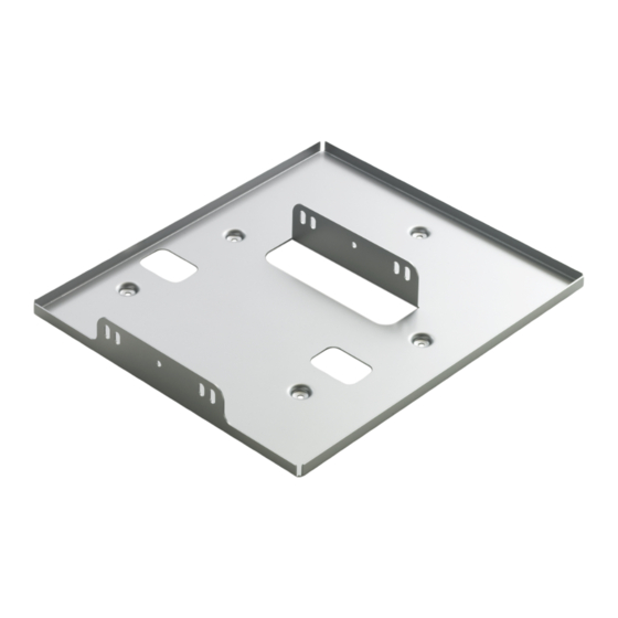
Installation method Installing the brackets to the projector Mount the ceiling bracket components onto the projector (sold separately). Place the projector on a soft cloth or a similar sur- Projector mount bracket face, with the bottom surface of the projector facing upwards. -
Page 10: Suspending The Projector
Installation method (Continued) Suspending the projector • WHEN INSTALLED USING CEILING BRACKETS FOR HIGH CEILINGS A Install the projector to the pole base by fitting the FRONT display adjustable hook part of the angle adjusting bracket over the hex head bolts. Attention z Check that the thread ridges of the temporarily fastened captive washer hex head bolts are tightly... -
Page 11: Adjusting The Installation Angle
Adjusting the installation angle z It is possible to adjust the horizontal swing and also the horizontal and vertical rotation of the ceiling mount bracket. Adjustments should be carried out in order to make the center of the projector lens perpendicular to the surface of the projection screen. - Page 12 Adjusting the installation angle (Continued) When installed using ceiling brackets for low ceilings ■If the picture is too far to the left or right of the screen A Loosen the hex bolts at the ceiling of the after- Hex nut retaining plate at four places and then move the projector ceiling mount bolt to the left or right to adjust so that the center of...
-
Page 13: Attaching The Drop Prevention Set To The Ceiling
Attaching the drop prevention set to the ceiling Within 500 mm Within 500 mm <Work procedures> (19-11/16") (19-11/16") A Mount the anchoring nuts or curled plugs (M8 or 5/16") (recommended) (recommended) in the stable ceiling surface (position shown in left fig- ure). - Page 14 Dispose of the packaging materials properly after taking the product out of it. ■Disposal When discarding this product, please contact your local authorities or dealer and ask for the correct method of disposal. Web Site : https://panasonic.net/cns/projector/ © Panasonic Corporation 2010...