Table of Contents
Advertisement
Quick Links
Advertisement
Table of Contents

Related Manuals for Motorola MPMC221


Summary of Contents for Motorola MPMC221
- Page 1 MPMC221 and MPMC222 FDDI Adapter Installation and Use PMC221A/IH1...
- Page 2 Motorola, Inc. assumes no liability resulting from any omissions in this document, or from the use of the information obtained therein. Motorola reserves the right to revise this document and to make changes from time to time in the content hereof without obligation of Motorola to notify any person of such revision or changes.
- Page 3 PCI Bus FDDI Adapter UserÕs Guide. ¨ Motorola and the Motorola symbol are registered trademarks of Motorola, Inc. AIXª is a trademarks of IBM. All other products mentioned in this document are trademarks or registered trademarks of their respective holders.
- Page 4 Related Documentation The publications listed below provide additional information pertinent to this document. Document Title Publication Number PCI Local Bus SpeciÞcation Rev 2.0; PCI Special Interest Group PCI Rev 2.0 Common Mezzanine Card SpeciÞcation; IEEE P1386 Draft 1.5 PCI Mezzanine Card SpeciÞcation; IEEE P1386.1 Draft 1.5 MC68840 IFDDI UserÕs Manual MC68840UM/AD...
- Page 5 Acronyms and Terminology The following acronyms and terminology are often used in this manual instead of the complete title or name: Dual Attachment Station FDDI Fiber Distributed Data Interface IFDDI Integrated FDDI Local Area Network Media Interface Connector Optical Bypass Relay Peripheral Component Interface Physical Layer Protocol PCI Mezzanine Card...
- Page 6 Conventions The following conventions are used in this document: bold is used for user input, as well as for the names of programs, directories, files, commands, and options and arguments to commands. italic is used for names of variables to which you assign values. Italic is also used for comments in screen displays and examples.
- Page 7 Motorola, Inc. assumes no liability for the customer's failure to comply with these requirements. The safety precautions listed below represent warnings of certain dangers of which Motorola is aware. You, as the user of the product, should follow these warnings and all other safety precautions necessary for the safe operation of the equipment in your operating environment.
- Page 8 All Motorola printed wiring boards are manufactured by UL-recognized manufacturers, with a ßammability rating of 94V-0. This equipment generates, uses, and can radiate electro- magnetic energy. It may cause or be susceptible to electro-magnetic interference (EMI) if not installed and Warning used in a cabinet with adequate EMI protection.
-
Page 9: Table Of Contents
About the OBR 2-6 Connecting the MPMC222 FDDI adapter to the OBR 2-6 Connecting the OBR to the Network 2-7 MPMC222 DAS without an OBR 2-9 Starting the MPMC221/MPMC222 2-10 Installing the AIX Driver 2-10 ConÞguring the MPMC221/MPMC222 2-10 Overview 3-1... - Page 10 MPMC222 Board Layout and Front Panel 1-4 FDDI LAN Components 1-8 Station Bypass Operation 1-10 Installing the MPMC221/MPMC222 on the Carrier Board 2-4 MPMC221 SAS Cabling 2-5 MPMC222 DAS Optical Bypass Relay Cabling 2-7 Fiber Optic Connections for MPMC222 with OBRs 2-8...
-
Page 11: Overview
This board connects to a dual-ring FDDI network. Each ring connection requires one optical transceiver. Product Features The MPMC221 and MPMC222 FDDI adapters have the following capabilities: Single-wide PMC module 100 Mb/s FDDI Single and dual-attach connectivity... -
Page 12: Aix Driver
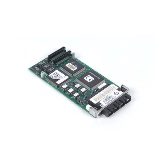
Figure 1-2 shows the MPMC222 component layout and front panel. AIX Driver The device driver for the MC68840 Controller on the MPMC221/MPMC222 is supplied with AIX 4.1.4 R4 or later releases. System Requirements Minimum system requirements to operate the MPMC221/... - Page 13 System Requirements 11717 9701 Figure 1-1. MPMC221 Board Layout and Front Panel...
- Page 14 Introduction 1952 9611 Figure 1-2. MPMC222 Board Layout and Front Panel...
- Page 15 Specifications Specifications The MPMC221/MPMC222 specifications are shown in the following table: Form Factor Single-wide PCI Mezzanine Card (PMC) Dimensions 2.9 inches wide (74 mm) 5.9 inches long (149 mm) Host Bus Interface PCI Local Bus SpeciÞcation, Rev 2.0 IEEE Compliance IEEE P1386 Common Mezzanine Card and IEEE P1386.1 PCI Mezzanine Card...
-
Page 16: Operating Environment
Introduction The MPMC221/MPMC222 exceed the maximum power dissipation as stated in the CMC Standard (IEEE P1386 Draft 2.0). The system designer should follow the Warning recommendation as stated in the PMC Standard (IEEE P1386.1 Draft 2.0). Operating Environment The MPMC221/MPMC222 requires the following operating... - Page 17 Characteristics of FDDI technology FDDI LANs offer high security and safety. The fiber-optic media does not emit or degrade from electromagnetic radiation. It does not corrode or present a shock hazard. An FDDI LAN requires two independent data paths: the primary and secondary rings.
- Page 18 Introduction An SAS device can be connected SAS = Single-Attached Station to either the Primary or Secondary DAC = Dual-Attached Concentrator ring. DAS = Dual-Attached Station OBR = Optical Bypass Relay Switch Host - Router Primary Ring FDDI Secondary Ring Dual-homed slave, with 2 masters 11718 9701 Figure 1-3.
-
Page 19: Fiber Optic Considerations
Fiber Optic Considerations Fiber Optic Considerations Fiber Optic Cable Compatibility Any standard small configuration (SC) cable assembly is compatible with the MPMC221/MPMC222, if the station-connection terminal has two standard Media Interface Connectors (MIC) with a fixed shroud enclosure. Optical Bypass Relay An external Optical Bypass Relay (OBR) is used for DAS fiber configurations with the MPMC222. -
Page 20: Optical Transceivers
On the adapter, each transceiver typically connects to the FDDI LAN through an optical bypass relay. The MPMC221 has only one optical transceiver and therefore can not be used with an optical bypass relay. -
Page 21: Fiber Optic Transmitter
Fiber Optic Considerations Fiber Optic Transmitter A fiber optic transmitter accepts a differential signal from the PHY and, using a light-emitting diode (LED), converts it into optical output for transmission through the fiber optic cable. 1-11... -
Page 23: Introduction
This chapter contains instructions for installing the MPMC221 and MPMC222 FDDI adapters onto a carrier board. Installation and Configuration Tasks Perform the following tasks to install and configure the MPMC221/ MPMC222: Install the MPMC221/MPMC222 on the carrier board per the instructions in Installing the Adapter on the Carrier Board on page 2-2. -
Page 24: Packaging
Installation Packaging The MPMC221/MPMC222 is packed in an anti-static package to protect it from any static discharge. Observe standard handling practices of static sensitive equipment. Electro-static Discharge Precautions Motorola strongly recommends that you use an antistatic wrist Use ESD strap and a conductive foam pad when installing the MPMC221/MPMC222. - Page 25 Refer to Figure 2-1 when performing steps 7, 8, and 9. 7. Insert the FDDI external connectors (U4 on the MPMC221, U4 and U13 on the MPMC222) through the PMC connector slot on the carrier board front panel. 8. Align the keying hole and connectors P11 and P12 on the MPMC221/MPMC222 over the keying pin and the PMC connectors on the carrier board.
- Page 26 Installation KEYING HOLE KEYING PIN 1953 9611 Figure 2-1. Installing the MPMC221/MPMC222 on the Carrier Board...
-
Page 27: Connecting To The Fddi Network
Connecting to the FDDI Network Connecting to the FDDI Network MPMC221 SAS For a SAS configuration, connect the S port on the MPMC221 directly to an M port of a concentrator. Figure 2-2 shows a typical SAS cable configuration. to FDDI Network... -
Page 28: Mpmc222 Das With An Obr
Installation MPMC222 DAS with an OBR To operate the MPMC222 with an OBR, connect the OBR cables to the MPMC222, and connect the fiber optic LAN cabling to the OBR. An adapter cable may be required, depending upon the type of connector available on your OBR. -
Page 29: Connecting The Obr To The Network
Connecting to the FDDI Network MPMC222 Front Panel Duplex SC PHY B PHY A Duplex SC Optical Bypass Relay Switch OBR connector 11721 9701 Figure 2-3. MPMC222 DAS Optical Bypass Relay Cabling 4. Insert the switch-control cable plug into the OBR jack, P1, on the MPMC222, as shown in Figure 2-3. - Page 30 Installation After everything is connected, verify that one hostÕs port A is always connected to the other hostÕs port B and vice versa. To install the fiber optic cables, insert the A plug of one cable and the B plug of the other cable into their matching OBR module jacks, as shown in Figure 2-4.
-
Page 31: Mpmc222 Das Without An Obr
Connecting to the FDDI Network MPMC222 DAS without an OBR If an OBR is not to be used, connect PHY A of the first host to PHY B of the second host. On the second host, connect PHY A to the PHY B of the third host. -
Page 32: Starting The Mpmc221/Mpmc222
AIX driver per the instructions in Chapter 3. You do not need to install the AIX driver if the MPMC221/ MPMC222 is installed in the system when AIX is installed and configured. The correct FDDI driver is installed automatically during Initial Program Load (IPL). -
Page 33: Overview
3AIX Driver Installation Overview This chapter describes installation of the AIX device driver. Before installing the AIX device driver, install the MPMC221/ MPMC222 on the carrier board per the instructions in Chapter 2, and install the carrier board into the system chassis. - Page 34 AIX Driver Installation 7. Answer the following questions as shown: {devices.pci.12110022} SOFTWARE to install [yes] AUTOMATICALLY install requisite software?: Leave the default values in the other fields. 8. Press Enter. SMIT returns an ok command status message when the process is complete. 9.
- Page 35 AOptical Bypass Relay Connector The optical bypass relay is controlled through a cable that connects to the OBR jack, P1, on the MPMC222 front panel. Figure A-1 shows the pins on the OBR jack. Table A-1 shows the pin assignments for the OBR cable.
- Page 37 BFront Panel LEDs Use the green and yellow LEDs on the MPMC221/MPMC222 to troubleshoot network problems. Use Table B-1 to interpret the LEDs. Table B-1. Front Panel LEDs LED Status Board Control Register Description Status Yellow Green Bit 0 Bit 1...
- Page 39 1-3, 1-4 bypass-to-network connection 1-9 electro-static discharge (ESD) 2-2 environment 1-6 ESD precautions 2-2 cables Ethernet 1-6 MPMC221 SAS 2-5 MPMC222 DAS with an OBR FDDI LAN 1-6 MPMC222 DAS without an components dia- OBR 2-9 gram 1-8...
- Page 40 Index AIX driver 3-1 DAS adapter, PMC 1-1 MPMC221/MPMC222 2-2 SAS adapter, PMC 1-1 secondary enable A-1 secondary rings 1-7 memory requirements 1-2 specifications 1-5 MIC-to-MIC cables 2-7 station bypass operation 1-10 MPMC221 1-1 system requirements 1-2 cables 2-5 MPMC222 1-1...