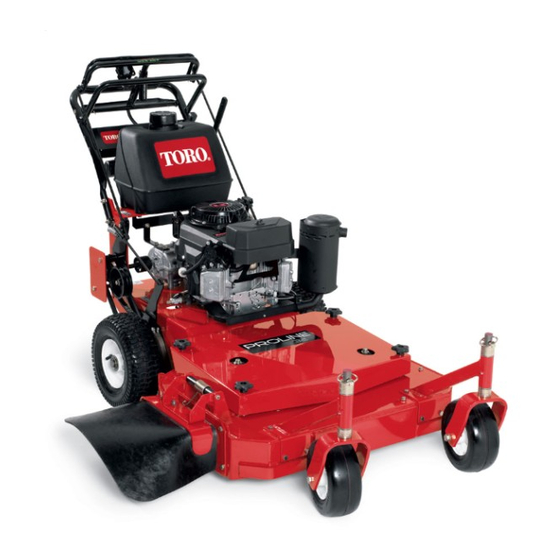
Toro 30672 Operator's Manual
Commercial walk-behind mower, fixed deck, t-bar, gear drive with 32in or 36in cutting unit
Hide thumbs
Also See for 30672:
- Operator's manual (48 pages) ,
- Operator's manual (48 pages) ,
- Operator's manual (48 pages)
Table of Contents
Advertisement
Quick Links
Advertisement
Table of Contents

Related Manuals for Toro 30672


Summary of Contents for Toro 30672
- Page 1 Form No. 3435-870 Rev A Commercial Walk-Behind Mower Fixed Deck, T-Bar, Gear Drive with 32in or 36in Cutting Unit Model No. 30672—Serial No. 405670000 and Up Model No. 39674—Serial No. 405670000 and Up *3435-870* A Register at www.Toro.com. Original Instructions (EN)
- Page 2 Whenever you need service, genuine Toro parts, or additional information, contact an Authorized Service Dealer or Toro Customer Service and have the model and serial numbers of your product ready. Figure 1 identifies the location of the model and serial numbers on the product.
-
Page 3: Table Of Contents
Contents Replacing the Traction-Drive Belt...... 34 Replacing the Drive Belt ........34 Replacing the Mower Belt ......... 35 Safety ............... 4 Adjusting the Mower Belt Tension ..... 35 General Safety........... 4 Adjusting the PTO-Engagement Safety and Instructional Decals ......4 Linkage ............ -
Page 4: Safety
Safety • Keep bystanders and children out of the operating area. Do not allow children to operate the machine. Allow only people who are responsible, trained, This machine has been designed in accordance with familiar with the instructions, and physically ANSI B71.4-2017. - Page 5 decal98-3296 98-3296 1. Belt routing 2. Engine decal93-7442 93-7442 1. Parking brake decal98-5130 98-5130 1. Warning—read the Operator's Manual for instructions on torquing the blade bolt/nut to 102 to 106 N∙m (75 to 80 ft-lb). decal106-5517 106-5517 decal95-5537(gear) 95-5537 1. Warning—do not touch the hot surface. 1.
- Page 6 decal112-9028 112-9028 1. Warning—stay away from moving parts; keep all guards and shields in place. decal121-6049 121–6049 1. Thrown object 3. Cutting/dismemberment decal131-1180 131-1180 hazard—keep bystanders hazard of hand or foot, away. mower blade—stay away 1. Read the Operator's 3. Bagging setting from moving parts.
- Page 7 decal133-8062 133-8062 decal132-4708 132-4708 1. Attention—do not adjust 2. Stop moving before the shift lever while adjusting the shift lever. moving. decal130-8374 130-8374 1. Fast 3. Engine—stop 4. Engine—slow 2. Slow...
- Page 8 decal140-1877 140-1877 1. Warning—read the Operator’s Manual. 5. Cutting/dismemberment hazard of hand or foot, mower blade—stay away from moving parts; keep all guards and shields in place. 2. Warning—all operators should be trained before operating 6. Thrown object hazard—keep bystanders away. the machine.
-
Page 9: Product Overview
Controls Product Overview Become familiar with all the controls before you start the engine and operate the machine. Control Panel g306582 Figure 3 1. Side discharge 5. T-bar control 2. Mower deck 6. Handle 3. Spark plug 7. Recoil-start handle 4. -
Page 10: Specifications
Contact Use the choke to start a cold engine. your Authorized Service Dealer or authorized Toro distributor or go to www.Toro.com for a list of all Blade-Control Bail approved attachments and accessories. To ensure optimum performance and continued safety... -
Page 11: Before Operation
Operation • If you spill fuel, do not attempt to start the engine; avoid creating a source of ignition until the fuel vapors have dissipated. Note: Determine the left and right sides of the • Do not fill containers inside a vehicle or on a truck machine from the normal operating position. -
Page 12: Performing Daily Maintenance
Testing the Safety-Interlock Note: A fuel stabilizer/conditioner is most effective when mixed with fresh fuel. To minimize System the chance of varnish deposits in the fuel system, use fuel stabilizer at all times. Test the safety-interlock system each time before you use the machine. - Page 13 Avoid making sudden changes in speed or direction; turn slowly and gradually. – Use only accessories and attachments approved by The Toro® Company. • Do not operate a machine under any conditions where traction, steering or stability is in question.
-
Page 14: Operating The Parking Brake
Starting the Engine • If you lose control of the machine, step away from the direction of travel of the machine. Connect the spark-plug wires. • Always keep the machine in gear when going Open the fuel valve. down slopes. Do not coast downhill (applicable only to gear-drive units). -
Page 15: Shutting Off The Engine
Shutting Off the Engine Operating the Blade-Control Lever (PTO) Important: In an emergency, you can stop the engine immediately by turning the ignition key to The blade-control lever (PTO) engages and the Off position. disengages power to the mower blades. Move the throttle lever to the S position (Figure... -
Page 16: Driving The Machine
Driving the Machine Using the Lower Control The throttle control regulates the engine speed (rpm). Move the throttle control to the F position for the This procedure is for driving up a curb. You can do best mowing performance. this while driving forward or backward. WARNING Note: Some curbs do not allow the rear drive tires to... -
Page 17: Stopping The Machine
g001452 Figure 10 1. Lower control 2. Handle bar—engaged g000211 Figure 9 1. Lower control 3. Lower control bar—engaged and the bar—engaged and the Stopping the Machine machine going reverse machine going forward 2. Pull up to assist the machine. CAUTION You or bystanders may be injured if you move Driving Backward up a Curb... -
Page 18: Positioning The Flow Baffle
Position B Use this position when bagging. g012676 Figure 11 1. Slot 2. Nut g012678 Figure 13 Positioning the Flow Baffle The following figures are only recommendations for use. Adjustments vary by grass type, moisture Position C content, and the height of the grass. This is the full open position. -
Page 19: Side Discharging Or Mulching Grass
Side Discharging or Mulching Grass This mower has a hinged grass deflector that disperses clippings to the side and down toward the turf. DANGER Without the grass deflector, discharge cover, or complete grass catcher assembly mounted in place, you and bystanders are exposed to blade contact and thrown debris. - Page 20 Adjusting the Caster Position Using the Height-of-Cut Chart (page 22), adjust the caster spacers to match with the axle hole selected (Figure 17). g001455 Figure 16 1. Axle-pivot bolt 2. Axle-adjustment bolt Place a jack under the rear center of the engine frame.
-
Page 21: Adjusting The Control Rods
Adjusting the Control Rods With the wheel drive fully engaged, check the gap between the upper control bar and the fixed bar. The gap needs to be approximately 25 to 32 mm (1 to 1-1/4 inches) as shown in Figure Note: The upper control bar and the fixed bar must be parallel in the engaged, relaxed, and... -
Page 22: Height-Of-Cut Chart
Height-of-Cut Chart Number of spacers Number of 1/4-inch blade spacers below the spindle below the caster 13 mm 5 mm Axle (1/2 (3/16 position inch) inch) 32 mm (1-1/4 38 mm (1-1/2 45 mm (1-3/4 26 mm (1 inch) 51 mm (2 inches) inches) inches) inches) -
Page 23: After Operation
After Operation After Operation Safety General Safety • Always shut off the machine, remove the ignition key (if equipped), wait for all moving parts to stop, and allow the machine to cool before adjusting, servicing, cleaning, or storing it. • Clean grass and debris from the machine to help prevent fires. -
Page 24: Maintenance
Do not allow untrained personnel to service the • To ensure safe, optimal performance of the machine. machine, use only genuine Toro replacement • If the engine must be running to perform a parts. Replacement parts made by other maintenance adjustment, keep your hands, feet,... -
Page 25: Lubrication
Maintenance Service Maintenance Procedure Interval • Replace the paper air-cleaner element. • Change the engine-oil filter. Every 200 hours • Replace the fuel filter. • Replace the fuel-vent filter. • Grease the transmission couplers (more often in dirty or dusty conditions). Every 250 hours •... -
Page 26: Greasing The Transmission Couplers
Greasing the Transmission Engine Maintenance Couplers Engine Safety Lubricate the transmission couplers and idler-arm pivots located at the rear of the machine (Figure 21). • Do not change the governor speed or overspeed the engine. • Run the engine dry or remove the fuel with a hand pump;... -
Page 27: Servicing The Engine Oil
Servicing the Engine Oil Note: Change the oil more frequently when the operating conditions are extremely dusty or sandy. Engine-Oil Specifications Engine-Oil Type: Detergent oil (API service SF, SG, SH, SJ, or SL) Crankcase Capacity: 1.7 L (58 oz) with the filter removed;... - Page 28 g306583 Figure 25 1. Oil dipstick 2. Filler tube Unscrew the oil dipstick and wipe the end clean (Figure 25). Slide the oil dipstick into the filler tube fully, but do not thread it onto the tube (Figure 25). g001466 Figure 26 Pull the dipstick out and look at the end.
-
Page 29: Servicing The Spark Plugs
Checking the Spark Plugs Install the replacement oil filter to the filter adapter, turn the oil filter clockwise until the Important: Do not clean the spark plugs. Always rubber gasket contacts the filter adapter, and replace the spark plugs when they have: a black tighten the filter an additional 3/4 turn (Figure coating, worn electrodes, an oily film, or cracks. -
Page 30: Fuel System Maintenance
Fuel System Maintenance DANGER In certain conditions, fuel is extremely flammable and highly explosive. A fire or explosion from fuel can burn you and others and can damage property. Refer to Fuel Safety (page 11) for a complete list of fuel related precautions. g005243 Figure 31 Servicing the Fuel System... -
Page 31: Drive System Maintenance
Drive System Install a new filter and move the hose clamps close to the filter. Maintenance Open the fuel-shutoff valve at the fuel tank (Figure 31). Check for fuel leaks and repair, if needed. Checking the Tire Pressure Wipe up any spilled fuel. Service Interval: Every 50 hours/Monthly (whichever comes first) Servicing the Fuel-Vent System... -
Page 32: Cooling System Maintenance
Cooling System Maintenance Cleaning the Air-Intake Screen Remove any buildup of grass, dirt, or other debris from the cylinder and cylinder head cooling fins, the air-intake screen on the flywheel end, and the carburetor-governor levers and linkage. This helps ensure adequate cooling and correct engine speed to reduce the possibility of overheating or mechanical damage to the engine. -
Page 33: Brake Maintenance
Brake Maintenance Check the brake before you adjust it; refer to Checking the Parking Brake (page 33). Disengage the parking brake. Servicing the Parking Brake To adjust the brake, rotate the wing nuts on the brake rods (Figure 36). Check the brakes on both a level surface and a slope. Turn the wing nuts clockwise to tighten the brake Always engage the parking brake when you stop the and counterclockwise to loosen the brake. -
Page 34: Belt Maintenance
Belt Maintenance Inspecting the Belts Service Interval: Every 25 hours—Check the belts for wear or cracks. Replace the belt if it is worn. The signs of a worn belt include squealing while the belt is rotating; the blades slipping while cutting grass; and frayed edges, burn marks, and cracks on the belt. -
Page 35: Replacing The Mower Belt
Install the mower belt (Figure 38). Remove the hairpin cotter and clevis pin from the bell crank (Figure 39). Check the belt guide under the engine frame for the proper adjustment (Figure 38). Rotate the clevis clockwise on the rod to increase the clearance;... -
Page 36: Adjusting The Pto-Engagement Linkage
Adjusting the Important: The belt must be tight enough to not slip during heavy loads, while cutting grass. PTO-Engagement Linkage Over-tensioning the belt reduces the life of the spindle bearing, belt, and idler pulley. The adjustment for the PTO-engagement linkage is Park the machine on a level surface, disengage located beneath the front, left corner of the engine the PTO, and engage the parking brake. -
Page 37: Adjusting The Pto-Safety Switch
Adjusting the PTO-Safety Switch Park the machine on a level surface, disengage the PTO, and engage the parking brake. Shut off the engine, remove the key, and wait for all moving parts to stop before leaving the operating position. Ensure that the assist arm is against the front assist-arm stop. -
Page 38: Mower Deck Maintenance
Mower Deck Maintenance Blade Safety A worn or damaged blade can break and a piece could be thrown toward you or bystanders, resulting in serious personal injury or death. g006530 Figure 45 • Inspect the blades periodically for excessive wear 1. - Page 39 To ensure optimum g000552 performance and continued safety conformance of Figure 48 the machine, use genuine Toro replacement blades. 1. Sharpen at original angle. Replacement blades made by other manufacturers may result in non-conformance with safety standards.
-
Page 40: Adjusting The Blade Brake
Adjusting the Blade Brake Replacing the Grass Deflector Park the machine on a level surface, disengage the PTO, and engage the parking brake. Shut off the engine, remove the key, and WARNING disconnect the spark-plug wires from the spark An uncovered discharge opening could allow plugs. -
Page 41: Cleaning
Cleaning Place one J-hook end of the spring around the grass deflector (Figure 51). Important: The grass deflector must be Cleaning under the Mower able to rotate. Lift the deflector up to the fully-open position and ensure that it rotates Service Interval: Before each use or daily into the fully-down position. -
Page 42: Storage
Storage Dispose of fuel properly. Recycle the fuel according to local codes. Important: Do not store fuel containing Cleaning and Storing the stabilizer/conditioner longer than the duration recommended by the Machine fuel-stabilizer manufacturer. Park the machine on a level surface, disengage Remove and check the condition of the spark the PTO, and engage the parking brake. -
Page 43: Troubleshooting
Troubleshooting Problem Possible Cause Corrective Action The fuel tank is showing signs of collapsing 1. The air-cleaner paper element clogged. 1. Clean the paper element. or the machine is frequently showing signs of running out of fuel. The engine overheats. 1. - Page 44 Problem Possible Cause Corrective Action The machine vibrates abnormally. 1. The cutting blade(s) is/are bent or 1. Install new cutting blade(s). unbalanced. 2. The blade mounting bolt is loose. 2. Tighten the blade mounting bolt. 3. The engine mounting bolts are loose. 3.
-
Page 45: Schematics
Schematics g001471 Electrical Schematic (Rev. -A) - Page 46 Notes:...
- Page 47 Notes:...
- Page 48 While the exposure from Toro products may be negligible or well within the “no significant risk” range, out of an abundance of caution, Toro has elected to provide the Prop 65 warnings. Moreover, if Toro does not provide these warnings, it could be sued by the State of California or by private parties seeking to enforce Prop 65 and subject to substantial penalties.