
Related Manuals for Mitsubishi Electric FR-HC2 Series


Summary of Contents for Mitsubishi Electric FR-HC2 Series
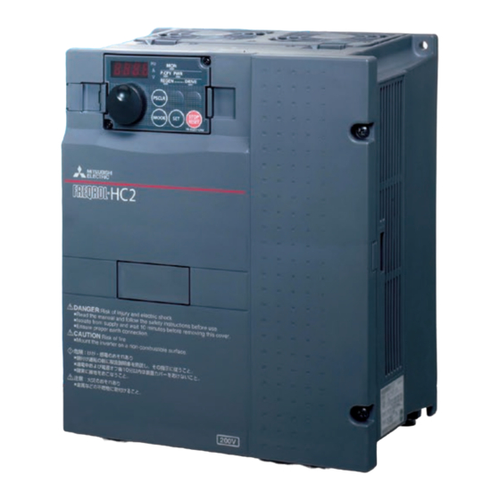
- Page 1 FACTORY AUTOMATION HIGH POWER FACTOR CONVERTER FR-HC2 Effective suppression of inverter's power supply harmonics...
- Page 2 Global Player GLOBAL IMPACT OF MITSUBISHI ELECTRIC Through Mitsubishi Electric’s vision, “Changes for the Better“ are possible for a brighter future. Mitsubishi Electric is involved in many areas including the following We bring together the best minds to Energy and Electric Systems create the best technologies.
-
Page 3: Table Of Contents
Contents Features Connection example Standard specifications Outline dimension drawings Terminal connection diagram, Terminal specification explanation Parameter list Protective functions Option and peripheral devices Precaution on selection and operation Warranty... - Page 4 Features Greatly suppressed power supply harmonics The HC2 converters, being the self-excitation three-phase bridge circuit under "the Harmonic Suppression Guidelines for Specific Consumers", take the conversion coefficient of the equivalent capacity (K5 = 0). Harmonic Conversion Coefficient of the Equivalent Capacity (Excerpt from the Guidelines Appendix) Classification Circuit type...
- Page 5 Features Operation panel equipped with the setting dial Supporting more network protocols (FR-DU07-CNV) Parameters can be copied using the operation panel HC2 supports RS-485 as a standard. With the option (FR-DU07-CNV). FR-A7NC, HC2 also supports CC-Link. The setting values of the parameters can be stored to the •The power can be monitored during driving/regenerative operation panel and the option parameter unit (FR-PU07).
-
Page 6: Connection Example
Connection example Three-phase AC power supply Use within the permissible power supply specifications of the converter. Moulded case circuit breaker (MCCB), earth leakage current breaker (ELB), or fuse The breaker must be selected carefully since an inrush current flows in the converter at power ON. - Page 7 Standard specifications Standard specification rating 200V Model name FR-HC2-K Applicable inverter capacity (kW) Rated output capacity (kW) 10.7 19.8 Rated input voltage (V) Three-phase 200V to 220V 50Hz/200V to 230V 60Hz Rated input current (A) Overload current rating 150% 60s ...
- Page 8 Common specifications Control method PWM control Power supply frequency range 50Hz to 60Hz Current limit level Current limit value selectable (0 to 220% variable) The following signals can be assigned to Pr. 3 to Pr. 7 (input terminal function selection): converter Input signal (Five terminal) stop, monitor switching, converter reset, external thermal relay, and inrush resistance overheat detection.
- Page 9 Checking peripheral devices Peripheral devices Always install the included peripheral devices. Check the model name of the each peripheral device. For the 400V class peripheral devices, H is indicated in front of the model name. FR-HC2-7.5K to 75K, FR-HC2-H7.5K to H220K Peripheral Device Description Quantity...
- Page 10 Selection of the high power factor converter and the inverter The required converter capacity differs by the multiple rating selection setting of the inverter. Refer to the following table for the connectable inverter capacities when connecting one inverter to a high power factor converter.
- Page 11 When the applicable motor capacity is lower than the inverter capacity (FR-A800 (HD rating)). 2.2K Inverter capacity 3.7K 5.5K 7.5K 18.5K lower FR-HC2-7.5K — ...
- Page 12 Wiring of several inverters to one converter Up to ten inverters can be connected to one converter. Be sure to use a high power factor converter with the capacity equal to or higher than the total capacity of inverters/motors. Additionally, the total capacity of the inverters or motors needs to be equal ≤...
-
Page 13: Outline Dimension Drawings
Outline dimension drawings Converter (FR-HC2) FR-HC2-75K or lower FR-HC2-H160 to H560K FR-HC2-H110K or lower (Dimension drawing example: FR-HC2-H560K) (Dimension drawing example: FR-HC2-7.5K) P.CPY PWR REGEN DRIVE 2-φd hole 3-φd hole PSCLR 200V class 400V class Model Model FR-HC2-7.5K FR-HC2-H7.5K, H15K FR-HC2-15K FR-HC2-H30K FR-HC2-30K... - Page 14 Reactor 2 (FR-HCL22) (Dimension drawing example : FR-HCL22-7.5K) MAX D MAX W 4-d hole 200V class 400V class Model W D Model W D FR-HCL22-7.5K 237.5 210 230 140 110 FR-HCL22-H7.5K 237.5 210 220 140 110 1.5 1.5 1.5 1.5 FR-HCL22-15K 257.5 230...
- Page 15 Filter capacitor (FR-HCC2) FR-HCC2-H280K FR-HCC2-H400K 2-15 20 oval-shaped hole Enlarged drawing of the installation foot (Recommended bolt size: M12) Enlarged drawing of the installation foot (Recommended bolt size: M12) R7.5 370 3 394 3 102.5 52.5 90 5 90 5 M12 bolt 90 5 90 5 2-15 20...
- Page 16 Terminal block shorting conductor (C152C481H21) MC shorting conductor (C152C423H21) (FR-HCM2-H280K) (FR-HCM2-H400K, H560K) 80 0.4 60 0.4 40 0.4 5-oval 7-8 20 0.3 (2.3) 9-M5 screw for installation of 57.5 (57.5) inrush resistor 4- 14 hole (M12) Sectional view of A - A (Unit: mm) (Unit: mm) Mass: 1.6kg...
- Page 17 Protruding the heatsink When installing a converter inside an enclosure, the heat generated in the enclosure can be greatly reduced by protruding the heatsink of the converter. This installation method is recommended when downsizing the enclosure and such. When using a heatsink protrusion attachment (FR-A7CN) For the FR-HC2-7.5K to 75K and FR-HC2-H7.5K to H110K, a heatsink can be protruded outside the enclosure using a heatsink protrusion attachment (FR-A7CN).
- Page 18 Heatsink protrusion for 160K or higher (1) Enclosure cut Cut the enclosure according to the capacity of the converter. FR-HC2-H160K, H220K FR-HC2-H280K FR-HC2-H400K, H560K 6-M10 screw 6-M10 screw 6-M10 screw Hole Hole Hole (2) Moving and removing the back installation frames ...
- Page 19 Terminal connection diagram (when using with the FR-A800 series) Before making connections, check the cable size and connection method to each device in the Instruction Manual. FR-HC2-7.5K to 75K, FR-HC2-H7.5K to H220K Outside box (FR-HCB2) Converter Limit resistor (FR-HC2) Reactor2 Reactor1 Inverter...
- Page 20 FR-HC2-H400K, H560K Limit resistor Converter Inverter (FR-HC2) Reactor 2 Reactor 1 (FR-HCL22) (FR-HCL21) MCCB R/L1 R4/L14 S/L2 Motor Power T/L3 S4/L24 Supply R1/L11 S1/L21 T4/L34 Earth Fuses (Ground) Limit resistor (with thermostat) (NC contact) 3 Filter capacitors (FR-HCC2) Relay output...
- Page 21 Terminal specification explanation Terminal Type Terminal Name Description Symbol These terminals are used to detect power phase and power voltage, and to input control power. Connect them R/L1, S/L2, Power input to the commercial power supply. If the inverter is operated without connecting them to the commercial power T/L3 supply, the converter will be damaged.
- Page 22 Terminal Type Terminal Name Description Symbol Multi-purpose Output item: Y5 signal (output voltage match) (initial setting) ermissible load: 24VDC Turns ON when the detected bus voltage equals to the commanded bus voltage. 0.1A output 3 Open collector Common terminal for terminal Y3 output common With the PU connector, communication can be made through RS-485.
-
Page 23: Parameter List
Parameter list REMARKS indicates simple mode parameters. The parameters shaded in allow their settings to be changed during operation even if "1" (write disabled) is set to Pr. 77 Parameter write selection. Customer Parameter Name Range Increments Initial value setting ... - Page 24 Customer Parameter Name Range Increments Initial value setting Free parameter 1 0 to 9999 9999 Free parameter 2 0 to 9999 9999 Key lock operation selection 0, 10 65 Retry selection 0, 1, 2, 3, 4 67 Number of retries at fault occurrence 0 to 10, 101 to 110 ...
-
Page 25: Protective Functions
Protective functions When a fault occurs in the converter, the protective function activates to trip the converter, and the PU display automatically changes to one of the following fault or alarm indications. Operation Panel Indication Name E — — — Faults history HOLD Operation panel lock... -
Page 26: Option And Peripheral Devices
Option and peripheral devices Option List Applicable Name Type Applications, Specifications, etc. converter Converter operation, monitoring, and parameter setting can be Shared among CC-Link communication FR-A7NC commanded from a programmable controller. all models Parameter unit Shared among FR-PU07 Interactive parameter unit with LCD display (8 languages) all models Parameter unit with battery... - Page 27 Circuit breakers and magnetic contactors Check the model of the converter and select peripheral devices according to the capacity. Refer to the table below to prepare appropriate peripheral devices. 200V class Moulded Case Circuit Breaker (MCCB) Magnetic or Earth Leakage Circuit Breaker (ELB) Converter Model Contactor (MC) ...
- Page 28 Fuse Installation of a fuse is recommended between a high power factor converter and an inverter. Select a fuse according to the capacity of the connected motor. When using a motor, of which the capacity is smaller than the inverter capacity by two ranks or more, select the fuse with the capacity that is one rank lower than the inverter capacity. Select a fuse from the table below, and install it to both of the P side and the N side between the high power factor converter and the inverter.
- Page 29 ●Recommended noise filter Install this to reduce the electromagnetic noise. [Connection diagram] Install the noise filter composed of a common mode chokes (ring cores) and damping resistors on the input side of the high power factor converter. Use the FINEMET ® ring cores (manufactured by Hitachi Metals, Ltd.) and the FR-ABR damping resistors (inverter option) to compose the noise filter.
-
Page 30: Precaution On Selection And Operation
Precaution on selection and operation SAFETY INSTRUCTIONS To use the product safely and correctly, make sure to read the Instruction Manual before using the product. This product has not been designed or manufactured for use with any equipment or system operated under life-threatening conditions. - Page 31 Peripheral Device Selection Precautions Selection and installation of the moulded case circuit breaker Install a moulded case circuit breaker (MCCB) on the power receiving side to protect the wiring at the converter's input side. For the MCCB selection, refer to page 27. (Refer to the materials related to the breaker.) For earth leakage circuit breakers, use the harmonic/surge compatible model provided by Mitsubishi.
- Page 32 MEMO...
-
Page 33: Warranty
Warranty When using this product, make sure to understand the warranty described below. 1. Warranty period and coverage We will repair any failure or defect (hereinafter referred to as "failure") in our FA equipment (hereinafter referred to as the "Product") arisen during warranty period at no charge due to causes for which we are responsible through the distributor from which you purchased the Product or our service provider. - Page 34 MEMO...
- Page 35 MEMO...
- Page 36 Mitsubishi Electric Europe B.V. Czech Branch (Czech Republic FA Center) Nagoya, Japan Pune, Gurgaon, Bangalore, Chennai, Ahmedabad, India Mitsubishi Electric India Pvt. Ltd. Bangkok, Thailand Singapore Mitsubishi Electric Factory Automation Mitsubishi Electric (Thailand) Co., Ltd. (Thai FA Center) Asia Pte, Ltd. (ASEAN FA Center)
- Page 37 Hanoi Branch (Mexico FA Center) R: Mitsubishi Electric Vietnam Co., Ltd. Sao Paulo SP, Brazil Jakarta, Indonesia L: Mitsubishi Electric do Brasil Comércio e PT. Mitsubishi Electric Serviços Ltda. Indonesia Cikarang Office (Indonesia FA Center) R: MELCO CNC do Brasil Comércio e Serviços S.A...
- Page 38 This solution solves customers' issues and concerns by enabling visualization and analysis that lead to improvements and increase availability at production sites. Utilizing our FA and IT technologies and collaborating with e-F@ctory Alliance partners, we reduce the total cost across the entire supply chain and engineeringchain, and support the improvement initiatives and one-step-ahead manufacturing of our customers.
- Page 39 YOUR SOLUTION PARTNER Low voltage: MCCB, MCB, ACB Medium voltage: VCB, VCC Power monitoring, energy management Mitsubishi Electric offers a wide range of automation equipment from PLCs and HMIs to CNC and EDM machines. Compact and Modular Controllers A NAME TO TRUST...
- Page 40 Mitsubishi Electric Corporation Nagoya Works is a factory certified for ISO14001 (standards for environmental management systems)and ISO9001(standards for quality assurance management systems) HEAD OFFICE: TOKYO BLDG., 2-7-3, MARUNOUCHI, CHIYODA-KU, TOKYO 100-8310, JAPAN L(NA)06070ENG-B(1707)MEE...