Table of Contents
Advertisement
Quick Links
Advertisement
Table of Contents
Troubleshooting

Related Manuals for Mitsubishi Electric AnyWire NZ2AW1C2AL


Summary of Contents for Mitsubishi Electric AnyWire NZ2AW1C2AL
- Page 1 CC-Link―AnyWireASLINK Bridge Module User's Manual -NZ2AW1C2AL...
-
Page 3: Copyright
Mitsubishi Electric Corporation. PRECAUTIONS REGARDING WARRANTY AND SPECIFICATIONS The NZ2AW1C2AL was jointly developed and manufactured by Mitsubishi Electric Corporation and Anywire Corporation. Note that there are some precautions regarding warranty and specifications of this product. • Warranty... -
Page 4: Safety Precautions
SAFETY PRECAUTIONS (Read these precautions before using this product.) Before using this product, please read this manual and the relevant manuals carefully and pay full attention to safety to handle the product correctly. The precautions given in this manual are concerned with this product only. For the safety precautions of the programmable controller system, refer to the user's manual for the CPU module used. - Page 5 [Installation Precautions] CAUTION ● Use the module in an environment that meets the general specifications in this manual. Failure to do so may result in electric shock, fire, malfunction, or damage to or deterioration of the product. ● Securely fix the module with a DIN rail. ●...
- Page 6 [Wiring Precautions] CAUTION ● Individually ground the FG and LG terminals of the programmable controller with a ground resistance of 100 ohms or less. Failure to do so may result in electric shock or malfunction. ● Tighten the terminal block screws within the specified torque range. Undertightening can cause short circuit, fire, or malfunction.
- Page 7 [Startup and Maintenance Precautions] WARNING ● Do not touch any terminal while power is on. Doing so will cause electric shock or malfunction. ● Shut off the external power supply (all phases) used in the system before cleaning the module or retightening the terminal block screws.
-
Page 8: Conditions Of Use For The Product
CONDITIONS OF USE FOR THE PRODUCT (1) Mitsubishi programmable controller ("the PRODUCT") shall be used in conditions; i) where any problem, fault or failure occurring in the PRODUCT, if any, shall not lead to any major or serious accident; ii) where the backup and fail-safe function are systematically or automatically provided outside of the PRODUCT for the case of any problem, fault or failure occurring in the PRODUCT. -
Page 9: Compliance With Emc And Low Voltage Directives
DIRECTIVES Method of ensuring compliance To ensure that Mitsubishi Electric programmable controllers maintain EMC and Low Voltage Directives when incorporated into other machinery or equipment, certain measures may be necessary. Please refer to one of the following manuals. • User's manual for the CPU module or head module used •... -
Page 10: Introduction
INTRODUCTION Thank you for purchasing the CC-Link-AnyWireASLINK bridge module (hereafter abbreviated as bridge module). This manual describes the procedures, system configuration, parameter settings, functions, and troubleshooting of a bridge module. Before using this product, please read this manual and the relevant manuals carefully and develop familiarity with the functions and performance of the bridge module to handle the product correctly. -
Page 11: Relevant Manuals
RELEVANT MANUALS CC-Link Manual name (manual number) Description MELSEC iQ-R CC-Link System Master/Local Module User's Manual (Startup) Specifications, procedures before operation, system configuration, (SH-081269ENG) wiring, and communication examples of the CC-Link system master/ local module MELSEC iQ-R CC-Link System Master/Local Module User's Manual (Application) Functions, parameter settings, programming, troubleshooting, I/O (SH-081270ENG) signals, and buffer memory of the CC-Link system master/local module... - Page 12 MEMO...
-
Page 13: Table Of Contents
CONTENTS COPYRIGHT ................1 PRECAUTIONS REGARDING WARRANTY AND SPECIFICATIONS . - Page 14 CHAPTER 6 MEMORY MAP Lists of Remote I/O Signals ............. . . 40 When the CC-Link operation mode is Ver.1.10 .
- Page 15 Appendix 3 Checking Serial Number and Function Version ......... 112 Appendix 4 EMC and Low Voltage Directives .
-
Page 16: Terms
TERMS Unless otherwise specified, this manual used the following terms. Term Description Address Device information set to a slave module to identify each node on the AnyWireASLINK network Address writer A hand-held device to read/write parameters (including addresses) from/to a slave module AnyWireASLINK A system where sensors at the end of a control system are connected to a programmable controller in the most suitable way. -
Page 17: Packing List
PACKING LIST The following items are included in the package of this product. Before use, check that all the items are included. NZ2AW1C2AL NZ2AW1C2AL Before Using the Product... -
Page 18: Chapter 1 Overview
OVERVIEW The bridge module, a product of the joint development project with Anywire Corporation, allows the AnyWireASLINK system to be connected with CC-Link. The AnyWireASLINK system provides a high-speed and highly-reliable sensor system. For the CC-Link, refer to the following. ... -
Page 19: Features
Features Seamless connection between two systems CC-Link and AnyWireASLINK can be seamlessly connected. CC-Link transmission speed auto-tracking The transmission speed of the bridge module need not be set by the user since it is automatically determined according to the transmission speed set in a master station. Man-hour reduction by built-in terminating resistor Since the bridge module has a built-in terminating resistor (110) of CC-Link, a terminating resistor is not necessary even when the module is used at the end of the CC-Link network. -
Page 20: Chapter 2 Specifications
SPECIFICATIONS General Specifications The following table lists the general specifications. Item Specifications Operating ambient 0 to 55 temperature Storage ambient -25 to 75 temperature Operating ambient 10 to 95%RH, non-condensing humidity Storage ambient humidity Vibration resistance Compliant with JIS Frequency Constant Half amplitude... -
Page 21: Performance Specifications
Performance Specifications The following table lists the performance specifications. Classification Item Specifications CC-Link side Station type Remote device station CC-Link version Ver.1.10 Ver.2.00 Extended cyclic setting 2 times setting Communication speed 10M/5M/2.5M/625K/156Kbps (automatic setting) Number of occupied Remote device stations 1 to 4 are occupied 4 stations occupied (RX/RY number of occupied stations according to the setting of the specification... - Page 22 *1 When the CC-Link operation mode is set to Ver.1.10 by the operation mode setting switch, the number of occupied stations is changed by the number of transmission points setting switch. *2 Ver.1.10-compatible CC-Link dedicated cable, CC-Link dedicated cable (Ver.1.00-compatible), and CC-Link dedicated high- performance cable (Ver.1.00-compatible) cannot be used at the same time.
-
Page 23: Applicable Systems
Applicable Systems Applicable master modules Master modules that can be used are listed on the website of CC-Link Partner Association (CLPA). For the website of CC-Link Partner Association (CLPA), refer to the following. www.cc-link.org Parameter setting items according to CC-Link version For a mode setting of the master module connected with the bridge module or a station information (station type), set them in the following combinations. -
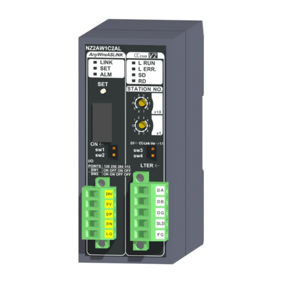
Page 24: Part Names
Part Names Name Description LED indicator The status of the bridge module is indicated by the LEDs. (CC-Link side) LED name Description L RUN LED Indicates the CC-Link communication status. (green) On: Operating normally Off: Disconnecting (timeout error) L ERR. LED Indicates the CC-Link error status. - Page 25 Name Description AnyWireASLINK side terminal A transmission cable terminal block of the AnyWireASLINK (Page 28 AnyWireASLINK Side Terminal Block) block *1 The LED may turn on for a moment when the module is powered on, however it does not affect the operation of the bridge module. *2 When station number setting switch is changed while communication is disconnected, the LED will start flashing irregularly.
-
Page 26: Chapter 3 Mounting Module
MOUNTING MODULE Mount the bridge module on a DIN rail before use. Direction of mounting a module Since the bridge module radiates heat, place it in airy place in the direction shown below. DIN rail Vertical installation (basic) Do not place the module in the directions shown below. Downward installation Horizontal installation Vertical installation (upside down) - Page 27 Mounting a module on a DIN rail Hook the upper fixing tab on the bottom of the module to the DIN rail. Push and engage the bridge module on the DIN rail. Removing a module from a DIN rail Insert a flathead screwdriver into the hook and pull the hook to remove from the DIN rail.
-
Page 28: Chapter 4 Connections
CONNECTIONS CC-Link Side Terminal Block The bridge module is handled as a remote device station of CC-Link. The CC-Link side terminal block is the connection terminal which is easy to mount or remove. Manufacturer: PHOENIX CONTACT GmbH & Co. KG (Contact: www.phoenixcotact.com) Model: MSTB2,5/5-STF-5,08AU Tightening torque: 0.2 to 0.3Nm To tighten the terminal block, a flathead screwdriver having a tipped size of 0.63.5mm is required. -
Page 29: Connecting A Cc-Link Dedicated Cable
Connecting a CC-Link dedicated cable The connection example of the CC-Link dedicated cable is shown below. CC-Link Master module NZ2AW1C2AL remote I/O module (Blue) (Blue) (Blue) (Blue) Terminating Terminating (White) (White) (White) (White) resistor resistor (Yellow) (Yellow) (Yellow) (Yellow) CC-Link dedicated CC-Link dedicated cable cable... -
Page 30: Anywireaslink Side Terminal Block
AnyWireASLINK Side Terminal Block Transmission cable terminal block Model Applicable tightening torque MC 1,5/5-STF-3,81 0.2 to 0.3Nm *1 Use the one manufactured by PHOENIX CONTACT GmbH & Co. KG. (For contact, visit www.phoenixcontact.com.) To connect the terminal block, a flathead screwdriver having a tipped size of 0.42.5mm is required. Before removing the transmission cable terminal block, check that the terminal block mounting screws on both ends are completely loosened (removed from the socket). -
Page 31: Cable Processing
Cable processing Bare cables can be connected to the transmission cable terminal block; however, for safety reasons, it is recommended to connect cables using bar solderless terminals. Use UL-listed solderless terminals and, for processing, use a tool recommended by their manufacturer. Type Model Application... -
Page 32: Connecting Slave Modules
Connecting Slave Modules Connection type Bridge module Terminating unit Slave module Multidrop Slave module Slave Slave module module Tree branch T-branch • The maximum transmission distance in the AnyWireASLINK stand-alone system is 200m, which is the total cable length including the main line and branch line. (It varies depending on the wire diameter of the transmission cables (DP, DN) or the transmission cable supply current.) •... -
Page 33: Supplying Power To A Bridge Module
Supplying Power to a Bridge Module Method of supplying the power to the bridge module Connect a 24VDC external power supply to the bridge module. The power consumed in the internal control circuits of all the slave modules of AnyWireASLINK and the external load power connected to non-isolated slave modules are supplied collectively from the 24VDC external power supply connected to the bridge module. - Page 34 ■Description of the condition 1) • Constants related to the non-isolated slave module (Ihin, Iho) In the non-isolated slave module, the current required for the internal control circuit and the connected load is supplied with transmission cables (DP, DN). Ihin(A) = Current consumption of the non-isolated input slave module/I/O combined slave module = Current consumption of the non-isolated input slave module/I/O combined slave module + Current consumption of connected load (three-wire sensor) ...
- Page 35 • Constants related to the isolated slave module (Izdin, Izdo) In the isolated slave module, only the current required for the internal control circuit is supplied with the transmission cables (DP, DN), whereas that for the connected load is supplied from the 24VDC external power supply. Izdin(A) = Internal current consumption of the isolated input slave module/I/O combined slave module Izdo(A) = Internal current consumption of the isolated output slave module Isolated slave module...
- Page 36 ■Description of the conditions 2) and 3) • Vm: Supply voltage for the bridge module Voltage: 21.6 to 27.6VDC (24VDC - 10 to + 15%), ripple voltage 0.5Vp-p or lower Recommended voltage: 26.4VDC (24VDC + 10%) • V(V): Cable-to-cable voltage drop V(V) = Transmission cable supply current I(A) ...
-
Page 37: Checking System Before Power-On
Checking System Before Power-on This section describes the items to be checked before power-on. Check that the bridge module is mounted or connected correctly. (Page 24 MOUNTING MODULE) Check that the total length of the CC-Link is within the specified range. ( User's manual for the master module used) Check that the total length of the AnyWireASLINK system is within the specified range. -
Page 38: Powering On The System
Powering on the System After checking the items described above, power on and start the system. How to power on the AnyWireASLINK system is as follows. The order is inverted when the system is powered off. 24VDC external power supply for the AnyWireASLINK system (This step is required only when the supply power of slave module is different from power supply of the bridge module. -
Page 39: Terminating Unit
Terminating Unit To ensure more stable transmission quality, connect a terminating unit to the end of a transmission cable (DP, DN). Terminating unit connection Bridge module Basic Terminating unit The end of a line Main line Connect at least one terminating unit for one AnyWireASLINK line. Important Connect it at the farthest end from the bridge module. -
Page 40: Chapter 5 Switch Setting
SWITCH SETTING CC-Link Side Station number setting switch ■Setting method Set the station number of CC-Link using the rotary switch in the front of the bridge module. Set the station number with power- off because setting value becomes effective when powered on. •... -
Page 41: Anywireaslink Side
AnyWireASLINK Side Number of transmission points setting switch Set required number of occupied stations and transmission points of CC-Link when CC-Link operation mode is performed. All switch positions are set to off when the product is shipped. CC-Link operation mode Number of occupied Number of transmission points of stations of CC-Link... -
Page 42: Chapter 6 Memory Map
MEMORY MAP The bridge module occupies 1 to 4 stations starting the station number specified in the CC-Link system. For details on buffer memory areas of the master module, refer to the user's manual for the master module used. Lists of Remote I/O Signals When the CC-Link operation mode is Ver.1.10 The following table lists remote I/O signals when the CC-Link operation mode is Ver.1.10. - Page 43 Remote I/O signals when 2 stations are occupied Both remote input (RX) and remote output (RY) of the bridge module use 64 points. Signal direction: Bridge module master module Signal direction: Master module bridge module Remote input (RX) Name Remote output (RY) Name...
- Page 44 Remote I/O signals when 4 stations are occupied Both remote input (RX) and remote output (RY) of the bridge module use 128 points. Signal direction: Bridge module master module Signal direction: Master module bridge module Remote input (RX) Name Remote output (RY) Name...
-
Page 45: When The Cc-Link Operation Mode Is Ver.2.00
When the CC-Link operation mode is Ver.2.00 The following table lists remote I/O signals when the CC-Link operation mode is Ver.2.00. Remote I/O signals when 4 stations are occupied Both remote input (RX) and remote output (RY) of the bridge module use 224 points. Signal direction: Bridge module ... -
Page 46: Lists Of Remote Register Areas
Lists of Remote Register Areas Input or output of AnyWireASLINK uses remote register areas of CC-Link. When the CC-Link operation mode is Ver.1.10 The following table lists remote register areas when the CC-Link operation mode is Ver.1.10. Remote registers when 1 station is occupied Both input and output of AnyWireASLINK use 4 words. - Page 47 Remote registers when 4 stations are occupied Both input and output of AnyWireASLINK use 16 words. Set the addresses of slave modules within the range of 0 to 255. CC-Link side remote register input AnyWireASLINK CC-Link side remote register output AnyWireASLINK side input signal side output signal...
-
Page 48: When The Cc-Link Operation Mode Is Ver.2.00
When the CC-Link operation mode is Ver.2.00 The following table lists remote register areas when the CC-Link operation mode is Ver.2.00. Remote registers when 4 stations are occupied Both input and output of AnyWireASLINK use 32 words. Set the addresses of slave modules within the range of 0 to 255. CC-Link side remote register input AnyWireASLINK CC-Link side remote register output... -
Page 49: Details Of Remote Register Areas
Details of Remote Register Areas Input signal (RWrn+0 to RWrn+15) The on/off status (on: 1, off: 0) of the input signal of the slave module is automatically stored. For a 2-point input slave module (address: 10) The two bits (A and B) of RWrn+0 are occupied for the input signal because the setting address is 10. Area with the setting address of 10 Remote register... - Page 50 Latest error ID storage area (RWrn+17) The error ID of the module targeted for the latest error code is stored. The following table lists error codes stored. Error code Error description Remote input signal turned on when the error occurs 00CAH DP/DN disconnection error Error status flag (RX(n+D)A)
- Page 51 Output signal (RWwn+0 to RWwn+15) When the on/off status data (on: 1, off: 0) of the output signal of the slave module is written from the CPU module, the slave module automatically outputs the signal. For a 2-point output slave module (address: 30) The two bits (E and F) of RWwn+1 are occupied for the output signal because the setting address is 30.
-
Page 52: Error Reset
Error Reset Remote READY turns on after power-on. Error status flag turns on when an error occurs. Error status flag is reset (on to off) by turning on error reset request flag, provided that the error cause has been removed. Remote READY is reset (on to off) when an error occurs. -
Page 53: Chapter 7 Settings Before Operation
SETTINGS BEFORE OPERATION Settings of Slave Module Slave module address setting Setting the start number of the addresses assigned for data communications is required for slave modules. An address can be written to a slave module or the address assigned to a slave module can be read through infrared communications using an address writer (manufactured by Anywire Corporation). - Page 54 ■Address setting example Assignment by 2-point slave module only Bits are occupied as follows when 0 is assigned to the address of a 2-point input slave module and 0 and 2 are assigned to the respective addresses of two 2-point output slave modules. •...
- Page 55 Slave module parameter setting Set the parameter of the slave module by using the address writer. For details, refer to the manual for the slave module used. The parameter setting of slave modules cannot be performed in the following cases. •...
-
Page 56: Automatic Address Detection
Automatic Address Detection Automatic address detection is a function to store the IDs (addresses) of the connected slave modules in the EEPROM of the bridge module. The parameters of the connected devices are automatically updated after the IDs are stored in the EEPROM of the bridge module and unset IDs (addresses) and the same IDs (addresses) are detected. - Page 57 Precautions ■The automatic address detection cannot be performed in the following cases. • When an error occurs in the AnyWireASLINK system (Example: Short-circuit, 24VDC external power supply voltage drop) • Within approximately five seconds after the AnyWireASLINK system is powered on or system reset recovery •...
- Page 58 Interlock program The interlock program described here prevents Automatic address detection command (RYn1) from being turned on while parameter access is being executed or the automatic address detection is in progress , allowing proper automatic address detection. The following shows an interlock program for when the CC-Link operation mode of the bridge module has been set to Ver.1.10 and one station has been occupied.
-
Page 59: Automatic Address Detection Execution Timing
Automatic address detection execution timing Turning on Automatic address detection command (RYn1) long press of the SET switch Automatic address detection Automatic being executed Automatic address detection flag (RX(n+1)4) The LED The LED flashing SET LED Automatic The address being recorded No ID setting or ID in use detected Image of Automatic... -
Page 60: Sample Program
Sample Program System configuration The example of system configuration is shown below. Power CC-Link supply Empty Empty Empty module master module module Bridge module AnyWireASLINK terminating unit LED1 LED2 Output ASLINKER (address: 0) Sensor switch 1 Sensor switch 2 Input ASLINKER (address: 0) 7 SETTINGS BEFORE OPERATION 7.3 Sample Program... - Page 61 Operation setting Input/output of AnyWireASLINK system can be set to any device in the network parameter setting of the CC-Link master module. Example of setting Project window [Parameter] [Network Parameter] [CC-Link] Click "Station Information" and open the following window. 7 SETTINGS BEFORE OPERATION 7.3 Sample Program...
- Page 62 The following table lists the correspondence between the signal and device in this example. Signal Name Device corresponding to station 1 Use prohibited D1000.0 DP/DN short error D1000.1 Use prohibited D1000.2 Transmission cable voltage drop error D1000.3 DP/DN disconnection error D1000.4 Use prohibited D1000.5...
- Page 63 Program example The following program stores input data of 16 points in X100 to X110 from the input slave module whose address is 0 and outputs the data of 16 points stored in Y100 to Y110 from the output slave module whose address is 0. Wait for a second after Remote READY turns on.
-
Page 64: Chapter 8 Functions
FUNCTIONS Function List The following table lists the functions of the bridge module. Classification Function Description Reference CC-Link functions Transmission speed CC-Link transmission speed is automatically set to meet the setting auto-tracking function of CC-Link master module when bridge module is powered on. Page 63 Bit transmission AnyWireASLINK Bit transmission function... -
Page 65: Function Details
Function Details Bit transmission function This function exchanges I/O data for up to 512 points (input 256 points, output 256 points) between the bridge module and a slave module. Parameter reading/writing function In the AnyWireASLINK system, in addition to I/O information, the parameter information (device parameter AnyWireASLINK parameter) of the slave modules is sent and received between the bridge module and slave modules. - Page 66 The details of AnyWireASLINK parameters are as follows. Name Read/Write Details Module ID Read Indicates the ID of the slave module. • 0000H to 00FFH: ID of the output slave module • 0200H to 02FFH: ID of the input slave module or I/O combined slave module Status details Read Indicates the status of the slave module.
- Page 67 Automatic update No special operation is required because data are automatically updated. Slave module parameter access The procedures for executing slave module parameter access are as follows. The G(P).RDMSG instruction is used for the program of slave module parameter access. ( Page 110 G(P).RDMSG instruction) ■Reading device parameters Specify the access method.
- Page 68 Read results of device parameters are stored in the following setting data. Setting data Description Result (S1)+0 Completion status 0: No error (Normal completion) Other than 0: Error code (S1)+4 Number of receive byte A received data size is stored in units of bytes. (D1)+0 Dedicated instruction execution parameter_1 (D1)+1...
- Page 69 ■Writing device parameters Read parameters. ( Page 65 Reading device parameters) All parameters are required to set properly including the unchanged parameters since writing parameters are updated all parameters in the target slave module. If the parameters are written without reading the parameter, malfunctions may occur.
- Page 70 ■Reading AnyWireASLINK parameters (module ID, status details, and sensing level) Check that Parameter access completion flag (RX(n+1)1) is on and Automatic address detection flag (RX(n+1)4) is off. Set the access target slave module. Specify the number of slave modules, whose parameters are targeted for reading, in the monitor command specification area (RWwn+24).
- Page 71 Parameter access timing The parameter access timing is as follows. ■Reading device parameters Executed in the program Executed by the bridge module Parameter access request command for the slave module (RY(n+1)0) Parameter access in progress Parameter access completion flag (RX(n+1)1) Parameter accessing flag (with handshake) (RX(n+1)B) Slave module alarm signal (RX(n+1)0), Parameter access error (RX(n+1)2)
- Page 72 ■Writing device parameters Executed in the program Executed by the bridge module Parameter access in progress Parameter access completion flag (RX(n+1)1) Slave module alarm signal (RX(n+1)0), Parameter access error (RX(n+1)2) Error reset request flag (RY(n+D)A) G(P).RDMSG instruction G(P).RDMSG Description The G(P).RDMSG instruction is executed by programs. The operation in (1) turns off Parameter access completion flag (RX(n+1)1).
- Page 73 Precautions ■Parameter setting Parameters cannot be set in the following cases. • When an error occurs in the AnyWireASLINK system (Example: Short circuit, 24VDC external power supply voltage drop) • Within approximately five seconds after the AnyWireASLINK system is powered on or the system is reset •...
- Page 74 Sample program ■CC-Link network parameter assignment The CC-Link network parameter assignment in the sample program is as follows. Signal Device setting in the sample program D1000 D2000 W100 ■System configuration The example of system configuration is shown below. Power CC-Link supply Empty Empty...
- Page 75 ■Devices used by users Device Description D1001.1 Parameter access completion flag D1001.4 Automatic address detection flag D2001.0 Parameter access request command for the slave module W110 Parameter access setting W111 Parameter access target module ID specification Timer contact Dedicated instruction starting contact Program starting contact Communication starting contact ■Slave module parameter access (module ID, status details, sensing level)
- Page 76 ■Slave module parameter access (To read parameters) This program reads all parameters of the target slave module by specifying the ID. The device settings of the G(P).RDMSG instruction in the sample program are as follows. Device setting in the sample program Setting description Setting value in the sample program D101...
- Page 77 Device setting in the sample program Setting description Setting value in the sample program D113 Dedicated instruction execution parameter_3 (fixed value) D114 Read data size The following shows a program example. Parameter access setting (read) Program starting contact Parameter access target module ID specification Dedicated instruction starting...
- Page 78 ■Slave module parameter access (To write parameters) This program writes all parameters to the target slave module by specifying the ID. The device settings of the G(P).RDMSG instruction in the sample program are as follows. Device setting in the sample program Setting description Setting value in the sample program D101...
- Page 79 Device parameter 1 Communication starting contact Device parameter 2 Device parameter 3 Device parameter 4 Device parameter 5 Device parameter 6 Device parameter 7 Device parameter 8 Device parameter 9 Device parameter 10 Device parameter 11 Device parameter 12 Device parameter 13 Device parameter 14 Device parameter 15 Device parameter 16...
- Page 80 List of device parameters The following table lists device parameters of slave modules. ■ASLINKER Product name Model Device parameter Description of device parameters Read/Write Cable/waterproof Input/output type (No function Device parameter 1 Disconnection/short-circuit detection setting Read/Write for the compatible type) Enable/disable the disconnection/short-circuit detection function.
- Page 81 ■ASLINKAMP Product name Model Device parameter Description of device parameters Read/Write Photoelectric fiber B289SB-01AP-CAM20 Device parameter 1 Threshold value Read/Write type (transmission B289SB-01AP-CAS Specify a threshold value which determines on/off of the type) B289SB-01AF-CAM20 sensor. B289SB-01AF-CAS Default value: 50 Setting range: 0 to 100 Device parameter 2 Hysteresis value Specify a hysteresis value for the threshold value.
- Page 82 Product name Model Device parameter Description of device parameters Read/Write Proximal type B289SB-01AK-CAM20 Device parameter 1 Threshold value Read/Write B289SB-01AK-CAS Specify a threshold value which determines on/off of the sensor. Default value: 50 Setting range: 0 to 100 Device parameter 2 Hysteresis value Specify a hysteresis value for the threshold value.
- Page 83 ■ASLINK sensors Product name Model Device parameter Description of device parameters Read/Write Photoelectric sensor B283SB-01-1KC Device parameter 1 Threshold value Read/Write (Transmission type: light Specify a threshold value which determines on/off of the receiving) sensor. B283SB-01-1KR Default value: 50 (Limited reflection type) Setting range: 0 to 100 B283SB-01-1KS Device parameter 2...
- Page 84 Product name Model Device parameter Description of device parameters Read/Write Proximal sensor B297SB-01-1K40 Device parameter 1 Device parameter 2 Device parameter 3 Alarm determination upper limit value Read/Write Specify an alarm determination upper limit value. Default value: 80 Setting range: 0 to 100 Device parameter 4 Alarm determination lower limit value...
- Page 85 Product name Model Device parameter Description of device parameters Read/Write Photo interrupter B295SB-01-1K26 Device parameter 1 Threshold value Read/Write B295SB-01-1K25 Specify a threshold value which determines on/off of the sensor. Default value: 50 Setting range: 0 to 100 Device parameter 2 Hysteresis value Specify a hysteresis value for the threshold value.
-
Page 86: Transmission Cable Short Detection Function
Transmission cable short detection function This function protects the system by detecting an overcurrent out of the specifications of the AnyWireASLINK and stopping the transmission. Transmission cable short status When the following occurs, the AnyWireASLINK system is in the transmission cable short status. •... -
Page 87: Disconnected Transmission Cable Location Detection Function
Disconnected transmission cable location detection function This function notifies the ID of the slave module that has been disconnected from the bridge module because of disconnection in the transmission cable (DP, DN) between the bridge module and the slave module, to locate the disconnection in the transmission cables (DP. -
Page 88: Transmission Cable Voltage Drop Detection Function
Transmission cable voltage drop detection function This function detects a voltage drop in the 24VDC external power supply, enabling the bridge module to detect a failure in the 24VDC external power supply or a wiring error. Transmission cable voltage drop status When the system is in the following status, a voltage drop in the 24VDC external power supply has been detected. -
Page 89: Parameter Access Error Detection Function
Parameter access error detection function Detects errors that occur during reading or writing of the parameters of a slave module. The following parameter access errors are detected. • Slave module hardware error (Error code: 012CH, 012DH) • Parameter access target module ID error (Error code: 012EH) •... - Page 90 ■How to recover from Parameter access target module ID error Eliminate the error cause such as a parameter access program. Even when Parameter access target module ID error is cleared, the following status is maintained. • ON state of Slave module alarm signal (RX(n+1)0) *1*2 •...
- Page 91 ■How to recover from Parameter access error Clear the parameter access error. If any of the following errors has occurred, eliminate the error cause. • Slave module hardware error (Error code: 012CH, 012DH) • Slave module status error (Error code: 0131H) •...
-
Page 92: Same Id Number Used Detection Function
Same ID number used detection function ID duplication in all the connected slave modules is detected by performing the automatic address detection. • If the AnyWireASLINK system is powered off after ID duplication is detected, the ID duplication status cannot be checked until the automatic address detection is performed again. •... -
Page 93: Module With No Id Number Setting Detection Function
Module with no ID number setting detection function This function detects slave modules with no ID (factory default ID) by performing the automatic address detection. Module Factory default ID Input slave module, I/O combined slave module 02FFH Output slave module 00FFH •... -
Page 94: Anywireaslink Test Mode
AnyWireASLINK test mode This function operates the AnyWireASLINK system connected to the bridge module separately from CC-Link to check the *1*2 system start-up or operation. Following items can be checked when the system is not connected to CC-Link • Wiring check on AnyWireASLINK side •... -
Page 95: Iq Sensor Solution Function
iQ Sensor Solution function Establish data communication with AnyWireASLINK-compatible slave modules via CC-Link and AnyWireASLINK. The following iQ Sensor Solution functions can be used. • Automatic detection of connected devices • Sensor/device monitor • Sensor parameter read/write • Data backup/restoration For details on each function, refer to the following. -
Page 96: Chapter 9 Transmission Time
TRANSMISSION TIME CC-Link Transmission Time For transmission time of the CC-Link side, refer to the user’s manual for the master module used. AnyWireASLINK Transmission Time Transmission cycle time of the bridge module The transmission cycle time is the time required for the bridge module and all the slave modules to update I/O data. Transmission cycle time of the bridge module is as follows. -
Page 97: Transmission Delay Time
Transmission delay time Transmission delay time is a value between one- and two-transmission cycle time. Slave module (input) AnyWireASLINK The figure below shows the time between a signal input to the slave module and the bridge module device turning on/off. Input Slave module 1) Input response time... -
Page 98: Parameter Access Response Time
AnyWireASLINK slave module (output) The figure below shows the time between the CPU module device turning on/off and a signal output of the bridge module turning on/off. Output Slave module 4) Output response time of the slave module 3) Processing time of the slave module 2) Transmission time AnyWireASLINK... -
Page 99: Chapter 10 Troubleshooting
TROUBLESHOOTING 10.1 Before Troubleshooting Check that the POWER LED of the power supply module and the MODE LED of the CPU module are on. If they are off, perform the troubleshooting of the CPU module. User's Manual (Hardware Design, Maintenance and Inspection) for the CPU module used 10.2 Visual Inspection Check that the communication cables and wires are not disconnected and check the following items. -
Page 100: Checking With Error Status Flag
10.3 Checking with Error Status Flag When the error status flag is on The value for Error status flag (RX(n+1)A, RX(n+3)A, RX(n+5)A, RX(n+7)A, RX(n+D)A) is determined by the number of occupied stations of CC-Link that corresponds to the CC-Link operation mode. Page 50 Error Reset Error cause can be investigated by checking the on/off status of remote input signal. -
Page 101: Troubleshooting Of Bridge Module
10.4 Troubleshooting of Bridge Module This section describes the troubleshooting of the bridge module. When all LEDs of the bridge module are off even after powering off and on Item Action Check the power supply for correct wiring. If the power supply is wired correctly, hardware failure may have occurred. Please consult your local Mitsubishi representative. - Page 102 When the ALM LED of the bridge module is turned on Item Action Check that the transmission cables (DP, DN) are not disconnected. • Check that the transmission cables (DP, DN) (entire cables) are free from disconnection. • Check that the cables have been crimped with proper pin layout using link connectors appropriate to the wire diameter.
- Page 103 When the SET LED of the bridge module is flashing and does not turn off Item Action Check that Parameter access completion flag (RX(n+1)1) is not off or • Power off and on the bridge module. Automatic address detection flag (RX(n+1)4) is not on. •...
-
Page 104: Troubleshooting Of Slave Module
10.5 Troubleshooting of Slave Module This section describes the troubleshooting of the slave module. When I/O data and parameter data cannot be checked Item Action Check the CC-Link network parameter setting in GX Works2. • Check that the data areas which RX/RY and RW are assigned are correct. •... -
Page 105: List Of Error Codes
10.6 List of Error Codes The latest error code is stored in Latest error code storage area (RWrn+16). This section lists error descriptions, causes, and corrective actions. Error code Error Cause and action description 0064H Bridge module A malfunction has been detected in the bridge module hardware. 0065H hardware error •... - Page 106 Error code Error Cause and action description 0130H Parameter access The parameter access signal transferred from the bridge module is corrupt. error Check that none of the following errors have occurred. (Page 89 How to recover from Parameter access error) •...
-
Page 107: Appendices
APPENDICES Appendix 1 Details of Remote I/O Signals This section describes the details of remote I/O signals of master module for the bridge module. Remote I/O signals DP/DN short error DP/DN short error (RXn1) turns on when a short-circuit occurs in the transmission cables (DP, DN) or the maximum supply current is exceeded. - Page 108 Slave module alarm signal Slave module alarm signal (RX(n+1)0) turns on when a status error occurs in the slave module or an error occurs in the address setting of the slave module. (The status error includes an I/O disconnection and short circuit.) ■Turning off Slave module alarm signal To turn off Slave module alarm signal (RX(n+1)0), after eliminating the status error in the slave module or setting the address of the slave module again, perform either of the following operations.
- Page 109 Parameter accessing flag (with handshake) Parameter accessing flag (with handshake) (RX(n+1)B) turns on when the parameter access processing of Parameter access request command for the slave module (RY(n+1)0) starts. ■Turning off Parameter accessing flag (with handshake) Parameter accessing flag (with handshake) (RX(n+1)B) turns off when both of the following conditions are met. •...
- Page 110 Remote READY The value for Remote READY (RX(n+1)B, RX(n+3)B, RX(n+5)B, RX(n+7)B, RX(n+D)B) is determined by the number of occupied stations of CC-Link that corresponds to the CC-Link operation mode. (Page 50 Error Reset) Remote READY (RX(n+1)B, RX(n+3)B, RX(n+5)B, RX(n+7)B, RX(n+D)B) turns on when the bridge module is powered on and the test mode is finished.
-
Page 111: Remote Output Signals
Remote output signals Automatic address detection command Automatic address detection command (RYn1) is turned on and off to perform the automatic address detection function. Parameter access request command for the slave module Parameter access request command for the slave module (RY(n+1)0) is turned on to read or write parameters to the slave module from the bridge module. -
Page 112: Appendix 2 G(P).Rdmsg Instruction
Appendix 2 G(P).RDMSG instruction Use this instruction when executing slave module parameter access. [Instruction [Execution symbol] condition] Command G.RDMSG (S1) (S2) (D1) (D2) G.RDMSG Command (S1) (S2) (D1) GP.RDMSG (D2) GP.RDMSG Applicable devices Setting Internal device File Link direct device Intelligent function Index Constant... - Page 113 Precautions The G(P).RDMSG instruction can be simultaneously executed to two or more remote device stations (up to four stations). Note that the multiple instructions including other dedicated instructions cannot be executed to a single remote device station. Create a program that starts the new instruction after the completion device (D2) turns on. Operation Error When an operation error occurs, an error code is stored in (S1)+0.
-
Page 114: Appendix 3 Checking Serial Number And Function Version
Appendix 3 Checking Serial Number and Function Version The serial number and function version of the bridge module can be checked on the rated plate. The rated plate is located on the right side of the bridge module. Function version Serial number Relevant regulation standards... -
Page 115: Appendix 4 Emc And Low Voltage Directives
Sales representative in EU member states The authorized representative in EU member states will be: Company name: MITSUBISHI ELECTRIC EUROPE B.V. Address: Mitsubishi-Electric-Platz 1, 40882 Ratingen, Germany Measures to comply with the EMC Directive The EMC Directive sets two requirements for compliance: emission (conducted and radiated electromagnetic energy emitted by a product) and immunity (the ability of a product to not be influenced by externally generated electromagnetic energy). - Page 116 Cables ■CC-Link dedicated cable Use the AD75CK cable clamp (Mitsubishi) to shield the cable connected to the CC-Link module located close to the exit of the control panel or each CC-Link station, and ground the shielded part of the CC-Link dedicated cable to the control panel within 30cm from the module or station.
-
Page 117: Requirements For Low Voltage Directive Compliance
Installation environment Use the module under the installation environment of Zone B *1 Zone defines categories according to industrial environment, specified in the EMC and Low Voltage Directives, EN61131-2. Zone C: Factory mains (isolated from public mains by dedicated transformer) Zone B: Dedicated power distribution, secondary surge protection (rated voltage: 300V or less) Zone A: Local power distribution, protected from dedicated power distribution by AC/DC converter and insulation transformer (rated voltage: 120V or less) -
Page 118: Appendix 5 Functions Added And Modified With Version Upgrade
Appendix 5 Functions Added and Modified with Version Upgrade The bridge module has some new functions added and specifications modified as a result of a version upgrade. Available functions and specifications vary depending on the function version and the serial number. Added function Function Serial number... -
Page 119: Appendix 6 External Dimensions
Appendix 6 External Dimensions (Unit: mm) APPX Appendix 6 External Dimensions... -
Page 120: Index
INDEX ......14 . . .106 Address Parameter access completion flag (RX(n+1)1) . - Page 121 MEMO...
-
Page 122: Revisions
Japanese manual number: SH-081178-I This manual confers no industrial property rights of any other kind, nor does it confer any patent licenses. Mitsubishi Electric Corporation cannot be held responsible for any problems involving industrial property rights which may occur as a result of using the contents noted in this manual. -
Page 123: Warranty
WARRANTY Please confirm the following product warranty details before using this product. 1. Gratis Warranty Term and Gratis Warranty Range If any faults or defects (hereinafter "Failure") found to be the responsibility of Mitsubishi occurs during use of the product within the gratis warranty term, the product shall be repaired at no cost via the sales representative or Mitsubishi Service Company. -
Page 124: Trademarks
TRADEMARKS Anywire and AnyWireASLINK are either registered trademarks or trademarks of Anywire Corporation. The company names, system names and product names mentioned in this manual are either registered trademarks or trademarks of their respective companies. In some cases, trademark symbols such as ' ' or ' ' are not specified in this manual. - Page 126 Anywire Corporation www.anywire.jp SH(NA)-081179ENG-G(1911)MEE MODEL: NZ2AW1C2AL-U-E MODEL CODE: 13JZ88 HEAD OFFICE : TOKYO BUILDING, 2-7-3 MARUNOUCHI, CHIYODA-KU, TOKYO 100-8310, JAPAN NAGOYA WORKS : 1-14 , YADA-MINAMI 5-CHOME , HIGASHI-KU, NAGOYA , JAPAN When exported from Japan, this manual does not require application to the Ministry of Economy, Trade and Industry for service transaction permission.