Table of Contents
Advertisement
Quick Links
Advertisement
Table of Contents

Related Manuals for Siemens 1LG0


Summary of Contents for Siemens 1LG0
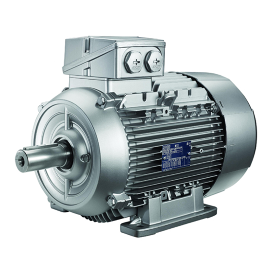
- Page 1 Installation and Maintance Manual 1LG0 low-voltage motor Answers for industry.
-
Page 2: Table Of Contents
Chapter 1.0 INTRODUCTION 1.1 Application Scope 1.2 Construction Type 2.0 HANDLING AND STORAGE 3.0 COMMISSIONING 3.1 Installation 3.2 Terminal Box 3.3 Balancing and Transmission Coupling 3.4 Electrical Connection 3.5 Insulation Resistance Inspection 3.6 Drive Application 4.0 MAINTANCE 4.1 Bearing Lifetime 4.2 Grease Type 4.3 Grease Lifetime and Regreasing Intervals 4.4 Regreasing Procedure... - Page 3 Special designs may vary in technical details. If in doubt, please contact the manufacturer, referencing the type designation and serial number (see rating plate), or have the installation, service and maintenance work executed by one of the SIEMENS Service Centers.
-
Page 4: Introduction
1LG0 Catalogue. 1.2 Motor construction and types 1LG0 motors are totally enclosed and self-ventilated (TEFC) by a bi-directional fan mounted on the NDE of the rotor shaft. Care must be taken to ensure adequate clearance for maximum air fl... -
Page 5: Handling And Storage
2.0 HANDLING AND STORAGE When lifting the motors, always use the lifting eyes provided. Prior to lifting the motor make sure that the lifting eyes are installed correctly and tightened. Never lift a motor using the rotor shaft and fan cowling. In addition care must be taken during lifting and lowering of the motor to avoid any shocks or vibrations which can result in bearing damages. -
Page 6: Commissioning
To ensure a quiet and vibration free operation, proper angular and radial alignment of a balanced transmission element (coupling, pulleys, fans, gear box, etc.) is essential. As standard, the 1LG0 rotors are dynamically balanced using a half feather key as indicated on the ratings name plate (H=Half Key). -
Page 7: Electrical Connection
3.4 Electrical connection All work must be carried out by skilled worker. Before starting any work, be sure to isolate the machine from the main and auxiliary power supply as applicable. Mains must be secured against accidental switch on. There are six power terminals and one earthing terminal located in the terminal box for FS80 to FS355. - Page 8 Star connection A star connection is obtained by connecting W2, U2, V2 terminals to each other and the U1, V1, W1 terminals to the mains. U2 (V2, W2) Delta connection A delta connection is obtained by connecting the end of a phase to the beginning of the next phase.
- Page 9 Protection 1LG0 motors have two types of electrical protection available as an option: • PTC - used for temperature alarming or tripping function • PT100 - used for alarming or tripping function Note : Both the PTC and PT100 require connection to an external control unit.
-
Page 10: Insulation Resistance Inspection
3.5 Insulation resistance inspection After extended periods of storage or standstill (6 months or longer), it is recommended to measure the insulation resistance between phases and phase to ground prior to applying power at start-up. During and shortly after the resistance measurement, the motor terminals Warning! Warning! are hazardous with a residual voltage charge. -
Page 11: Drive Application
3.6 Drive Application In applications when motor torque is variable (piston- type compressor, load for example), the inevitable result is a non-sinusoidal motor current, whose harmonics can lead to excessive system perturbation or excessive electromagnetic interference. Electromagnetic compatibility In application where the motor is driven by a drive, the degree of electrical interference depends on the type of drive used (type, number of IGBTs, interference suppression measures, and manufacturer), cabling, distance and application requirements. -
Page 12: Maintance
4.0 MAINTAINCE Safety precautions! Before starting any service and maintenance work on the motor the motor must be properly isolated from the mains and auxiliary power. The usual "5 safety rules" (as set forth in DIN VDE 0105) are: • Isolate the equipment •... -
Page 13: Grease Type
4.2 Grease type Type of grease: UNIREX N3 (Esso); Conforms to DIN 51825-K3N. Motors equipped with a regreasing device (K40 option) will have the grease information stamped on the rating plate or a sticker on the fan cowling. 4.3 Grease lifetime and regreasing intervals Motors from FS80 to FS160 are greased for life due to the fact sealed bearings is used. -
Page 14: Regreasing Procedure
4.4 Regreasing procedure All local safety regulations must be considered when regreasing the motor Warning! Warning! in operation or at a standstill. Care must be taken not to over grease the bearings as this can result in increased bearing temperatures. Dust and old grease must be prevented from entering the motor bearings during the regreasing cycles. -
Page 15: Bearing Replacement
4.5 Bearing replacement – assembly and disassembly As bearings near the end of their useful lifespan, the vibration and noise levels of the motor will increase considerably. If bearing inner daimeter or wear clearance is out of specifi cation as per table 4, the bearing must be replaced. -
Page 16: Drain Plug
4.6 Condensation drain plug On B3 construction types, the drain holes are located on the frame of the motor. Motors with drain holes are delivered from the factory with pre-installed plastic plugs. -
Page 17: Start Up
5.0 START UP Preliminary Inspection Before applying power to the motor for the fi rst time, it is recommended to check: 1) All retaining bolts are tightened including transmission coupling and alignment 2) Motor cooling fan unobstructed 3) Adequate bearing lubrication (grease) if equipped with regreasing nipples 4) Mains supply voltage and connection method match those of the rating nameplate for operation on DOL, Soft start, Drive 5) Proper connection of earthing (grounding) terminal... -
Page 18: Spare Parts
6.0 SPARE PARTS 1) IMB3 DE End Shield 2) IMB5 DE End Flange 3) Fan Cowling for all frame sizes 4) Bi-directional cooling fan for all frame sizes 5) Complete terminal box with out terminal board Spare part inquiry When enquiring about spares, it is necessary to provide the following information such as construction type, mounting arrangement, motor serial number and MLFB No. - Page 19 NOTE...
- Page 20 Siemens Ltd., China Subject to change without prior notice Industry Sector Siemens 09.2009 Drive Technologies...