
Related Manuals for Siemens Sentron SB TP01 Series


Summary of Contents for Siemens Sentron SB TP01 Series
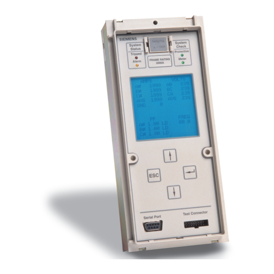
- Page 1 ™ Sentron Systems Breaker Energy Communicating Trip Unit Information and Instruction Guide Bulletin IPIM-2208B...
- Page 2 Siemens reserves the right to make changes at any time without notice or obligations. Should a conflict arise between the general information con- tained in this publication and the contents of drawings or supplementary material, or both, the latter shall take precedence.
-
Page 3: Table Of Contents
Remote Operation Alarm Setpoints Microsoft is a registered trademark, and Windows is a trademark of Microsoft Corporation. ACCESS, Isolated Multi-Drop, SEAbus, Sentron, and WinPM are trademarks of Siemens Energy & Automation, Inc. SIEMENS is a registered trademark of Siemens AG. - Page 4 The contents of the instruction manual shall not become part of or modify any prior or existing agreement, commitment or relationship. The sales contract contains the entire obligation of Siemens. The warranty contained in the contract between parties is the sole warranty of Siemens. Any...
-
Page 5: Introduction
(LEDs) MAX Rating Alarm Meter A standard feature on all Siemens trip units is RMS current sens- 2000 A ing. As opposed to peak-current sensing, RMS sensing measures the true heating potential of the current waveform. This allows for more accurate overcurrent protection and eliminates nuisance tripping due to harmonic distortion of the current waveform. - Page 6 Beyond the basic tripping function, the SB Energy-Comm trip unit Issuance of the tripping command from the microprocessor sends also collects real-time data that can be reported via the Siemens a signal from the trip unit to the low-energy, high-speed magnetic ACCESS System or directly to a personal computer through its latch in the circuit breaker.
-
Page 7: Sb Encased Systems Breaker
SB Encased Systems Breaker The interrupting rating of the SB breaker is specified on the front Siemens SB Encased Systems Breakers come in four (4) princi- cover label and is further identified by the use of a “color bar” at pal frame sizes with MAX Ratings ranging from 400 to 5000 the top left of the breaker label. -
Page 8: Front Panel Interface
Introduction Table 1.2 UL 489 Symmetrical RMS Amperes Interrupting Rating (kA) Optional Ratings and Application Voltage Breaker Frame Size 1200A 2000A 3200A 5000A Alternate A.I.R. (kA): Blue Label “SBA” @ 240V AC @ 480V AC @ 600V AC Standard A.I.R. (kA): Black Label “SBS” @ 240V AC @ 480V AC @ 600V AC... -
Page 9: Overcurrent Protective Functions
Introduction Alarm Setpoints The SB Energy-Comm trip unit’s full-featured model offers the ten alarm functions listed below: Rating Plug System System = 1600 A Status Check • Overcurrent Tripped Protective Indicators MAX Rating Alarm Meter 2000 A • Ground Overcurrent •... -
Page 10: Metering Functions
Introduction alarm activity, while the trip log stores tripping information. All pro- Features By Model Number tective relay settings are stored in nonvolatile memory. Table 1.4 summarizes the features available with each of the four trip unit models. The full-featured models (SBxxTP02 and Metering Functions SBxxTP02G) offer more alarm functions;... -
Page 11: Logs
Introduction 1.10 Logs 1.11 Communications The SB Energy-Comm trip unit maintains three logs: a trip log in 1.11.1 ACCESS Communications nonvolatile memory to document up to five of the most recent The EIA-485 communications port is located on the back of the trips, an event log to document up to ten of the most recent SB Energy-Comm trip unit. -
Page 12: Installation
PT module. Panel- on setting these parameters are listed in Section 5, Over- boards manufactured by Siemens are shipped with all required current Protection Configuration. wiring. Retrofit applications require a retrofit kit, which includes instructions for mounting and wiring the power supply and PT These are the minimum configuration requirements before... - Page 13 Installation Figure 2.1 SB Energy-Comm Wiring to External Power Supply, PT Module, and ACCESS System...
-
Page 14: Installing The Trip Unit In A Systems Breaker
Make certain that the breaker has the spring discharged and contacts open. The Siemens SB circuit breaker has a built-in interlock device that prevents the circuit breaker from being closed when there is not an installed trip unit. This same interlock device trips the circuit breaker when the trip unit is removed. - Page 15 For use with Types SB Circuit Breakers Frame Rating Listed Circuit Breaker Trip Unit Issue No. G-1126 Siemens Energy & Automation, Inc. Bellefountaine, OH 43311 Mate the connector half on the back of the trip unit with its cor- Before attempting to install the trip unit, check the label on the responding connector half in the circuit breaker.
- Page 16 Installation Lower the trip unit onto the support plate. Secure the trip unit. Secure the trip unit in place with the retaining screw located at the top of the device. Torque 6 to 8 in-lbs. If the trip unit top is not secured correctly the interlock will stop the breaker from closing.
-
Page 17: Inserting And Removing The Rating Plug
Installation Note: Before energizing the breaker, install a proper rat- Check the label on the rating plug. ing plug. Refer to Section 2.7, Inserting and Removing the Rating Plug. Note: Take care not to pinch any wires when replacing the front cover of the breaker. - Page 18 Installation Gently pry one end of the cover loose with a small screw- Conversely, to remove a rating plug, squeeze the clips, driver, and lift. Then remove the plexiglass shield. located on the sides of the plug, and pull the plug from the plug receptacle.
-
Page 19: Communications
Installation Seal the cover as needed with a lead seal for tamper evi- dent protection. Make sure that the circuit breaker is in the open position. Refer to the breaker’s information and instruction guide for the proper operating procedure. Spring Charged Contacts Closed Spring Discharged Contacts Open... -
Page 20: Starting Up
Installation Remove the trip unit retaining screw. 2.10 Starting Up Remove the screws from the seals to access the display interface keypad. The screws are on both sides of the display shield as shown below. Rating Plug System System = 1600 A Status Check Tripped... -
Page 21: User Interface
User Interface 3 User Interface end the scrolling of these screens, press Escape and the previously selected menu appears. Front Panel Display Front Panel Keys The integral front panel keypad and display of the SB Energy- The front panel provides the user with a keypad with four keys Comm trip unit provide the user with direct access to device for easy touch-control interface. -
Page 22: Menu Structure
User Interface Parameter Setting Screens Menu Structure Besides menus, the front panel display also shows settings The user interface displays provide the functions and status that can be changed by pressing the keys on the front panel. information. They are organized in a menu structure with the Several actions are available for parameter setting screens. -
Page 23: Front Panel Leds
User Interface The Metering menu shows the types of metered data and con- The Operations menu is used for troubleshooting and for figuration settings for demand values. It also includes the reviewing the history of the breaker. It shows a list of tests and screen for resetting the meter data. -
Page 24: Idle Display Mode
User Interface The Protective LED indicates the operation of the protective functions of the trip unit and blinks when operating properly. This LED operates at current levels over 20% of the rated load without external power, and at all current levels with external power. -
Page 25: System Configuration
System Configuration 4 System Configuration • Phase Sequence • Potential Transformer (PT) Rating Viewing System Configuration • Short Circuit Protection The System Configuration function allows you to set up the device to match the line frequency, phase sequence, and • External Neutral Sensing (Neutral CT) breaker connection settings of your system. - Page 26 System Configuration The SEQUENCE CONFIG screen will open with both the posi- Potential Transformer Rating tive and negative sequence boxes highlighted. When the Up To inform the trip unit which potential transformer (PT) is used key is pressed, positive sequence is selected (checked). in your system, select PT Rating from the System Configura- When the Down key is pressed, negative sequence is...
-
Page 27: Setting Other Device Parameters
System Configuration To set the pickup and time delay values for short time pro- When you have completed the time settings, the first tection and the pickup value for instantaneous protection, value, month (MM), in the date settings will be high- refer to the sections 5.4, Short Time Fault Protection, lighted. -
Page 28: Overcurrent Protection Configuration
Overcurrent Protection Configuration 5 Overcurrent Protection 10000 Configuration Long Time Pickup Protective Functions Menu The SB Energy-Comm trip unit provides configurable overcur- 1000 rent protection functions that can trip the SB circuit breaker. The user can easily accommodate load changes and other protection requirements while still assuring optimum coordina- tion. -
Page 29: Viewing Settings
Overcurrent Protection Configuration Viewing Settings 10000 To check the protection settings from the Protective Menu , select View Settings . The screen lists the values for the long time, short time, ground fault and instantaneous protection. 1000 Long Time Current (Amperes) To set these values for the long time fault protection, from the The abbreviations used in the screen are: Protective Menu select Long Time and press Enter... -
Page 30: Short Time Fault Protection
Overcurrent Protection Configuration Short Time Fault Protection The short time delay setting is used to set the time interval the breaker will wait before initiating a trip command at the current The short time setting establishes the maximum current level at value selected on the short time pickup setting. -
Page 31: Instantaneous Fault Protection
Overcurrent Protection Configuration Instantaneous Fault Protection The instantaneous pickup sets the level of high current at which the trip unit will trip the circuit breaker without a time delay. Non-delayed tripping, in response to a severe overcur- rent condition, minimizes potential damage to electrical sys- tems and equipment. -
Page 32: Ground Fault Sensing Scheme
Overcurrent Protection Configuration To set the mode, press Enter until the I T and the FIXED Neutural checkbox is highlighted. Press the Up or Down Arrow Main Disconnect key so that a check appears in the desired selection box. Link Source Neutral Trip... -
Page 33: Alarm Setpoints
Alarm Setpoints 6 Alarm Setpoints Each alarm limit has three parameters: • Pickup value Alarms • Delay value The SB Breaker has an optional relay output contact for con- trolling audible or visible alarms. The trip unit can be config- •... -
Page 34: Overcurrent
Alarm Setpoints Overcurrent Ground Overcurrent To alarm on overcurrent: The Ground Overcurrent alarm provides a preset ground fault indication, similar in function to the Ground Fault Monitor (SB- From the Alarms Menu , select Over Current. GFM) accessory module for the standard SB trip unit. Note that this ground overcurrent alarm feature is available on all SB Energy-Comm trip units with or without ground fault protection and is independent of the ground overcurrent tripping function. -
Page 35: Overcurrent Demand
Alarm Setpoints Overcurrent Demand Total Harmonic Distortion To alarm on demand overcurrent: To alarm on total harmonic distortion: From the Alarms Menu , select Over-Amp Demand. From the Alarms Menu , select Total Harmonics. Select a pickup value by pressing the Up or Down Select a pickup value by pressing the Up or Down... -
Page 36: Over Real Power
Alarm Setpoints Over Real Power Over Power Demand To alarm on over real power (kilowatts): To alarm on over power (kilowatt) demand: From the Alarms Menu , select Over kW. From the Alarms Menu , select Over kW Demand Select a pickup value by pressing the Up or Down Select a pickup value by pressing the Up or Down... -
Page 37: Over Reactive Power
Alarm Setpoints Over Reactive Power Over Apparent Power To alarm on over reactive power (kilovolt-amps reactive): To alarm on over apparent power (kilovolt-amps): From the Alarms Menu , select Over kVAR. From the Alarms Menu , select Over kVA Select a pickup value by pressing the Up or Down Select a pickup value by pressing the Up or Down... -
Page 38: Under Pf Lagging
Alarm Setpoints 6.10 Under PF Lagging 6.11 Over PF Leading To alarm on under power factor lagging: To alarm on over power factor leading: From the Alarms Menu , select Under PF Lagging. From the Alarms Menu , select Over PF Leading Select a pickup value by pressing the Up or Down Select a pickup value by pressing the Up... -
Page 39: Extended Protective Relaying
Extended Protective Relaying 7 Extended Protective Relaying Overview The SB Energy-Comm trip unit offers several protective relay- ing functions beyond the standard trip unit functionality. These extended functions include types of current, voltage, and fre- quency protection usually associated with a protective relay. •... -
Page 40: Neutral Overcurrent
Extended Protective Relaying Neutral Overcurrent Current Unbalance If an external neutral sensor has been selected during configu- Current unbalance is a protective relay function that protects ration, the allowable overcurrent on the neutral line can be set against an unbalance in the phase currents. Each phase cur- using the parameters from the Neutral Over Current selection rent is compared to the arithmetic average of the three phase of the Protective Relays Menu. -
Page 41: Undervoltage
Extended Protective Relaying Undervoltage Voltage Unbalance If the amount of voltage on any phase goes below a specified Voltage unbalance is a protective relay function that protects level, the trip unit can alarm or trip by setting the parameters against an unbalance in the line to line voltages. Each line-to- from the Undervoltage selection of the Protective Relays line voltage is compared to the arithmetic average of the three Menu. -
Page 42: Overvoltage
Extended Protective Relaying Overvoltage Reverse Power If the amount of voltage on any phase goes above a specified If the amount of reverse power goes above a specified level, level, the trip unit can alarm or trip by setting the parameters the trip unit can alarm or trip by setting the parameters from the from the Over Voltage selection of the Protective Relays Reverse Power selection of the Protective Relays Menu . -
Page 43: Over Frequency
Extended Protective Relaying Over Frequency 7.10 Under Frequency The trip unit can alarm or trip on the frequency of the monitored The trip unit can alarm or trip on the frequency of the monitored power by setting the parameters from the Over Frequency power by setting the parameters from the Under Frequency selection of the Protective Relays Menu . -
Page 44: Metering
Metering 8 Metering System Check Overview Protective The SB Energy-Comm trip unit measures and communicates Metering real-time and accumulated metering data as well as harmonics and waveform data. Current level values are derived from cur- rent transformers (CTs) mounted in the circuit breaker. These values can be viewed on the front panel display or viewed on a To access the metering functions and data, from the Main personal computer when it is connected properly to the trip... - Page 45 Metering From the Metering Menu, select Metered Data and select the first choice, V,A,PF, and Freq. +kVAR (Reactive Power) The following screen appears: Ø=90º -kW (Reverse) +kW (Forward) PF=0 +kVAR (Forward) +kVAR (Forward) -PF (Leading) +PF (Lagging) Ø +kW (Real Power) Ø=180º...
-
Page 46: Demand Configuration
Metering Demand Configuration Demand is calculated by summing the three-phase average current or the total watts over the interval, after which a new value is calculated. At the end of the interval the sum is divided 8.3.1 Viewing Demand Data by the number of samples. -
Page 47: Metered Data Waveforms
Metering As the following example shows, the Current Data selection displays three phases and the neutral line. The percentage for each odd harmonic is shown (from the 3rd to the 19th) along with the total harmonic distortion (THD). An example of the Current Graph selection is shown below. In this screen, the harmonic data shows that the current in phase A has some distortion due to the presence of the 5th and 7th harmonic. -
Page 48: Phase Balance
The following screen is displayed: Viewing the waveforms remotely from a personal computer requires the Siemens WinPM or SB Win software. This software can be used to upload waveform data from the trip unit to a personal computer and display the waveforms on the com- puter screen. -
Page 49: Reset Meter Data
Metering The voltage balance data shows the voltage in Volts for each Choose Energy Registers to reset the real-time (energy) values. phase and the percentage balance (ratio of the indicated phase voltage to the average of all three phases). Use the Up Arrow to move from No to Yes and the Down Arrow to move from Yes to No. -
Page 50: Logs
Logs 9 Logs The following is an example of an event log screen: Data logging can be extremely useful to study growth patterns, to schedule loads and cost allocation, to isolate problem sources, or to analyze a variety of power system operating conditions. The SB Energy-Comm trip unit supports three types of data logs: •... -
Page 51: Min/Max Log
Logs To view the trips, from the Log Menu, select View Trip Log. The trip unit Min/Max Log can be used to determine such val- ues as the highest loading on a plant or feeder, peak demand, The most recent trip displays as follows: voltage operating ranges, worst case power factor, highest VAR loading for capacitor sizing, etc. - Page 52 Logs recorded. An example of data with both minimum and maximum The maximum values for power are given for both forward and values is the voltage data. reverse power: To view the max/min voltage data, select Volts from the Min/ Max Data Menu.
-
Page 53: Communications
Baud Rate from the Communications Menu. The following pendent of the transfer rate setting for the EIA-485 port. screen appears: The SB Energy-Comm trip unit is fully compatible with Siemens supervisory software that can display all measured parameters and status information, waveform data, and data logs provided by the trip unit. -
Page 54: Setting The Address And Baud Rate
Communications All information transferred between the master and slave To configure the device address, select Slave Address form devices is sent within a SEAbus protocol message packet. the Communications Menu. The following screen appears: SEAbus is a byte-count oriented open protocol originally devel- oped for ACCESS communications between the devices. -
Page 55: Supervisory Software
Windows applications. Your computer running WinPM software can be connected to intelligent field devices via a Siemens Isolated Multi-Drop Con- verter or through a modem and a Siemens Isolated Multi-Drop Converter to the ACCESS system’s SEAbus communications bus. -
Page 56: Operations Menu Functions
Operations Menu Functions 11 Operations Menu Functions Take precautions to prevent damage to equip- ment protected by the breaker prior to perform- ing the tests. 11.1 Overview To run a breaker test, select Operations from the Main Menu . The Operations Menu contains testing options and breaker Then select Breaker Test . -
Page 57: Mechanical Counter
MAX RATING value. To view the Interruption Level counter, select Interruption Level from the Operations Menu. The following screen appears: If the message “Test Failed” appears, contact Siemens cus- tomer service for assistance Press Escape to return to the Operations Menu. -
Page 58: Security
Security 12 Security 12.2 Enable Security With the security enabled, the user cannot change any of the 12.1 Overview settings without first entering the password. If the operator attempts to change a setting such as the protective relay or To prevent inadvertent changes to the configuration of the trip alarms, and then presses Escape to leave the particular unit, the SB Energy-Comm trip unit has password protection. -
Page 59: Change Password
The trip unit will prompt you to re-enter your new password. appears: Repeat steps 2 and 3. Contact Siemens customer service if you have forgotten the password. Select Change Password. The Change Password screen lets you enter a new password one digit at a time. -
Page 60: Testing
The following startup message appears: Type in one of the following letters, depending upon the test you wish to perform: Siemens Energy & Automation, Inc. TS-31 Test Set. Press ENTER to continue “L” - Long time or overload test,... -
Page 61: Error Messages
Testing If you pressed the letter “A” to abort, you will be asked again: 10. If you DON’T wish to change a setting, just press ENTER. If you DO wish to change a setting, type in the new setting Enter Test to perform and press ENTER. - Page 62 Testing This message will appear if you enter a setting value that does not exist. For example, if the trip unit has continuous current settings of 50, 60, 65, 70, 75, 80, 85, 90, 95, and 100 percent, and you enter any other value than those listed, the above message will appear.
-
Page 63: Functions And Outputs
Functions and Outputs Function Alarm Trip Event Log Trip Log Overcurrent (Alarm) Ground Overcurrent Overcurrent Demand Total Harmonics (THD) Alarm Over kW Setpoints Over kW Demand (10) Over kVAR Over kVA Under PF Lag Over PF Lead Long Time Overcurrent Short Time Protection Instantaneous... -
Page 64: Time Current Characteristic Curves
Time Current Characteristic Curves Amperes in Multiples of Rating Plug Value (I Amperes in Multiples of Rating Plug Value (I (1) Continuous Ampere Setting Region (1) Continuous Ampere Setting Region 10,000 The allowable continuous operating amperes is set to a percentage of The allowable continuous operating amperes is set to a percentage of the rating plug value. - Page 65 Time Current Characteristic Curves Amperes in Multiples of Rating Plug Value (I 10,000 Continuous Amps set at 70% of I 1000 Long Time Delay set at 25 sec., cali- brated at 6 times I = %(Max Rating) Short Time Pickup set at 2.5 times I 1000 Ground Fault Pickup...
- Page 66 Time Current Characteristic Curves 10,000 Continuous Operating Current 1000 Long Delay 0.01 Long Time Overcurrent Protection (curves and parameter screen) 10,000 Continuous Operating Current 1000 Long Time Delay Short Time Pickup Short Time Fixed Delay 0.01 Long Time and Short Time (Fixed) Overcurrent Protection (curves and parameter screens)
- Page 67 Time Current Characteristic Curves 10,000 Continuous Operating Current 1000 Long Time Delay Short Time Pickup Short Time t Delay 0.01 Long Time and Short Time (I2t) Overcurrent Protection (curves and parameter screens) 10,000 Continuous Operating Current 1000 Long Time Delay Instantaneous Pickup 0.01...
- Page 68 Time Current Characteristic Curves 10,000 Continuous Operating Current 1000 Long Time Delay Short Time Pickup Short Time Fixed Delay Instantaneous Override 0.01 Long Time, Short Time (Fixed), and Instantaneous Protection (curves and parameter screens)
- Page 69 Time Current Characteristic Curves Ground Fault Pickup Ground Fault Fixed Delay 0.01 Ground Fault Pickup Ground Fault t Delay 0.01 Ground Fault Protection (curves and parameter screens for units with Ground Fault Protection)
-
Page 70: Parameter Settings
Parameter Settings Long Time Protection Settings 100% = Rating Plug (A) Pickup (A) 1000 1000 1200 1020 1080 1140 1200 1600 1040 1120 1200 1280 1360 1440 1520 1600 2000 1000 1200 1300 1400 1500 1600 1700 1800 1900 2000 2500 1250 1500... - Page 71 Parameter Settings Short Time Protection Settings 150% 200% 250% 300% 350% 400% 500% 600% 700% 800% 900% = Rating Max Rating Pickup (A) Plug (A) 1000 1200 1400 1600 1800 1125 1350 1575 1800 2025 1000 1250 1500 1750 2000 2250 1200 1500...
- Page 72 Parameter Settings Instantaneous Protection Settings 150% 200% 300% 400% 500% 600% 700% 800% 900% 1000% 1200% = Rating Plug Max Rating Pickup (A) 1000 1200 1400 1600 2000 2400 1125 1350 1575 1800 2250 2700 1000 1250 1500 1750 2000 2500 3000 1200...
- Page 73 Parameter Settings Overcurrent Alarm Settings 115% 125% 150% 200% 250% = Rating Pickup (A) Plug (A) 1000 1125 1000 1250 1200 1500 1050 1400 1750 1000 1200 1600 2000 1000 1150 1250 1500 2000 2500 1200 1380 1500 1800 2400 3000 1600 1840...
- Page 74 Parameter Settings Neutral Overcurrent Relay Settings % Max Rating 115% 125% 150% 200% 250% Max Rating Pickup (A) 1000 1000 1200 1600 2000 1200 1380 1500 1800 2400 3000 1600 1840 2000 2400 3200 4000 2000 2300 2500 3000 4000 5000 2500 2875...
- Page 75 Parameter Settings Current Unbalance Relay Settings = Rating Plug (A) Pickup (A) 1000 1200 1600 2000 1000 2500 1000 1250 3000 1200 1500 3200 1280 1600 4000 1200 1600 2000 1000 1500 2000 2500 5000 Alarm Delay Settings Time (s) Voltage Unbalance Alarm Settings % of Rating PT (V)
- Page 76 Parameter Settings Undervoltage Alarm Settings % of PT Rating PT Rating (V) Pickup (V) Overvoltage Alarm Settings % of PT Rating 105% 110% 115% 120% 125% PT Rating (V) Pickup (V) Miscellaneous Pickup Settings Overfrequency (Hz) Underfrequency (Hz) Total Harmonic Distortion (%) Over Power Factor 0.50 0.60...
- Page 77 Parameter Settings Max Rating (A) Over kVA (kW) 1200 1050 1125 1200 1275 1600 1000 1100 1200 1300 1400 1500 1600 1700 1000 2000 1125 1250 1375 1500 1625 1750 1875 2000 2125 1100 1250 2500 1400 1550 1700 1875 2050 2200 2350...
-
Page 78: Menu Structure
Menu Structure Front Panel Men Structure... -
Page 79: Seabus Plus Packet
SEAbus Plus Packet SEAbus Plus Packet Message Type (Msgt) Byte The message type byte, Msgt, identifies the particular mes- Both SEAbus and SEAbus Plus use a simple byte-count sage being sent. This, in turn, determines the length and type approach to realize communications between a master and its of data (if any) to follow in the Data field of the SEAbus Plus slave devices. -
Page 80: Glossary
ACCESS system A power monitoring and control system by numbers range from 00000 to 99999. Siemens. The SB Energy-Comm trip unit is one of several ACCESS system field devices that can communicate with a per- sonal computer or other supervisory device. - Page 81 Glossary demand The measurement and summation of current or energy frame size See Breaker Frame Size. over a specified time, typically 15 or 30 minutes. demand period The specified time, typically 15 or 30 minutes, over which current or energy data is collected and from which the GF ground fault (protection).
- Page 82 Glossary over amp demand alarm The alarm signal from the trip unit when the system exceeds a specified current demand setting. logs Tables in the trip unit’s memory to store trip information, event information, and metered value minimum/maximum values. overcurrent alarm The alarm signal from the trip unit when the system exceeds a user-specified current setting.
- Page 83 SEAbus The protocol used by the SB Energy-Comm trip unit TS-31 See Portable Test Set. and other Siemens ACCESS field devices. Transmit signal (communications). Security menu The menu selection, available from the Main menu, that allows the operator to choose the password and enable security.
- Page 84 Glossary under frequency alarm The alarm signal from the trip unit when the system drops below a user-specified line frequency value. voltage balance See Phase Balance. VT Voltage transformer. See PT. W, X, Y waveform The graphical depiction of the current or voltage over time.
-
Page 85: Index
Index Index over-amp demand option 31 pf lagging 34 pf leading 34 total harmonics option 31 ACCESS Baud Rate 76 ACCESS Baud Rate Menu Option 50 ACCESS Bus Master 7 Baud Rate 50 device changes 7 changing 50 device information 7 setting 50 local operation 7 Breaker See Circuit Breaker... - Page 86 Index remote open option 51 RS232 baud rate option 49 Fault Counter 53, 77 slave address option 50 Fault Counter Menu Option 53 view comm config option 49 Faults 53 Compatibility with Supervisory Software 49 by type of protection 53 Counters 76 defined 77 fault 53...
- Page 87 Index event log 6, 46 min/max log 7, 47 Harmonics 42 trip log 6, 46 calculations 42 Long Time and Instantaneous Overcurrent Protection Time current data 43 Characteristics Curve 63 current graphs 43 Long Time and Short Time (Fixed) Overcurrent Protection defined 77 Time Characteristic Curve 62 Long Time and Short Time (I2t) Overcurrent Protection Time...
- Page 88 Index parameters 40 Over Reactive Power Condition 33 power flow conventions 41 Over Real Power Condition 32 power polarity conventions 41 Over Voltage 78 reset meter data 45 Over-Amp Demand Menu Option 31 summary of features 40 Overcurrent Alarm 78 viewing calculated values 41 settings 69 viewing demand data 42...
- Page 89 Index Pickup Settings 72 Over Power Factor 72 Rating Plugs 13 overfrequency 72 and ampere ratings 13 total harmonic distortion 72 and pick-up values 13 Under Power Factor 72 available ampere values 13 underfrequency 72 installing 13 Potential Transformer Module See PT Module removing 14 Power Factor 78 Real-time Energy Values 45...
- Page 90 Index longitudinal redundancy check (lrc) byte 75 view config menu 21 message type (msgt) byte 75 viewing 21 synchronization (sync) byte 75 System Configuration Menu 18, 21 specifications 75 System Configuration Parameters 21 Security Inactive Screen 24 external neutral sensor (neutral CT) 21 Security Menu 19, 54 potential transformer (PT) rating 21 change password option 54, 55...
- Page 91 Index Under Frequency 39 Waveform Capture 80 defined 80 Waveform Graphs 44 Under Power Factor (Lagging) Condition 34 defined 80 Under Power Factor Pickup Settings 72 WinPM Software 51, 80 Under Voltage Wiring 9 defined 79 accessories 9 Underfrequency Pickup Settings 72 connecting to an ACCESS Host device 9 Undervoltage 37 illustration of connections 9...
- Page 92 Distribution Products Division www.sea.siemens.com/ 3333 Old Milton Parkway sales/salesoffices.html Alpharetta, GA 30005 ©Siemens Energy & Automation, Inc. Bulletin IPIM-2208B Siemens is a registered trademark of Siemens AG (Supercedes 4.5-2.A) Specifications are subject to change without notice. 2.5M1299SP Printed in U.S.A.