HP 8920A Application Handbook
Rf communications test set
Hide thumbs
Also See for 8920A:
- User manual (659 pages) ,
- Application handbook (319 pages) ,
- Programmer's manual (607 pages)
Table of Contents
Advertisement
Quick Links
Advertisement
Chapters
Table of Contents

Related Manuals for HP 8920A


Summary of Contents for HP 8920A
- Page 1 sales@artisantg.com artisantg.com (217) 352-9330 | Click HERE Find the Keysight / Agilent 8920B at our website:...
- Page 2 Agilent Test & Measurement website, www.tm.agilent.com. HP References in this Manual This manual may contain references to HP or Hewlett-Packard. Please note that Hewlett-Packard's former test and measurement, semiconductor products and chemical analysis businesses are now part of Agilent Technologies. We have made no changes to this manual copy.
- Page 3 HP 8920A & HP 8920B RF Communications Test Set, Application Handbook SCREEN CONTROL INSTRUMENT STATE MSSG HELP CONFI HOLD PRINT ADRS SAVE MEAS DUPLE PREV TESTS LOCAL RECAL PRESE USER DATA FUNCTIONS DATA k1’ METER INCR INCR INCR ENTER k2’...
- Page 4 Copyright © Hewlett-Packard Company 1994 Notice Information contained in this document is subject to change without no- tice. All Rights Reserved. Reproduction, adaptation, or translation without prior written permission is prohibited, except as allowed under the copy- right laws. This material may be reproduced by or for the U.S. Government pursu- ant to the Copyright License under the clause at DFARS 52.227-7013 (APR 1988).
- Page 5 Manufacturer’s This statement is provided to comply with the requirements of Declaration the German Sound Emission Directive, from 18 January 1991. This product has a sound pressure emission (at the operator position) < 70 dB(A). Sound Pressure Lp < 70 dB(A). •...
- Page 6 Safety GENERAL Considerations This product and related documentation must be reviewed for familiar- ization with safety markings and instructions before operation. This product is a Safety Class I instrument (provided with a protective earth terminal). SAFETY EARTH GROUND A unterruptible safety earth ground must be provided from the main power source to the product input wiring terminals, power cord, or sup- plied power cord set.
- Page 7 CAUTION A CAUTION note denotes a hazard. It calls attentionto an operation procedure, practice, or the like, which, if not correctly performed or adhered to, could result in damage to or destruction of part or all of the product. Do not proceed beyond an CAUTION note until the indicated conditions are fully understood and met.
- Page 8 For warranty service or repair, this product must be returned to a service facility designated by HP. Buyer shall prepay shipping charges to HP and HP shall pay shipping charges, duties, and taxes for products re- turned to HP from another country.
- Page 9 NO OTHER WARRANTY IS EXPRESSED OR IMPLIED. HP SPE- CIFICALLY DISCLAIMS THE IMPLIED WARRANTIES OF MER- CHANTABILITY AND FITNESS FOR A PARTIDCULAR PURPOSE.
- Page 10 24001 E. Mission Ave. Liberty Lake, WA 99019-9599 Declares that the product(s): Product Name: RF Communications Test Set Model Number(s): HP 8920A, 8920B Product Options: Conforms to the following product specifications. Safety: HD 401/IEC 348 EMC: EN 55011 (1991) /CISPR 11 (1990): ‘Group 1,...
- Page 11 In this Book This book is a guide for performing common radio tests using the Test Set. This guide contains the following chapters and appendices. Chapter 1, Getting Started With The Test Set This chapter contains a description of the manual contents, a general description of the Test Set, and a general description of the front and rear panel controls, indicators, and connectors.
- Page 12 This chapter lists any manuals, application notes, specifications, and standards referenced in this guide. Chapter 10, HP 8920A Specifications This chapter provides abbreviated specifications for the HP 8920A. Chapter 11, HP 8920B Specifications This chapter provides abbreviated specifications for the HP 8920B.
- Page 13 Contents 1 Getting Started With The Test Set Conventions Used In This Manual 24 Product Description 25 The Test Set’s Features 28 Artisan Technology Group - Quality Instrumentation ... Guaranteed | (888) 88-SOURCE | www.artisantg.com...
- Page 14 Contents 2 Measurements Considerations Measurement Guideline 1 44 Measurement Guideline 2 45 Measurement Guideline 3 46 Measurement Guideline 4 48 Artisan Technology Group - Quality Instrumentation ... Guaranteed | (888) 88-SOURCE | www.artisantg.com...
- Page 15 Contents 3 Testing FM Radios Introduction 50 List of Tests 51 FM Transmitters 52 FM Receivers 79 Artisan Technology Group - Quality Instrumentation ... Guaranteed | (888) 88-SOURCE | www.artisantg.com...
- Page 16 Contents 4 Testing AM Radios Introduction 116 List of Tests 117 AM Transmitters 118 AM Receivers 136 Artisan Technology Group - Quality Instrumentation ... Guaranteed | (888) 88-SOURCE | www.artisantg.com...
- Page 17 Contents 5 Testing SSB Radios Introduction 160 List of Tests 161 SSB Transmitters 162 SSB Receivers 173 Artisan Technology Group - Quality Instrumentation ... Guaranteed | (888) 88-SOURCE | www.artisantg.com...
- Page 18 Contents 6 Spectrum Analyzer Measurements Introduction 188 List of Measurements 189 Using the Spectrum Analyzer 190 Using the Tracking Generator 205 Artisan Technology Group - Quality Instrumentation ... Guaranteed | (888) 88-SOURCE | www.artisantg.com...
- Page 19 Contents 7 Oscilloscope Measurements Introduction 234 Using the Oscilloscope 235 Artisan Technology Group - Quality Instrumentation ... Guaranteed | (888) 88-SOURCE | www.artisantg.com...
- Page 20 Contents 8 Configuring for Measurements Preparing the Test Set for DC Operation 244 Artisan Technology Group - Quality Instrumentation ... Guaranteed | (888) 88-SOURCE | www.artisantg.com...
- Page 21 Contents 9 References Manuals 250 Application Note 251 Specifications and Standards 252 Artisan Technology Group - Quality Instrumentation ... Guaranteed | (888) 88-SOURCE | www.artisantg.com...
-
Page 22: Table Of Contents
Contents 10 HP 8920A Specifications Signal Generator Specifications 255 Audio Source Specifications 261 RF Analyzer Specifications 262 AF Analyzer Specifications 268 Oscilloscope Specifications 271 Spectrum Analyzer Specifications (Option 102) 272 Signaling (Option 004) 276 DC Current Meter (Option 103) 277... - Page 23 Contents 11 HP 8920B Specifications Signal Generator Specifications 285 Audio Source Specifications 291 RF Analyzer Specifications 292 AF Analyzer Specifications 297 Oscilloscope Specifications 300 Spectrum Analyzer Specifications (Option 102) 301 Signaling (Option 004) 304 DC Current Meter 305 Remote Programming 306...
- Page 24 Contents Artisan Technology Group - Quality Instrumentation ... Guaranteed | (888) 88-SOURCE | www.artisantg.com...
- Page 25 Getting Started With The Test Set This chapter provides the user with a general introduction to the instrument. Information provided includes a general description of the Test Set, and a general description of the front and rear panel features. Artisan Technology Group - Quality Instrumentation ... Guaranteed | (888) 88-SOURCE | www.artisantg.com...
- Page 26 Conventions Used In This Manual Conventions Used In This Manual The Test Set keys, screen titles, fields, and shifted functions are shown using the following conventions: (Refer to the RX TEST screen and the instrument front panel.) Screen titles are shown in bold upper-case type −RX TEST •...
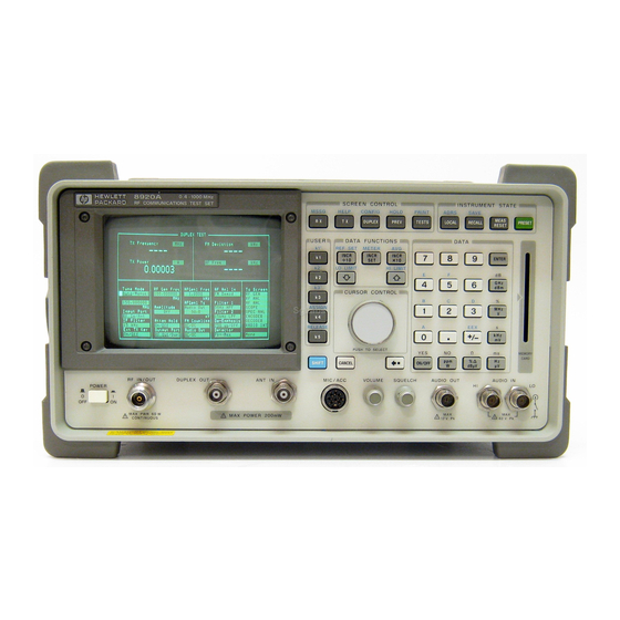
- Page 27 Product Description Product Description The Test Set is a single instrument that combines the features of 22 individual radio test instruments. The Test Set is designed to meet the communication test needs of both service and manufacturing environments, and the capability to test land mobile radios, cellular phones, and various other communications systems.
- Page 28 Synthesized AM/FM signal generator to 1000 MHz • Function generator (HP 8920A option) • AM/FM modulation analyzer • Duplex offset generator • Signalling encoder and decoder (HP 8920A option) • SSB demodulator • RF power meter • RF frequency counter/frequency error meter •...
- Page 29 Specifications" on page 253 "HP 8920B Specifications" on page 283 See the HP 8920A /B RF Communications Test Set Assembly Level Repair Guide for a complete list of specifications. Artisan Technology Group - Quality Instrumentation ... Guaranteed | (888) 88-SOURCE | www.artisantg.com...
- Page 30 The Test Set’s Features The Test Set’s Features This section contains a brief description of the Test Set’s keys, connectors, controls, and screens. Additional operating information for all keys, connectors, controls, and screens can be found in the Test Set’s user guide. Feature Contents "The Test’s Sets Front-Panel Features"...
- Page 31 The Test Set’s Features The Test’s Sets Front-Panel Features SCREEN CONTROL INSTRUMENT STATE MSSG HELP CONFIG HOLD PRINT ADRS SAVE MEAS DUPLEX PREV TESTS LOCAL RECALL PRESET RESET USER DATA FUNCTIONS DATA k1’ REF SET METER INCR INCR INCR X10 ENTER : 10 k2’...
- Page 32 Configure − used to control the various functions including date, screen • intensity, various RF controls, etc. I/OConfigure − used to control the various functions including HP-IB, • serial parameter, etc. Print Configure − used to setup a printer.
- Page 33 The Test Set’s Features Screens that Require an Option Spectrum Analyzer − used to display the spectrum analyzer measurement • function, with center frequency, span, reference level, marker, and tracking generator controls. Encoder − used to display the signalling encoder function, with function •...
- Page 34 The Test Set’s Features User Keys USER DATA FUNCTIONS REF SET METER INCR INCR INCR : 10 LO LIMIT HI LIMIT CURSOR CONTROL ASSIGN RELEASE PUSH TO SELECT ON/OFF SHIFT CANCEL − User k1 - k5 keys referred to as local keys, these keys enable you to instantly enable a field for fast or repetitive access.
- Page 35 The Test Set’s Features Data Function Keys USER DATA FUNCTIONS REF SET METER INCR INCR INCR : 10 LO LIMIT HI LIMIT CURSOR CONTROL ASSIGN RELEASE PUSH TO SELECT ON/OFF SHIFT CANCEL The INCR ÷ 10, INCR SET, and INCR X10 keys change the increment/ •...
- Page 36 The Test Set’s Features Knobs USER DATA FUNCTIONS REF SET METER INCR INCR INCR : 10 LO LIMIT HI LIMIT CURSOR CONTROL ASSIGN RELEASE PUSH TO SELECT ON/OFF SHIFT CANCEL MIC/ACC VOLUME SQUELCH ANT IN The Cursor Control Knob • Moves the cursor to another field (rotate CW/CCW).
-
Page 37: Screen Control Keys" On Page
The Test Set’s Features Screen Control Keys SCREEN CONTROL INSTRUMENT STATE MSSG HELP CONFIG HOLD PRINT ADRS SAVE MEAS DUPLEX PREV TESTS LOCAL RECALL RESET USER DATA FUNCTIONS DATA These keys are used to access several instrument control and information screens. RX key −... -
Page 38: Instrument State Keys" On Page
PRESET RESET USER DATA FUNCTIONS DATA LOCAL key − returns the instrument to manual control after HP- IB control • is used. RECALL key − lists and selects a previously stored instrument setup. • MEAS RESET key − clears the measurement “history” for all of the •... - Page 39 The Test Set’s Features Data Keys USER DATA FUNCTIONS DATA REF SET METER INCR INCR INCR ENTER : 10 LO LIMIT HI LIMIT CURSOR CONTROL ASSIGN RELEASE PUSH TO SELECT Ω ON/OFF SHIFT CANCEL µV dBµV MEMORY CARD − Data Entry keys used to enter or change alphanumeric data (0-9, A-F, −...
- Page 40 The Test Set’s Features Connectors ON/OFF SHIFT CANCEL µV dBµV M EMORY CARD MIC/ACC VOLUME SQUELCH AUDIO OUT AUDIO IN RF IN/OUT DUPLEX OUT ANT IN POWER MAX POWER 60 W MAX POWER 200 mW 12 v Pk 42 v Pk CONTINUOUS −...
-
Page 41: Non-Bracketed Keys And Memory Card Slot" On Page
The Test Set’s Features Non-Bracketed Keys and Memory Card Slot CURSOR CONTROL ASSIGN RELEASE PUSH TO SELECT Ω ON/OFF SHIFT CANCEL µV dBµV MEM ORY CARD MIC/ACC VOLUME SQUELCH AUDIO OUT AUDIO IN RF IN/OUT DUPLEX OUT ANT IN POWER Non-Bracketed Keys −... -
Page 42: The Test Set's Rear-Panel Features
TRIGGER HEADPHONE 5A 250V Connectors HP-IB Connector (optional) − 24-pin connector provides communication • between the Test Set and other instruments or a computer using the IEEE 488 Hewlett-Packard Interface Bus (HP-IB). SERIAL PORT Connector (optional) − 6-pin RJ-11 dual serial (RS-232C) •... -
Page 43: Key And Fuse Holders" On Page
The Test Set’s Features EXT SCOPE TRIGGER INPUT Connector − female BNC connector to • input an external oscilloscope trigger. Maximum input level is ≈ 20 V peak. 10 MHz REF OUTPUT Connector − female BNC connector outputs a 10 •... - Page 44 The Test Set’s Features Artisan Technology Group - Quality Instrumentation ... Guaranteed | (888) 88-SOURCE | www.artisantg.com...
- Page 45 Measurements Considerations The following guidelines must be adhered to when performing any of the FM/AM/SSB Transmitter and Receiver, Spectrum Analyzer, or Oscilloscope Measurements. Artisan Technology Group - Quality Instrumentation ... Guaranteed | (888) 88-SOURCE | www.artisantg.com...
- Page 46 Measurement Guideline 1 Measurement Guideline 1 Connector Considerations CAUTION: The RF present at any Test Set input connector must not exceed the specified level or permanent instrument damage may result. If necessary, use an external attenuator. If overpower occurs, disconnect the Transmitter, then cycle Test Set power OFF/ON to reset the protection circuitry.
- Page 47 Tracking Generator option (002) must be installed in the Test Set. Oscilloscope For Oscilloscope Measurements, Hewlett-Packard’s HP 104XX series passive Oscilloscope probes can be used to input signals to the Oscilloscope via the front panel Audio Input or rear panel MODULATION INPUT connectors.
- Page 48 Measurement Guideline 3 Measurement Guideline 3 Special Test Considerations Information for performing any of the FM, AM, or SSB measurements: Coaxial Cable Use short runs of high quality coaxial cable and high quality adapters when connecting the device connected to the Test Set to ensure the most accurate power measurement.
- Page 49 Measurement Guideline 3 internal speaker connection, either the Test Set AUDIO IN signal must be connected across the speaker (in this case, enter the impedance value of the speaker in lieu of the test load resistance), or the internal speaker must be physically disconnected. Measuring Audio Output Power When measuring audio output power in watts, always set Ext Load R field to the Receiver’s audio output impedance or to the test load...
- Page 50 Measurement Guideline 4 Measurement Guideline 4 Additional Measurement Considerations Pressing the PRESET and TX or RX keys at the beginning of each test automatically configures the Test Set for “standard” transmitter/ receiver measurements. The controls and settings that need to be adjusted during performance of the measurement are discussed in each procedure.
- Page 51 Testing FM Radios Artisan Technology Group - Quality Instrumentation ... Guaranteed | (888) 88-SOURCE | www.artisantg.com...
- Page 52 Introduction Introduction Each procedure may contain the following information: • A brief measurement overview and a reference to applicable TIA/EIA spec- ifications for each test. • A list of the Test Set options and additional test equipment required to per- form the procedure.
- Page 53 List of Tests List of Tests FM Transmitter Measurements "FM Off The Air Monitoring/Determining Unknown Transmitter Carrier Frequency" on page "FM Output Power, Deviation, and Frequency/Frequency Error Measurement" on page "FM Deviation and Symmetry Measurement" on page "FM Microphone Sensitivity and Modulation Limiting Measure- ment"...
- Page 54 FM Transmitters FM Transmitters The following measurements are provided for testing FM Transmitters. The procedures are arranged in the order that tests are typically per- formed. Artisan Technology Group - Quality Instrumentation ... Guaranteed | (888) 88-SOURCE | www.artisantg.com...
-
Page 55: Fm Off The Air Monitoring/Determining Unknown Transmitter
FM Transmitters FM Off The Air Monitoring/Determining Unknown Transmitter Carrier Fre- quency Description This procedure is used to locate, demodulate, and measure an FM signal’s output carrier frequency. The low level signal is input to the front-panel ANT IN connector, located, then demodulated using the spectrum analyzer function. - Page 56 FM Transmitters Spectrum Analyzer/Tracking Generator (option 102) Test Set Options Required Whip antenna Additional Equipment Required Measurement Procedure: 1 Connect the Antenna to the ANT IN connector. CAUTION: Do not exceed the connector’s rated input or permanent instrument damage may result. On the Test Set: 2 Press the PRESET key.
- Page 57 FM Transmitters Once the desired carrier is found: 7 From Controls, select Main. 8 Select Marker from the Choices field. 9 Use the Marker To field to select the desired carrier. On the Test Set frequency and level are displayed as shown. SPECTRUM ANALYZER BW= 3 kHz Marker...
-
Page 58: Fm Output Power, Deviation, And Frequency/Frequency Error
FM Transmitters FM Output Power, Deviation, and Frequency/Frequency Error Measurement Description This procedure is used to measure an FM Transmitter’s output carrier Ω power and frequency (or frequency error) into 50 . For FM Transmitters, deviation and modulating frequency are also measured. FM reference is ANSI/EIA-RS-152-C-1988, RS-316-C. - Page 59 FM Transmitters The typical error for the standard Test Set timebase is 2-3 Hz per 1 MHz (when measuring carrier frequency). If greater Test Set Options Required accuracy is required, use a Test with Option 001 (High Stability Timebase). "Cable and Adapter Loss" on page Special Test Considerations Measurement Procedure: 1 Connect the Transmitter Under Test as shown.
-
Page 60: Measurement
FM Transmitters 8. Determine if actual frequency readout or frequency error is the desired measurement. For actual frequency readout, continue with step 9 For frequency error: • Set Tune Mode to Manual. • Set Tune Freq to the expected carrier frequency. On the Radio: 9 Key the Transmitter. -
Page 61: Fm Deviation And Symmetry Measurement
FM Transmitters FM Deviation and Symmetry Measurement This procedure is used to measure an FM Transmitter’s frequency deviation and deviation symmetry. FM deviation is displayed on the Test Set. Deviation symmetry requires measuring the plus and minus peaks, then calculating symmetry. Knob Data Entry Keys... - Page 62 FM Transmitters Measurement Procedure: 1 Connect the Transmitter Under Test as shown. CAUTION: The RF present at the Test Set RF IN/OUT connector must not exceed 60W continuous (or 100 Watts for 10 sec/minute). On the Test Set: 2 Press the PRESET key. 3 Press the TX key.
- Page 63 FM Transmitters 9 Record the displayed FM Deviation as Pk+. Calculate the Measurement: 10 Calculate the Deviation Symmetry as follows: (Pk +) - (Pk -) Deviation Symmetry (in percent) = X 100 (Pk +) (3.010) - (2.971) For example, = X 100 = 1.29 (3.010 Artisan Technology Group - Quality Instrumentation ...
-
Page 64: Fm Microphone Sensitivity And Modulation Limiting Measure
FM Transmitters FM Microphone Sensitivity and Modulation Limiting Measurement Description This procedure is used to measure an FM Transmitter’s audio input sensitivity, and modulation limiting capability (if available). Modulation limiting is verified over the Transmitter’s audio frequency range. FM reference is ANSI/EIA-RS-152-C-1988 RS-316-B. Knob Data Entry Keys... - Page 65 FM Transmitters "Incidental Audio" on page Special Test Considerations Measurement Procedure: 1 Connect the Transmitter as shown. CAUTION: The RF present at the Test Set RF IN/OUT connector must not exceed 60W continuous (or 100 Watts for 10 sec/minute). On the Test Set: 2 Press the PRESET key.
- Page 66 FM Transmitters TX TEST TX Frequency FM Deviation 145.280024 2.965 TX Power AF Freq 2.03 1.00004 AFGen1 Freq To Screen Tune Mode Input Port AF Anl In 1.0000 RF GEN Auto/Manual RF in/Ant FM Demod RF ANL AF ANL Tune Freq AFGen1 Lvl IF Filter Filter 1...
-
Page 67: Fm Ctcss Encoder Frequency And Deviation Measurement" On
FM Transmitters FM CTCSS Encoder Frequency and Deviation Measurement Description This procedure is used to measure an FM Transmitter’s Continuous Tone Coded Squelch System (CTCSS) encoder frequency and frequency deviation. Both frequency and deviation are read directly off the Test Set screen. FM reference is ANSI/EIA RS-220-A. Knob Data Entry Keys... - Page 68 FM Transmitters Measurement Procedure: 1 Connect the Transmitter as shown. CAUTION: The RF present at the Test Set RF IN/OUT connector must not exceed 60W continuous (or 100 Watts for 10 sec/minute). On the Test Set: 2 Press the PRESET key. 3 Press the TX key.
-
Page 69: Fm Cdcss Coding And Deviation Measurements
FM Transmitters FM CDCSS Coding and Deviation Measurements Description This procedure is used to analyze an FM Transmitter’s Continuous Digital Coded Squelch System (CDCSS) digital data stream and frequency deviation. The data rate, binary data stream, and octal code are all displayed on the Test Set screen. Knob Data Entry Keys... - Page 70 FM Transmitters Decoder Option Test Set Options Required Measurement Procedure: 1 Connect the Transmitter as shown. CAUTION: The RF present at the Test Set RF IN/OUT connector must not exceed 60W continuous (or 100 Watts for 10 sec/minute). On the Test Set: 2 Press the PRESET key.
- Page 71 FM Transmitters NOTE: Because framing information to indicate when a code word is not sent, the decoded data displayed can result in several possible code combinations as shown. NPC may appear, indicating that no primary code matches the decoded data. SIGNALING DECODER Status: Data Rate...
-
Page 72: Fm Dtmf Encodes And Deviation Measurement
FM Transmitters FM DTMF Encodes and Deviation Measurement Description This procedure is used to measure an FM Transmitter’s Dual Tone Multi-Frequency (DTMF) frequency, deviation and frequency sequence (if desired). Knob Data Entry Keys SCREEN CONTROL INSTRUMENT STATE MSSG HELP CONFIG HOLD PRINT ADRS... - Page 73 FM Transmitters Decoder Option Test Set Options Required None Additional Equipment Required None Special Test Considerations Measurement Procedure: 1 Connect the Transmitter as shown. CAUTION: The RF present at the Test Set RF IN/OUT connector must not exceed 60W continuous (or 100 Watts for 10 sec/minute). On the Test Set: 2 Press the PRESET key.
- Page 74 FM Transmitters On the Radio: 13 Key the Transmitter and keep keyed until the remaining steps are complet- 14 Press the desired DTMF key. The symbol and tone pair frequencies will be displayed on the Test Set as shown. SIGNALING DECODER Lo Tone Hi Tone Status:...
- Page 75 FM Transmitters To Measure deviation of the DTMF on the Test Set: 15 Press the TX key. Tone deviation is displayed as FM Deviation. TX TEST Tone Deviation TX Frequency FM Deviation 145.890058 0.980 TX Power AF Freq Tone Frequency 0.587 0.10354 If decoding a sequence of DTMF tones, proceed as follows:...
-
Page 76: Fm Audio Distortion Measurement
FM Transmitters FM Audio Distortion Measurement Description This procedure is used to measure an FM Transmitter’s audio frequency harmonic distortion level. FM reference is ANSI/EIA-RS-152-C, RS-316-B. Knob Data Entry Keys SCREEN CONTROL INSTRUMENT STATE MSSG HELP CONFIG HOLD PRINT ADRS SAVE TX TEST MEAS... - Page 77 FM Transmitters Measurement Procedure: 1 Connect the Transmitter as shown. CAUTION: The RF present at the Test Set RF IN/OUT connector must not exceed 60W continuous (or 100 Watts for 10 sec/minute) or permanent instrument damage may result. On the Test Set: 2 Press the PRESET key.
-
Page 78: Fm Harmonics And Spurious Output Measurement
FM Transmitters FM Harmonics and Spurious Output Measurement Description This procedure is used to measure an FM Transmitter’s conducted harmonic and spurious emissions. The spectrum analyzer option is used to display harmonic and spurious components from 400 kHz to 1000 MHz. FM reference is ANSI/EIA-RS-152-C, RS-316-B. Knob Data Entry Keys... - Page 79 FM Transmitters Spectrum Analyzer/Tracking Generator (option 102) Test Set Options Required Cable and adapter mismatch must be considered when measuring harmonics and spurious emissions of a trans- mitter. If an external attenuator is used, special care must be taken to ensure the attenuator is not causing any spuri- Special Test Considerations ous or harmonic emission.
- Page 80 FM Transmitters To set Ref Level: • From the Marker screen, select Marker To Peak • Select Marker To Ref Level 11 Tune Center Freq in 1 MHz steps anywhere from 400 kHz to 1 GHz in search of harmonics, sub-harmonics, multiples, or spurious emissions. NOTE: If spurious emissions are suspect, un-key the Transmitter, and verify that emissions are from the transmitter and not another source.
- Page 81 FM Receivers FM Receivers The following measurements are provided for testing FM Receivers. The procedures are arranged in the order that tests are typically per- formed. Artisan Technology Group - Quality Instrumentation ... Guaranteed | (888) 88-SOURCE | www.artisantg.com...
-
Page 82: Fm Audio Output Power Measurement
FM Receivers FM Audio Output Power Measurement Description This procedure is used to measure an FM Receiver’s maximum audio output power (or rated output power) into a Test Load. Output power is displayed (in various measurement units, including watts) on the Test Set screen. - Page 83 FM Receivers Test Load Additional Equipment Required "Receiver Test Loads" on page Special Test Considerations Measurement Procedure: 1 Connect the Receiver as shown. On the Test Set: 2 Press the PRESET key. 3 Press the RX key. Using the knob and data entry keys: 4 Set RF Gen Freq to the receiver operating frequency.
- Page 84 FM Receivers On the Radio set the Receiver’s Controls as follows: 9 Set power to ON. 10 If required, set frequency to the same value as step 4 11 Set squelch to minimum. 12 Set RF Gain to maximum (if equipped). 13 Set coded squelch feature (if equipped) to OFF.
-
Page 85: Fm Sinad, Receiver Center Frequency, And Modulation Accep
FM Receivers FM SINAD, Receiver Center Frequency, and Modulation Acceptance Band- width Measurement Description This procedure is used to measure an FM Receiver’s sensitivity (for 12dB SINAD), center frequency, and modulation acceptance bandwidth. All measurements are read from the Test Set screen. Reference is RS-204D. - Page 86 FM Receivers Test Load Additional Equipment Required "Receiver Test Loads" on page Special Test Considerations Measurement Procedure: 1 Connect the Receiver as shown. On the Test Set: 2 Press the PRESET key. 3 Press the RX key. Using the knob and data entry keys: 4 Set RF Gen Freq to the receiver operating frequency.
- Page 87 FM Receivers Refer to the audio output specifications for the receiver being tested. On the Test Set using the knob and data entry keys: 15 Decrease Amplitude until the SINAD meter reads 12 dB. Sensitivity (12dB SINAD) is displayed as Amplitude as shown. •...
- Page 88 FM Receivers On the Test Set modulation acceptance bandwidth is displayed as AFGen1 To Deviation as shown. RX TEST SINAD AC Level 0.6950 12.08 To Screen RF Gen Freq AFGen1 Freq AFGen2 Freq Filter 1 146.519000 1.0000 1.0000 RF GEN 50Hz HPF RF ANL AFGen1 To...
-
Page 89: Fm Variation Of Sensitivity With Signal Frequency Measure
FM Receivers FM Variation Of Sensitivity With Signal Frequency Measurement Description This procedure is used to measure an FM Receiver’s usable bandwidth (at 12 dB SINAD). A reference is established (at 12 dB SINAD), then the level is increased by 6 dB. Frequency is increased and decreased until the SINAD of 12 dB is again obtained. - Page 90 FM Receivers Test Load Additional Equipment Required "Receiver Test Loads" on page Special Test Considerations Measurement Procedure: 1 Connect the Receiver as shown. On the Test Set: 2 Press the PRESET key. 3 Press the RX key. Using the knob and data entry keys: 4 Set RF Gen Freq to the receiver operating frequency.
- Page 91 FM Receivers On the Radio set the Receiver’s Controls as follows: 9 Set power to ON. 10 If required, set frequency to the same value as step 11 Set squelch to minimum. 12 Set RF Gain to maximum (if equipped). 13 Set coded squelch feature (if equipped) to OFF.
- Page 92 FM Receivers If desired, use the meter averaging function for the SINAD indicator. a Select dB on the SINAD meter. b Press the AVG key. If desired, select the number of readings to average. • Enter the number of readings to average. Higher number of readings averaged will require longer to reach the final indication.
-
Page 93: Fm 20 Db Quieting Sensitivity Measurement
FM Receivers FM 20 dB Quieting Sensitivity Measurement Description This procedure is used to measure an FM Receiver’s quieting sensitivity (20 dB reduction in noise). A reference is established with no signal at the Receiver’s antenna, then an un-modulated carrier is applied and the RF amplitude is increased until a 20 dB reduction in noise is measured at the audio output. - Page 94 FM Receivers Test Load Additional Equipment Required "Receiver Test Loads" on page Special Test Considerations Measurement Procedure: 1 Connect the Receiver as shown. On the Test Set: 2 Press the PRESET key. 3 Press the RX key. Using the knob and data entry keys: 4 Set RF Gen Freq to receiver operating frequency.
- Page 95 FM Receivers On the Radio set the Receiver’s Controls as follows: 9 Set power to ON. 10 If required, set frequency to same value as step 11 Set squelch to minimum. 12 Set RF Gain to maximum (if equipped). 13 Set coded squelch feature (if equipped) to OFF. Refer to "Coded Squelch"...
-
Page 96: Fm Critical And Maximum Squelch Sensitivity Measurement
FM Receivers FM Critical and Maximum Squelch Sensitivity Measurement Description This procedure is used to measure an FM Receiver’s critical squelch and maximum squelch sensitivity. For critical squelch, the receiver is just squelched with minimum modulated input at the Receiver’s antenna, then the input is increased until the squelch is opened. - Page 97 FM Receivers "Coded Squelch" on page Special Test Considerations Measurement Procedure: 1 Connect the Receiver as shown. On the Test Set: 2 Press the PRESET key. 3 Press the RX key. Using the knob and data entry keys: 4 Set RF Gen Freq to the receiver operating frequency. 5 Set Amplitude to −137 dBm.
- Page 98 FM Receivers On the Test Set using the knob and data entry keys: 13 Slowly increase the Amplitude until squelch just remains open. Critical Squelch is displayed as Amplitude as shown. • Record this level. RX TEST AC Level SINAD -20.34 2.23 To Screen...
-
Page 99: Fm Ctcss Sensitivity And Bandwidth Measurement
FM Receivers FM CTCSS Sensitivity and Bandwidth Measurement Description This procedure is used to measure an FM Receiver’s Continuous Tone Coded Squelch System (CTCSS) sensitivity and bandwidth. For sensitivity, the minimum signal input at the Receiver’s antenna (modulated with tone) that opens the squelch is measured and displayed. - Page 100 FM Receivers Test Load Additional Equipment Required "Receiver Test Loads" on page Special Test Considerations Measurement Procedure: 1 Connect the Receiver as shown. On the Test Set: 2 Press the PRESET key. 3 Press the RX key. Using the knob and data entry keys: 4 Set RF Gen Freq to the receiver operating frequency.
- Page 101 FM Receivers On the Radio set the Receiver’s Controls as follows: 11 Set power to ON. 12 If required, set frequency to the same value as step 4 13 If required, set CTCSS tone frequency to the same value as step 4 14 Set RF Gain to maximum (if equipped).
- Page 102 FM Receivers just closes. • Record the frequency. CTCSS Band- width RX TEST AC Level SINAD 0.6584 11.68 RF Gen Freq AFGen1 Freq AFGen2 Freq To Screen Filter 1 145.280000 1.0000 101.8 RF GEN 50Hz HPF RF ANL AF ANL Amplitude AFGen1 To AFGen2 To...
-
Page 103: Fm Cdcss Sensitivity Measurement
FM Receivers FM CDCSS Sensitivity Measurement Description This procedure is used to measure an FM Receiver’s Continuous Digital Coded Squelch System (CTCSS) sensitivity. The minimum signal input at the Receiver’s antenna (modulated with digital code) that opens the squelch is measured and displayed. Squelch hysteresis is also measured and calculated. - Page 104 FM Receivers Additional Equipment Test Load Required "Receiver Test Loads" on page Special Test Considerations Measurement Procedure: 1 Connect the Receiver as shown. On the Test Set: 2 Press the PRESET key. 3 Press the RX key. Using the knob and data keys: 4 Select the ENCODER screen.
- Page 105 FM Receivers Once the Sending: 13 Press the PREV key to return to the RX TEST screen. 14 Set RF Gen Freq to the receiver operating frequency. 15 Set Amplitude to −47 dBm (1 mV). 16 Set AFGen1 To 60% of the Receiver’s specified maximum frequency de- viation (typically 3 kHz).
- Page 106 FM Receivers On the Test Set using the knob and data entry keys: 24 Verify Receiver’s squelch is closed. 25 Set Amplitude to −137 dBm. 26 Slowly increase the Amplitude until the squelch remains open and the SI- NAD indicator shows 10 dB (minimum). CDCSS Sensitivity is displayed as Amplitude as shown.
-
Page 107: Fm Audio Frequency Response Measurement
FM Receivers FM Audio Frequency Response Measurement Description This procedure is used to measure an FM Receiver’s audio frequency response. A reference is established at 50% of the Receiver’s rated audio output, then the output is measured while the audio frequency is varied over the receivers range. - Page 108 FM Receivers Test Load Additional Equipment Required "Receiver Test Loads" on page Special Test Considerations "Coded Squelch" on page Measurement Procedure: 1 Connect the Receiver as shown. On the Test Set: 2 Press the PRESET key. 3 Press the RX key. Using the knob and data entry keys: 4 Set RF Gen Freq to the receiver operating frequency.
- Page 109 FM Receivers On the Test Set using the knob and data entry keys: 15 Set AFGen1 To 20% of the Receiver’s maximum frequency deviation (1 kHz for Receivers with specified maximum frequency deviation of 5 kHz). 16 Select AC Level. 17 Press the REF SET key.
-
Page 110: Fm Audio Distortion Measurement
This procedure is used to measure an FM Receiver’s audio distortion. Distortion is measured at full rated audio output and 17 dB below full rated audio output. Measurement is read directly from the HP 8920A screen. The FM reference is ANSI/EIA/TIA-204D. - Page 111 FM Receivers Test Load Additional Equipment Required "Receiver Test Loads" on page Special Test Considerations "Coded Squelch" on page Measurement Procedure: 1 Connect the Receiver as shown. On the Test Set: 2 Press the PRESET key. 3 Press the RX key. Using the knob and data entry keys: 4 Set RF Gen Freq to the receiver operating frequency.
- Page 112 FM Receivers On the Test Set using the knob and data entry keys: 14 Change SINAD meter to read Distortion. Distortion is displayed as shown. RX TEST AC Level Distn -17.18 Distortion RF Gen Freq AFGen1 Freq AFGen2 Freq To Screen Filter 1 145.280000 1.0000...
-
Page 113: Fm Spurious Response Attenuation Measurement
FM Receivers FM Spurious Response Attenuation Measurement Description This procedure is used to measure an FM Receiver’s spurious response attenuation (the receiver’s ability to prevent unwanted signals from causing response in the audio output). A reference is established, and high level modulated signals from 1 MHz to 1000 MHz (or as required) are input to the Receiver while audio output response is measured. - Page 114 FM Receivers Signal Generator (HP 8647A) and a Power Splitter/Combiner Additional Equipment (HP 11636A). Required "Coded Squelch" on page Special Test Considerations Measurement Procedure: CAUTION: Before connecting the Signal Generator, set RF Output power to OFF (or maximum attenuation). 1 Connect the Receiver and Signal Generator as shown.
- Page 115 FM Receivers On the Test Set using the knob and data entry keys: 14 Decrease Amplitude until the SINAD meter reads 12 dB. If desired, use the meter averaging function for the SINAD indicator. a Select dB on the SINAD meter. b Press the AVG key.
- Page 116 FM Receivers On the Signal Generator: 17 Set RF Power to ON. 18 Set Output Level to 31.6 mV. 19 Set Output Frequency to lowest frequency being checked (typically <1 MHz). 20 Set Modulation to internal FM. 21 Set Modulation rate to 400 Hz. 22 Set Modulation Deviation to 3 kHz.
- Page 117 Testing AM Radios Artisan Technology Group - Quality Instrumentation ... Guaranteed | (888) 88-SOURCE | www.artisantg.com...
- Page 118 Introduction Introduction Each procedure may contain the following information: • A brief measurement overview and a reference to applicable TIA/EIA spec- ifications for each test. • A list of the Test Set options and additional test equipment required to per- form the procedure.
- Page 119 List of Tests List of Tests AM Transmitter Measurements "AM Off The Air Monitoring/Determining Unknown Transmitter Carrier Frequency" on page 119. "AM Output Power, Deviation, and Frequency/Frequency Error Measurement" on page 122. "AM Microphone Sensitivity and Modulation Limiting Measure- ment" on page 125.
- Page 120 AM Transmitters AM Transmitters The following measurements are provided for testing AM Transmit- ters. The procedures are arranged in the order that tests are typically performed. Artisan Technology Group - Quality Instrumentation ... Guaranteed | (888) 88-SOURCE | www.artisantg.com...
-
Page 121: Am Off The Air Monitoring/Determining Unknown Transmitter
AM Transmitters AM Off The Air Monitoring/Determining Unknown Transmitter Carrier Fre- quency Description This procedure is used to locate, demodulate, and measure an AM signal’s output carrier frequency. The low level signal is input to the front-panel ANT IN connector, located, then demodulated using the spectrum analyzer function. - Page 122 AM Transmitters Spectrum Analyzer/Tracking Generator (option 102) Test Set Options Required Whip antenna Additional Equipment Required Measurement Procedure: 1 Connect the Antenna to the ANT IN connector. CAUTION: Do not exceed the connector’s rated input or permanent instrument damage may result. On the Test Set: 2 Press the PRESET key.
- Page 123 AM Transmitters Once the desired carrier is found: 8 From Controls, select Main. 9 Select Marker from the Choices field. 10 Use the Marker To field to select the desired carrier. On the Test Set frequency and level are displayed as shown. SPECTRUM ANALYZER BW= 3 kHz Marker...
-
Page 124: Am Output Power, Deviation, And Frequency/Frequency Error
AM Transmitters AM Output Power, Deviation, and Frequency/Frequency Error Measurement Description This procedure is used to measure an AM Transmitter’s output carrier Ω power and frequency (or frequency error) into 50 . For AM Transmitters, modulation depth and modulating frequency are measured. - Page 125 AM Transmitters The typical error for the standard Test Set timebase is 2-3 Hz per 1 MHz (when measuring carrier frequency). If greater Test Set Options Required accuracy is required, use a Test with Option 001 (High Stability Timebase). "Cable and Adapter Loss" on page Special Test Considerations Measurement Procedure: 1.
-
Page 126: Measurement
AM Transmitters 9. Determine if actual frequency readout or frequency error is the desired measurement. For actual frequency readout, continue with step 10. For frequency error: • Set Tune Mode to Manual. • Set Tune Freq to the expected carrier frequency. On the Radio: 10. -
Page 127: Am Microphone Sensitivity And Modulation Limiting Measure
AM Transmitters AM Microphone Sensitivity and Modulation Limiting Measurement Description This procedure is used to measure an AM Transmitter’s audio input sensitivity, and modulation limiting capability (if available). Modulation limiting is verified over the Transmitter’s audio frequency range. Knob Data Entry Keys SCREEN CONTROL INSTRUMENT STATE... - Page 128 AM Transmitters "Incidental Audio" on page Special Test Considerations Measurement Procedure: 1. Connect the Transmitter as shown. CAUTION: The RF present at the Test Set RF IN/OUT connector must not exceed 60W continuous (or 100 Watts for 10 sec/minute). On the Test Set: 2.
- Page 129 AM Transmitters TX TEST TX Frequency AM Depth 28.310176 31.2 TX Power AF Freq 18.3 0.99852 AFGen1 Freq To Screen Tune Mode Input Port AF Anl In 1.0000 RF GEN Auto/Manual RF in/Ant AM Demod RF ANL AF ANL AFGen1 Lvl Tune Freq IF Filter Filter 1...
-
Page 130: Am Audio Distortion Measurement
AM Transmitters AM Audio Distortion Measurement Description This procedure is used to measure an AM Transmitter’s audio frequency harmonic distortion level. Knob Data Entry Keys SCREEN CONTROL INSTRUMENT STATE MSSG HELP CONFIG HOLD PRINT ADRS SAVE TX TEST MEAS DUPLEX PREV TESTS LOCAL... - Page 131 AM Transmitters Measurement Procedure: 1. Connect the Transmitter as shown. CAUTION: The RF present at the Test Set RF IN/OUT connector must not exceed 60W continuous (or 100 Watts for 10 sec/minute) or permanent instrument damage may result. On the Test Set: 2.
-
Page 132: Am Harmonics And Spurious Output Measurement
AM Transmitters AM Harmonics and Spurious Output Measurement Description This procedure is used to measure an AM Transmitter’s conducted harmonic and spurious emissions. The spectrum analyzer option is used to display harmonic and spurious components from 400 kHz to 1000 MHz. Knob Data Entry Keys... - Page 133 AM Transmitters Spectrum Analyzer/Tracking Generator (option 102) Test Set Options Required Cable and adapter mismatch must be considered when measuring harmonics and spurious emissions of a trans- mitter. If an external attenuator is used, special care must be taken to ensure the attenuator is not causing any spuri- Special Test Considerations ous or harmonic emission.
- Page 134 AM Transmitters 7. Select SPEC ANL screen. 8. Set Span to 1.1 MHz. 9. Set Ref Level to place the carrier peak at the top graticule line. To set Ref Level: • From the Marker screen, select Marker To Peak •...
-
Page 135: Am Envelope Display Measurement
AM Transmitters AM Envelope Display Measurement Description This procedure is used to measure an AM Transmitter’s AM envelope. In order to display the envelope on the Oscilloscope, the SSB demodulator is used to down convert the incoming RF signal to an IF frequency of 20 Hz. - Page 136 AM Transmitters Measurement Procedure: 1. Connect the Transmitter as shown. CAUTION: The RF present at the Test Set RF IN/OUT connector must not exceed 60W continuous (or 100 Watts for 10 sec/minute) or permanent instrument damage may result. On the Test Set: 2.
- Page 137 AM Transmitters On the Test Set using the knob and data entry keys: 8. Set Tune Mode to Manual. 9. Set Tune Freq to a frequency 20 kHz higher than presently indicated (e.g., if current Tune Freq is 120.540000 MHz, change to 120.560000 MHz). 10.
-
Page 138: Am Receiver
AM Receivers AM Receivers The following measurements are provided for testing AM Receivers. The procedures are arranged in the order that tests are typically per- formed. Artisan Technology Group - Quality Instrumentation ... Guaranteed | (888) 88-SOURCE | www.artisantg.com... -
Page 139: Am Audio Output Power Measurement
AM Receivers AM Audio Output Power Measurement Description This procedure is used to measure an AM Receiver’s maximum audio output power (or rated output power) into a Test Load. Output power is displayed (in various measurement units, including watts) on the Test Set screen. - Page 140 AM Receivers Test Load Additional Equipment Required "Receiver Test Loads" on page Special Test Considerations Measurement Procedure: 1. Connect the Receiver as shown. On the Test Set: 2. Press the PRESET key. 3. Press the RX key. Using the knob and data entry keys: 4.
- Page 141 AM Receivers On the Radio set the Receiver’s Controls as follows: 9. Set power to ON. 10. If required, set frequency to the same value as step 4. 11. Set squelch to minimum. 12. Set RF Gain to maximum (if equipped). 13.
-
Page 142: Am Sensitivity Measurement
AM Receivers AM Sensitivity Measurement Description This procedure is used to measure an AM Receiver’s receiver sensitivity. Sensitivity is displayed (in various measurement units) on the Test Set screen. Knob Data Entry Keys SCREEN CONTROL INSTRUMENT STATE MSSG HELP CONFIG HOLD PRINT ADRS... - Page 143 AM Receivers Test Load Additional Equipment Required "Receiver Test Loads" on page Special Test Considerations Measurement Procedure: 1. Connect the Receiver as shown. On the Test Set: 2. Press the PRESET key. 3. Press the RX key. Using the knob and data entry keys: 4.
- Page 144 AM Receivers On the Radio set the Receiver’s Controls as follows: 9. Set power to ON. 10. If required, set frequency to the same value as step 4. 11. Set squelch to minimum. 12. Set RF Gain to maximum (if equipped). 13.
-
Page 145: Am Agc Measurement
AM Receivers AM AGC Measurement Description This procedure is used to measure an AM Receiver’s Automatic Gain Control (AGC). A reference is established at 13 dB below full rated audio output, and the Receiver’s output level and distortion are Ω measured with inputs varying from 500 mV to 5 Knob Data Entry... - Page 146 AM Receivers Test Load Additional Equipment Required "Receiver Test Loads" on page Special Test Considerations Measurement Procedure: 1. Connect the Receiver as shown. On the Test Set: 2. Press the PRESET key. 3. Press the RX key. Using the knob and data entry keys: 4.
- Page 147 AM Receivers 17. Decrease the receiver’s volume control until the AC Level meter reads −13 dB. 18. Select AC Level 19. Press the REF SET key. 20. Change SINAD meter to read Distortion. 21. Tune Amplitude over the range of 500 mV to 5 Ω V. Distortion (for given input) is displayed as shown (should not exceed ±10%).
-
Page 148: Am Squelch Sensitivity Measurement
AM Receivers AM Squelch Sensitivity Measurement Description This procedure is used to measure an AM Receiver’s critical squelch and maximum squelch sensitivity. For critical squelch, the receiver is just squelched with minimum modulated input at the Receiver’s antenna, then the input is increased until the squelch is opened. Maximum squelch is the amount of modulated signal required to open the squelch when the control is set to maximum. - Page 149 AM Receivers Measurement Procedure: 1. Connect the Receiver as shown. On the Test Set: 2. Press the PRESET key. 3. Press the RX key. Using the knob and data entry keys: 4. Set RF Gen Freq to the receiver operating frequency. 5.
- Page 150 AM Receivers On the Test Set using the knob and data entry keys: 15. Slowly increase the Amplitude until squelch just remains open. Critical Squelch is displayed as Amplitude as shown. • Record this level. RX TEST SINAD AC Level 0.7878 20.44 To Screen...
-
Page 151: Am Audio Frequency Response Measurement
AM Receivers AM Audio Frequency Response Measurement Description This procedure is used to measure an AM Receiver’s audio frequency response. A reference is established at 50% of the Receiver’s rated audio output, then the output is measured while the audio frequency is varied over the receivers range. - Page 152 AM Receivers Test Load Additional Equipment Required "Receiver Test Loads" on page Special Test Considerations Measurement Procedure: 1. Connect the Receiver as shown. On the Test Set: 2. Press the PRESET key. 3. Press the RX key. Using the knob and data entry keys: 4.
- Page 153 AM Receivers On the Test Set using the knob and data entry keys: 15. Select AC Level. 16. Press the REF SET key. 17. Change AFGen1 Freq from 300 Hz to 3 kHz while observing AC Level Meter. Frequency Response is displayed on the screen as AC Level in relative dB (from 300Hz to 3 kHz) as shown.
-
Page 154: Am Audio Distortion Measurement
AM Receivers AM Audio Distortion Measurement Description This procedure is used to measure an AM Receiver’s audio distortion. Distortion is measured at full rated audio output and 17 dB below full rated audio output. Measurement is read directly from the Test Set screen. - Page 155 AM Receivers Test Load Additional Equipment Required "Receiver Test Loads" on page Special Test Considerations Measurement Procedure: 1. Connect the Receiver as shown. On the Test Set: 2. Press the PRESET key. 3. Press the RX key. Using the knob and data entry keys: 4.
- Page 156 AM Receivers On the Test Set using the knob and data entry keys: 14. Change SINAD meter to read Distortion. Distortion is displayed as shown. RX TEST AC Level Distn -17.18 Distortion RF Gen Freq AFGen1 Freq AFGen2 Freq To Screen Filter 1 28.310000 1.0000...
-
Page 157: Am Spurious Response Attenuation Measurement
AM Receivers AM Spurious Response Attenuation Measurement Description This procedure is used to measure an AM Receiver’s spurious response attenuation (the receiver’s ability to prevent unwanted signals from causing response in the audio output). A reference is established, and high level modulated signals from 1 MHz to 1000 MHz (or as required) are input to the Receiver while audio output response is measured. - Page 158 AM Receivers Signal Generator (HP 8647A) and a Power Splitter/Com- Additional Equipment biner (HP 11636A). Required Measurement Procedure: CAUTION: Before connecting the Signal Generator, set RF Output power to OFF (or maximum attenuation). 1. Connect the Receiver and Signal Generator as shown.
- Page 159 AM Receivers On the Test Set using the knob and data entry keys: 14. Decrease Amplitude until the SINAD meter reads 10 dB. If desired, use the meter averaging function for the SINAD indicator. a. Select dB on the SINAD meter. b.
- Page 160 AM Receivers On the Signal Generator: 17. Set RF Power to ON. 18. Set Output Level to 31.6 mV. 19. Set Output Frequency to lowest frequency being checked (typically <1 MHz). 20. Set Modulation to internal AM. 21. Set Modulation rate to 400 Hz. 22.
- Page 161 Testing SSB Radios Artisan Technology Group - Quality Instrumentation ... Guaranteed | (888) 88-SOURCE | www.artisantg.com...
- Page 162 Introduction Introduction Each procedure may contain the following information: • A brief measurement overview and a reference to applicable TIA/EIA spec- ifications for each test. • A list of the Test Set options and additional test equipment required to per- form the procedure.
- Page 163 List of Tests List of Tests SSB Transmitter Measurements "SSB Frequency or Frequency Error Measurement" on page 163. "SSB Rated Output Power/Carrier Suppression Measurement" on page 166. "SSB Harmonics and Spurious Output Measurement" on page 170. SSB Receiver Measurements "SSB Audio Output Power and Distortion Measurement" on page 174.
- Page 164 SSB Transmitters SSB Transmitters The following measurements are provided for testing SSB Transmit- ters. The procedures are arranged in the order that tests are typically performed. Artisan Technology Group - Quality Instrumentation ... Guaranteed | (888) 88-SOURCE | www.artisantg.com...
- Page 165 SSB Transmitters SSB Frequency or Frequency Error Measurement This procedure is used to measure a SSB Transmitter’s frequency (or Ω frequency error) into 50 . The transmitted signal frequency is measured, then dependent on the side-band (upper or lower) used, the actual frequency or frequency error is calculated.
- Page 166 SSB Transmitters The typical error for the standard Test Set timebase is 2-3 Hz per 1 MHz (when measuring carrier frequency). If greater frequency Test Set Options Required accuracy is required, use an Test Set with Option 001 (High Sta- bility Timebase).
- Page 167 SSB Transmitters On the Test Set using the knob and data entry keys: 8. Set AFGen1 Lvl until a measurable RF signal is displayed (typically >5-10 mV). Frequency or frequency error is displayed as shown. Fre- TX TEST quency TX Freq Error -0.119 3.579 TX TEST...
- Page 168 SSB Transmitters SSB Rated Output Power/Carrier Suppression Measurement Description This procedure is used to measure a SSB Transmitter’s rated output Ω power into 50 . The transmitter is modulated with two separate audio signals at different frequencies. The amplitude of each audio signal is adjusted until the transmitted side-band signals are equal as displayed on the spectrum analyzer screen.
- Page 169 SSB Transmitters Spectrum Analyzer/Tracking Generator (option 102) Test Set Options Required "Cable and Adapter Loss" on page Also, the accuracy and stability of both the AF source and Special Test Considerations the RF power measurement device, and knowledge of the transmitter’s carrier suppression and the current operating side-band selection are required for precise measurements Measurement Procedure:...
- Page 170 SSB Transmitters 10. Select SPEC ANL screen. 11. Set Center Freq to transmitter frequency + 1 kHz (USB) or − 1 kHz (LSB) depending on side-band mode. 12. Set Ref Level to +50 dBm. To set Ref Level: • From the Marker screen, select Marker To Peak •...
- Page 171 SSB Transmitters NOTE: Test set up and cabling for this test are critical. RF feedback into the Transmitter audio input may cause the displayed waveform to be distorted. Use caution to carefully bypass input lines at the microphone connector when performing this test.
- Page 172 SSB Transmitters SSB Harmonics and Spurious Output Measurement Description This procedure is used to measure an SSB Transmitter’s conducted harmonic and spurious emissions. The spectrum analyzer option is used to display harmonic and spurious components from 400 kHz to 1000 MHz. Knob Data Entry Keys...
- Page 173 SSB Transmitters Spectrum Analyzer/Tracking Generator (option 102) Test Set Options Required Cable and adapter mismatch must be considered when measuring harmonics and spurious emissions of a trans- mitter. If an external attenuator is used, special care must be taken to ensure the attenuator is not causing any spuri- Special Test Considerations ous or harmonic emission.
- Page 174 SSB Transmitters 7. Select SPEC ANL screen. 8. Set Span to 1.1 MHz. 9. Set Ref Level to place the carrier peak at the top graticule line. To set Ref Level: • From the Marker screen, select Marker To Peak •...
- Page 175 SSB Receivers SSB Receivers The following measurements are provided for testing SSB Receivers. The procedures are arranged in the order that tests are typically per- formed. Artisan Technology Group - Quality Instrumentation ... Guaranteed | (888) 88-SOURCE | www.artisantg.com...
- Page 176 SSB Receivers SSB Audio Output Power and Distortion Measurement Description This procedure is used to measure an SSB Receiver’s audio output power and distortion into a Test Load. Output power is displayed (in various measurement units, including watts) on the Test Set screen. Distortion is measured and displayed at one-half the rated audio output.
- Page 177 SSB Receivers Test Load Additional Equipment Required "Receiver Test Loads" on page Special Test Considerations Measurement Procedure: 1. Connect the Receiver as shown. On the Test Set: 2. Press the PRESET key. 3. Press the RX key. Using the knob and data entry keys: 4.
- Page 178 SSB Receivers On the Radio set the Receiver’s Controls as follows: 10. Set power to ON. 11. Set mode to LSB or USB. 12. If required, set frequency to the same value as step 4. 13. Set squelch to minimum. 14.
- Page 179 SSB Receivers On the Test Set using the knob and data entry keys: 18. Set AF Freq meter to measure Distortion. 19. Select AC Level. 20. Press the REF SET key. On the Radio set the Receiver’s Controls as follows: 21.
- Page 180 SSB Receivers SSB Sensitivity Measurement Description This procedure is used to measure an SSB Receiver’s receiver sensitivity. Sensitivity is displayed (in various measurement units) on the Test Set screen. Knob Data Entry Keys SCREEN CONTROL INSTRUMENT STATE MSSG HELP CONFIG HOLD PRINT ADRS...
- Page 181 SSB Receivers Test Load Additional Equipment Required "Receiver Test Loads" on page Special Test Considerations Measurement Procedure: 1. Connect the Receiver as shown. On the Test Set: 2. Press the PRESET key. 3. Press the RX key. Using the knob and data entry keys: 4.
- Page 182 SSB Receivers On the Test Set using the knob and data entry keys: 16. Change the value of RF Gen Freq until the AF Freq meter reads 1 kHz. On the Radio set the Receiver’s Controls as follows: 17. Set the Receiver’s volume control until the AC Level meter indicates the Receiver’s rated output power.
- Page 183 SSB Receivers On the Radio set the Receiver’s Controls as follows: 21. Decrease the Receiver’s volume control until the AC Level meter reads −6 dB. On the Test Set using the knob and data entry keys: 22. Decrease Amplitude until the SINAD meter reads 12 dB. Sensitivity (at 12dB SINAD) is displayed on the screen as Amplitude as shown.
- Page 184 SSB Receivers SSB Squelch Sensitivity Measurement Description This procedure is used to measure an SSB Receiver’s critical squelch and maximum squelch sensitivity. For critical squelch, the receiver is just squelched with minimum modulated input at the Receiver’s antenna, then the input is increased until the squelch is opened.
- Page 185 SSB Receivers Test Load Additional Equipment Required "Receiver Test Loads" on page Special Test Considerations Measurement Procedure: 1. Connect the Receiver as shown. On the Test Set: 2. Press the PRESET key. 3. Press the RX key. Using the knob and data entry keys: 4.
- Page 186 SSB Receivers On the Test Set using the knob and data entry keys: 16. Change the value of RF Gen Freq until the AF Freq meter reads 1 kHz. On the Radio set the Receiver’s Controls as follows: 17. Set the Receiver’s volume control until the AC Level meter indicates the Receiver’s rated output power.
- Page 187 SSB Receivers 21. Set Amplitude to −137 dBm and verify squelch closes. If not, repeat step 19. & step 20. 22. Increase until the Receiver’s squelch just opens. • Record this level. 23. Decrease Amplitude until the Receiver’s squelch just closes. •...
- Page 188 SSB Receivers Artisan Technology Group - Quality Instrumentation ... Guaranteed | (888) 88-SOURCE | www.artisantg.com...
- Page 189 Spectrum Analyzer Measurements Artisan Technology Group - Quality Instrumentation ... Guaranteed | (888) 88-SOURCE | www.artisantg.com...
- Page 190 Introduction Introduction Each procedure may contain the following information: • A brief measurement overview and a reference to applicable TIA/EIA spec- ifications for each test. • A list of the Test Set options and additional test equipment required to per- form the procedure.
- Page 191 List of Measurements List of Measurements Spectrum Analyzer Measurements "Measuring Transmitter High/Low Power Signals" on page 191. "Field Strength Measurements" on page 196. "Analyzing External Transmitter Inter-modulation Distortion" on page 200. Tracking Generator Measurements "Basic Measurements with the Tracking Generator" on page 206.
- Page 192 Using the Spectrum Analyzer Using the Spectrum Analyzer The Spectrum Analyzer can be used to measure signals from 400 kHz to 1 GHz, with variable spans from 5 kHz to 1 GHz (full span). A tunable marker is provided for automatic readout of frequency and amplitude, or relative frequency and amplitude from a reference.
-
Page 193: Spectrum Analyzer Measurements
Using the Spectrum Analyzer Measuring Transmitter High/Low Power Signals This procedure is provided as an overview of the optional Spectrum Analyzer’s operation. The screen choices and displayed parameters are described and illustrated. Knob Data Entry Keys SCREEN CONTROL INSTRUMENT STATE MSSG HELP CONFIG... - Page 194 Using the Spectrum Analyzer Spectrum Analyzer/Tracking Generator (option 102) Test Set Options Required Measurement Procedure: 1. Connect the signal input to the RF IN/OUT or ANT IN connector. • Use the RF IN/OUT connector for measuring Transmitter output or other high-power signals. •...
- Page 195 Using the Spectrum Analyzer Measurements Using the Main Control Fields: • From Controls select RF In if the input signal is connected to the RF IN/ OUT connector. • From Controls select Ant if the input signal is connected to the ANT IN connector.
- Page 196 Using the Spectrum Analyzer Measurement Using the Marker Control Fields: • Position positions the marker on the screen. Displayed marker Freq and Lvl are automatically updated. • Marker To sets the marker to the signal with the largest Peak, the signal with the Next largest Peak, to the Center Frequency, or to the Reference Level.
- Page 197 Using the Spectrum Analyzer Measurements Using the Auxiliary Control Fields: • From Controls select Off to update the display after each sweep, or Pk Hold to retain the highest input value for each point in successive sweeps. • Input Atten sets the input attenuator to Automatic or Hold. If Hold is selected, a specific level can also be selected.
-
Page 198: Field Strength Measurements
Using the Spectrum Analyzer Field Strength Measurements Description This procedure is used to measure and calculate field strength with the Spectrum Analyzer/Tracking Generator option. A calibrated antenna is connected to the ANT IN connector, a measurement is performed, and µ µ... - Page 199 Using the Spectrum Analyzer Spectrum Analyzer/Tracking Generator (option 102) Test Set Options Required Calibrated antenna Additional Equipment Required The antenna should be resonant at the frequency of inter- est. Also, to accurately calculate field strength, the antenna factor or gain of the antenna must be known, and losses in Special Test Considerations the cable connecting the antenna to the Test Set should be factored in (depending on cable length and/or operating...
- Page 200 Using the Spectrum Analyzer Antenna: 12 Rotate the Calibrated Antenna on each axis until the maximum input signal strength is achieved. Record the signal level (in dBµV) as shown. Artisan Technology Group - Quality Instrumentation ... Guaranteed | (888) 88-SOURCE | www.artisantg.com...
- Page 201 Using the Spectrum Analyzer Calculate the Field Strength: 13 Calculate Field Strength as follows: Field Strength (in dBµV) = Signal Level (step 7) + Antenna Factor For example, (34.98 dBµV) + (+7.4 dB/m) = 42.38 dBµV/m If Antenna Factor is not known, calculate using Antenna Gain as fol- lows: Antenna Factor (50Ω) = 20 log freq (MHz) −...
-
Page 202: Analyzing External Transmitter Inter-Modulation Distortion
Using the Spectrum Analyzer Analyzing External Transmitter Inter-modulation Distortion This procedures used to display, measure, and demodulate high-order inter-modulation distortion products using the Spectrum Analyzer/ Tracking Generator option. Knob Data Entry Keys SCREEN CONTROL INSTRUMENT STATE MSSG HELP CONFIG HOLD PRINT ADRS SAVE... - Page 203 Using the Spectrum Analyzer Spectrum Analyzer/Tracking Generator (option 102) Test Set Options Required Whip Antenna Additional Equipment Required NOTE: When two signals F1 and F2 are present in a system, they can mix with the second harmonics generated 2F1 and 2F2 and create higher order inter- modulation distortion products.
- Page 204 Using the Spectrum Analyzer Measurement Procedure: 1. Connect the Antenna to the ANT IN connector. CAUTION: Do not exceed the connector’s rated input or permanent instrument damage may result. On the Test Set: 2. Press the PRESET key. Using the knob and data entry keys: 3.
- Page 205 Using the Spectrum Analyzer Determine Distortion Products: 8. Record the frequency and level of all signals of interest. If further analysis is desired: On the SPECTRUM ANALYZER screen: 9. From the Controls select Main. 10. Select Marker from the Choices field. 11.
- Page 206 Using the Spectrum Analyzer To Demodulate the Product: These steps are used to help determine which transmitter is causing the distortion. 12. Position the marker on the desired carrier. 13. Select Marker To to Center Freq. 14. From the Controls select Marker. 15.
- Page 207 Using the Tracking Generator Using the Tracking Generator The Optional Tracking Generator allows for quick and accurate characterization of filters, duplexers, combiners, and RF to IF conversions. Broadband RF devices can be characterized with single sweeps due to the full-span sweep capability to 1 GHz. The tracking generator also includes amplitude and frequency offset.
-
Page 208: Basic Measurements With The Tracking Generator
Using the Tracking Generator Basic Measurements with the Tracking Generator This procedure is provided as an overview of the optional Spectrum Analyzer/Tracking Generator’s operation. The screen choices and displayed parameters are described and illustrated. Knob Data Entry Keys SCREEN CONTROL INSTRUMENT STATE MSSG HELP... - Page 209 Using the Tracking Generator Spectrum Analyzer/Tracking Generator (option 102) Test Set Options Required Measurement Procedure: 1. Connect the signal input to the RF IN/OUT or DUPLEX OUT connector. CAUTION: Do not exceed the connector’s rated input or permanent instrument damage may result.
- Page 210 Using the Tracking Generator Measurements Using the Track Control Fields: • From Controls select Track. • Offset Freq sets the difference between the instantaneous frequencies of the Tracking Generator RF output and the Center Frequency of the Spectrum Analyzer. The frequency range is determined by the Spectrum Analyzer’s Span setting.
- Page 211 Using the Tracking Generator Measurements Using the Fixed Control Fields: • From Controls select Fixed. • RF Gen Freq sets the RF output frequency. • Amplitude sets the RF output amplitude. • Output Port routes the RF output to the RF Out or Duplexer Out connector.
- Page 212 Using the Tracking Generator Antenna Return Loss (VSWR) Measurement & Tuning Description This procedure is used to measure the return loss of an antenna through a directional bridge and the Spectrum Analyzer/Tracking Generator option. Return loss is measured and can be converted into VSWR using a table.
- Page 213 Using the Tracking Generator Spectrum Analyzer/Tracking Generator (option 102) Test Set Options Required Return Loss Bridge or Directional Coupler and an Antenna Additional Equipment Required Measurement Procedure: 1 Connect the bridge or coupler as shown. CAUTION: Do not exceed the connector’s rated input or permanent instrument damage may result.
- Page 214 Using the Tracking Generator Normalize (to remove the effects of the cables, bridge/coupler, etc.) as follows: 12 From Controls, select RF Gen. 13 Select Auxiliary from the Choices field. 14 From Normalize select A Only. 15 From Normalize select Save B. 16 From Normalize select A-B.
- Page 215 Using the Tracking Generator On the Test Set using the knob and data entry keys: 20 From Controls, select Main. 21 Select Marker from the Choices field. 22 From Marker To select Ref Level. 23 Use the Marker position to measure the response to the frequency(s) of in- terest.
-
Page 216: 1/4 Wave Coaxial Filter Tuning (Swept)
Using the Tracking Generator 1/4 Wave Coaxial Filter Tuning (Swept) This procedure is used to measure the notch depth and or band-pass of a 1/4 wave coaxial filter using the Spectrum Analyzer/Tracking Generator option. Pass frequency is measured, and can be adjusted by trimming length from the coaxial filter. - Page 217 Using the Tracking Generator Spectrum Analyzer/Tracking Generator (option 102) Test Set Options Required Tee Adapter and Coax Stub Additional Equipment Required Measurement Procedure: 1. Connect the Tee as shown. CAUTION: Do not exceed the connector’s rated input or permanent instrument damage may result.
- Page 218 Using the Tracking Generator NOTE: Amplitude default of 0 dBm is typically sufficient for performing measurements on 1/4 Wave Coaxial Filters. The level can be changed as required to suit measurement needs (e.g. increase measurement range, minimize incident input from other sources, etc.). If Amplitude is changed, Ref Level will also have to be changed.
- Page 219 Using the Tracking Generator On the Test Set using the knob and data entry keys: 22. From Controls, select Main. 23. Select Marker from the Choices field. 24. Use the Marker position to measure the response. Notch depth is displayed as Lvl. Bandwidth (3 dB points) is measured using the LVL and Freq display.
-
Page 220: Cable Fault Locations
This procedure is used to locate breaks in coaxial cables using the Spectrum Analyzer/Tracking Generator option and System Support Software Test Card, HP 11807A option 100. Suspected faults are displayed as data (indicating the fault length) or plotted on the screen. - Page 221 Cable fault must be within 1000 feet of the Test Set. Special Test Considerations Measurement Procedure: On the Test Set: 1. Insert the System Support Test Card (HP 11807A Option 100) into the Memory Card Slot. 2. Press the PRESET key. 3. Press the TESTS key.
- Page 222 Using the Tracking Generator 10. Press the PREV key to return to the TEST (Main Screen). 11. Select Run Test. 12. When prompted, connect the equipment as shown on the screen, then select Continue. Artisan Technology Group - Quality Instrumentation ... Guaranteed | (888) 88-SOURCE | www.artisantg.com...
- Page 223 Using the Tracking Generator 13. Follow the displayed instructions to connect and remove the 50 Ω Termination at the Power Divider cable test port. Remember to select Continue after each step. After the test has completed, test results are displayed on the screen in a table form or plotted in graphical form.
- Page 224 Using the Tracking Generator Passive Cavity Insertion and Return Loss Measurement This procedure is used to measure the insertion loss and return loss of passive cavities using the Spectrum Analyzer/Tracking Generator option. The cavities are tuned to the desired pass frequency and band- pass/insertion loss.
- Page 225 Using the Tracking Generator Measurement Procedure: 1. Connect the Adapter as shown. CAUTION: Do not exceed the connector’s rated input or permanent instrument damage may result. On the Test Set: 2. Press the PRESET key. Using the knob and data entry keys: 3.
- Page 226 Using the Tracking Generator 17. Select Main from the Choices field. Pass Cavity: 18. Connect the pass cavity as shown. MIC/ACC VOLUME SQUELCH AUDIO OUT AUDIO IN RF IN/OUT DUPLEX OUT ANT IN POWER M AX POWE R 60 W M AX M AX MAX POWER 2 00 mW...
- Page 227 Using the Tracking Generator Return Loss Bridge: 21. Connect the Return Loss Bridge as shown. MIC/ACC VOLUME SQUELCH AUDIO OUT AUDIO IN ANT IN RF IN/OUT DUPLEX OUT POWER MAX POWER 60 W MAX POWER 200 mW CONTINUOUS 12 v Pk 42 v Pk Source Return...
- Page 228 Using the Tracking Generator Measure/Adjust Return Loss as follows: 30. Measure and record return loss 31. Reverse the Pass Cavity output and input as shown. µV MEM ORY CARD MIC/ACC VOLUME SQUELCH AUDIO OUT AUDIO IN RF IN/OUT DUPLEX OUT ANT IN POWER MAX POWER 60 W...
- Page 229 Using the Tracking Generator Calculate the Return Loss in VSWR: 34. Use the following chart to convert loss into VSWR: Return Loss VSWR 46.0 dB 26.4 dB 20.7 dB 17.7 dB 15.5 dB 14.0 dB 11.7 dB 9.5 dB 6.0 dB If Pass Cavity coupling loops were changed: Repeat •...
-
Page 230: Repeater System Effective Sensitivity Measurement
Using the Tracking Generator Repeater System Effective Sensitivity Measurement Description This procedure is used to measure the effective sensitivity of a repeater system using the Spectrum Analyzer/Tracking Generator option. Once effective sensitivity measured, receiver sensitivity degradation is calculated. Knob Data Entry Keys SCREEN CONTROL INSTRUMENT STATE... - Page 231 Using the Tracking Generator Test Load Additional Equipment Required "Receiver Test Loads" on page Special Test Considerations "Coaxial Cable" on page Measurement Procedure: 1. Connect the Repeater as shown. ALTERNATE If your repeater does not employ a duplexer as shown in the connection dia- CONNECTIONS gram, connect the Test Set DUPLEX OUTPUT port to the Repeaters RF IN- PUT port, and the Test Set RF IN/OUT port to the Repeaters RF OUTPUT port.
- Page 232 Using the Tracking Generator On the Repeater set the Receiver’s Controls as follows: 9. Set power to ON. 10. If required, disable the COR (Carrier Operated Relay) or equivalent device that keys the transmitter when a signal is present at the receiver. 11.
- Page 233 Using the Tracking Generator On the Test Set using the knob and data entry keys: 17. Increase Amplitude until the SINAD meter again reads 12 dB. Effective Sensitivity is displayed as Amplitude. Record the level (in dBm) for use later in the procedure. Calculate the Receiver Sensitivity Degradation: 18.
- Page 234 Using the Tracking Generator Artisan Technology Group - Quality Instrumentation ... Guaranteed | (888) 88-SOURCE | www.artisantg.com...
- Page 235 Oscilloscope Measurements Artisan Technology Group - Quality Instrumentation ... Guaranteed | (888) 88-SOURCE | www.artisantg.com...
- Page 236 Introduction Introduction Each procedure may contain the following information: • A brief measurement overview and a reference to applicable TIA/EIA spec- ifications for each test. • A list of the Test Set options and additional test equipment required to per- form the procedure.
- Page 237 Using the Oscilloscope Using the Oscilloscope The built-in 50 kHz digital oscilloscope provides • multiple triggering formats (internal, external, and encoder) • single-shot and pre-trigger viewing for single events • full marker capability with automatic level and time readout Time/division, volts/division, and vertical offset are displayed and can be changed using the front-panel knob.
- Page 238 Using the Oscilloscope Oscilloscope Overview This procedure is provided as an overview of the Oscilloscope’s operation. The screen choices and displayed parameters are described and illustrated. Measurement Procedure: 1. Connect the signal to the appropriate connector. Table 1 Transmitter Off the Air Receiver Under Passive Oscillo- Under Test...
- Page 239 Using the Oscilloscope to the RF IN/OUT or ANT IN connectors. • Audio In for a signal connected to the AUDIO IN connector. • Radio Int for a signal connected to the optional rear panel Radio Inter- face connector. • Ext Mod for a signal connected to the rear panel MODULATION IN- PUT connector.
- Page 240 Using the Oscilloscope Measurements Using the Main Control Fields: • Vert/div selects the vertical amplitude per division. Units for this field are in Volts, kHz, or percent depending on the AF Anl In selection. • Vert Offset moves the displayed signal above or below the center graticule line.
- Page 241 Using the Oscilloscope Measurement Using the Trigger Control Fields: • From Controls select the desired trigger source: • Internal uses the signal being displayed. • Ext (TTL) uses the signal connected to the rear panel EXT SCOPE TRIGGER INPUT connector. •...
- Page 242 Using the Oscilloscope Measurements Using the Marker Control Fields: • Position positions the marker on the screen. Displayed marker Time and Lvl are automatically updated. • Marker To sets the marker to the signal with the largest Peak (Peak+) or the signal with the most negative peak (Peak−).
- Page 243 Using the Oscilloscope The Delta marker function is performed by: 1 Setting the marker to the first point desired. 2 Position the cursor to the marker time and/or lvl readouts. 3 Press the REF SET key. Note that the readout now displays 0 and “Ref” below it. 4 Position the cursor to the Position field.
- Page 244 Using the Oscilloscope Artisan Technology Group - Quality Instrumentation ... Guaranteed | (888) 88-SOURCE | www.artisantg.com...
- Page 245 Configuring for Measurements This chapter provides the information to configure and connect the Test Set to DC power and configure the instrument for operation. Artisan Technology Group - Quality Instrumentation ... Guaranteed | (888) 88-SOURCE | www.artisantg.com...
- Page 246 1. Verify that the front panel power switch is off. 2. Set the rear panel AC/DC switch to the DC position (out). 3. Connect the user supplied power cable (HP P/N 08920-61078) to the rear panel DC power connector. A DC connector is provided in the accessory kit (optional).
- Page 247 Preparing the Test Set for DC Operation CABLING When cabling the DC connector, remember that varying wire gauge, RESTRICTIONS type, and length will yield different resistive losses. Proper operation of the Test Set requires that a minimum of 11 Vdc at 12 Adc be present at the DC input connector.
- Page 248 Preparing the Test Set for DC Operation Preparing the Test Set for Operation 1. Verify that the instrument is connected and configured to the appropriate power source. NOTE: Because most parameters are saved when power is removed, setting configuration is NOT necessary every time power is applied to the Test Set. Perform these procedures only if changes to the fields are required.
- Page 249 Preparing the Test Set for DC Operation 4. In the CONFIGURE screen, use the knob and data entry keys to set the fol- lowing parameters (as required): Intensity − adjust to comfortable level. • Beeper − adjust to comfortable level. •...
- Page 250 Preparing the Test Set for DC Operation Artisan Technology Group - Quality Instrumentation ... Guaranteed | (888) 88-SOURCE | www.artisantg.com...
- Page 251 References This chapter contains a listing of all documents that have been referenced in this manual. Artisan Technology Group - Quality Instrumentation ... Guaranteed | (888) 88-SOURCE | www.artisantg.com...
- Page 252 • HP 8920A User's Guide • HP 8920B User's Guide • HP 11807A Option 001 Reference Guide • System Support Tests, HP 11807A Option 100 User's Guide Artisan Technology Group - Quality Instrumentation ... Guaranteed | (888) 88-SOURCE | www.artisantg.com...
- Page 253 Application Note Application Note • Demonstration Procedures, HP 8920A RF Communications Test Set Artisan Technology Group - Quality Instrumentation ... Guaranteed | (888) 88-SOURCE | www.artisantg.com...
- Page 254 Specifications and Standards Specifications and Standards • ANSI/EIA 152-C-1988 - Minimum Standards for Land Mobile Communi- cation FM or PM Transmitters, 25-866 MHz. • ANSI/EIA/TIA 204-D-1989 - Minimum Standards for Land Mobile Com- munication FM or PM Receivers, 25-866 MHz. •...
- Page 255 HP 8920A Specifications Artisan Technology Group - Quality Instrumentation ... Guaranteed | (888) 88-SOURCE | www.artisantg.com...
- Page 256 Specifications describe the Test Set’s warranted performance and are valid over the entire operating/environmental range unless otherwise noted. Supplemental Characteristics are intended to provide additional information useful in applying the instrument by giving typical, but non-warranted performance parameters. These characteristics are shown in italics and are sometimes labeled “typical”, “usable to”, or “nominal”.
-
Page 257: Signal Generator Specifications
Signal Generator Specifications Signal Generator Specifications RF Frequency Range: 250 kHz to 1 GHz Accuracy and Stability: Same as reference oscillator ±0.015 Hz Switching Speed: <150 ms to within 100 Hz of carrier frequency Resolution: 1 Hz Output RF IN/OUT Connector: Standard: Level Range: −137 to −19 dBm into 50Ω... - Page 258 Signal Generator Specifications DUPLEX OUT Connector: Level Range: −127 to +7 dBm into 50Ω Level Accuracy: ±1.5 dB (typical ±1.0 dB for all levels) Reverse Power: 200 mW maximum SWR: RF IN/OUT: <1.5:1 DUPLEX OUT: <2.0:1 (level <−4 dBm) Resolution: 0.1 dB Artisan Technology Group - Quality Instrumentation ...
- Page 259 For ≤1 dBm output level at DUPLEX OUT or ≤−25 dBm output level at RF IN/OUT: Harmonics: <−30 dBc Non-Harmonic Spurious: <−60 dBc (at >5 kHz offset from carrier) Residual FM (rms, CCITT): Table 2 Frequency HP 8920A HP 8920A Range Standard Opt. 050 or HP8920D 250 kHz ≤ f <...
- Page 260 THD + Noise, 0.3 to 3 kHz BW: <1.0% at >4 kHz deviation and 1 kHz rate <0.5% at >4 kHz deviation and 1 kHz rate (HP 8920A Option 050 or |HP 8920D) Center Frequency Accuracy in DC FM Mode: External source impedance <1 kΩ:...
- Page 261 For RF IN/OUT levels ≤−25 dBm or DUPLEX OUT levels ≤+1 dBm: 0 to 90% (usable to 99%) 0 to 70% (usable to 99%) (HP 8920A Option 050 or HP 8920D) AM Rate: 20 Hz to 25 kHz (3 dB bandwidth) AM Accuracy: ≤10% AM: ±5% of setting ±1.0% AM at 1 kHz rate...
- Page 262 Signal Generator Specifications TDMA Signal Generator (HP 8920D or 8920A with Option 050 and HP 83201A) Frequency Range: 824 MHz to 894 MHz Output Level Range: RF In/Out: −22 dBm to −127 dBm Duplex Out: +4 dBm to −127 dBm Residual Error Vector Magnitude:%<3.0%...
-
Page 263: Audio Source Specifications
Audio Source Specifications Audio Source Specifications (These specifications apply to both internal sources) Frequency Range: dc to 25 kHz Accuracy: 0.025% of setting Resolution: 0.1 Hz Output Level Range: 0.1 mV to 4 Vrms Maximum Output Current: 20 mA peak Output Impedance: <1Ω... -
Page 264: Rf Analyzer Specifications
RF Analyzer Specifications RF Analyzer Specifications RF Power Measurement Standard Frequency Range: 400 kHz to 1 GHz Measurement Range: 1 mW to 60 W continuous 100 W for 10 seconds/minute (measured at RF IN/OUT connector) Accuracy: ±10% of reading ±1 mW SWR: <1.5:1 Resolution: Power <10 W: 1 mW... - Page 265 RF Analyzer Specifications RF Frequency Measurement Measurement Range: 400 kHz to 1 GHz Level Range: RF IN/OUT: Standard: 1 mW to 60 W continuous 100 W for 10 seconds/minute Option 007: 40 µW to 2.4 W continuous 4.0 W for 10 seconds/minute Option 008: 0.1 mW to 6 W continuous 10 W for 10 seconds/minute...
- Page 266 −28 to 40 dBm at RF IN/OUT (1.6µW to 10 W) Residual FM and Noise: 0.3 to 3 kHz, rms: < 20 Hz < 7 Hz (HP 8920A Option 050 or HP 8920D) Resolution: f <10 kHz: 1 Hz f ≥10 kHz: 10 Hz...
- Page 267 RF Analyzer Specifications AM Measurement Frequency Range: 10 MHz to 1 GHz (usable to 400 kHz) Depth: 0 to 95% Accuracy: ±5% of reading ±1.5% AM (50 Hz to 10 kHz rates, modulation ≤80%) THD+Noise: <2% rms for modulation ≤80% AM (1 kHz rate in a 0.3 to 3 kHz BW) Input Level for Specified Accuracy (levels in PEP): Standard:...
- Page 268 RF Analyzer Specifications SSB Measurement Frequency Range: 400 kHz to 1 GHz Bandwidth (3 dB): 20 Hz to 70 kHz Distortion and Noise: <3% at 1 kHz rate in a 0.3 to 3 kHz BW Artisan Technology Group - Quality Instrumentation ... Guaranteed | (888) 88-SOURCE | www.artisantg.com...
- Page 269 RF Analyzer Specifications TDMA Analyzer (HP 8920D or 8920A with Option 050 and HP 83201A) Frequency Range: 824 MHz to 894 MHz Input Level Range: RF In/Out: 1 mW to 60W (0 to +47.8 dBm) Antenna: −36 to +17 dBm Input Frequency Setting Error: 1 kHz RX DSP Level Setting Range: −23 to 0 dB full scale...
-
Page 270: Af Analyzer Specifications
AF Analyzer Specifications AF Analyzer Specifications Frequency Measurement Measurement Range: 20 Hz to 400 kHz Accuracy: ±0.02% plus resolution plus timebase accuracy External Input: 20 mV to 30 Vrms Resolution: f <10 kHz: 0.01 Hz f <100 kHz: 0.1 Hz f ≥100 kHz: 1 Hz AC Voltage Measurement Measurement Range: 0 to 30 Vrms... - Page 271 AF Analyzer Specifications Distortion Measurement Fundamental Frequency: 1 kHz ±5 Hz Optional Frequency Range: 300 Hz to 10 kHz ±5% (Option 019) Input Level Range: 30 mV to 30 Vrms Display Range: 0.1% to 100% Accuracy: ±1 dB (0.5 to 100% distortion) for tones from 300 to 1500 Hz measured with the 15 kHz LPF ±1.5 dB (1.5 to 100% distortion) for tones from 300 Hz to 10 kHz mea- sured with the >99 kHz LPF...
- Page 272 AF Analyzer Specifications Audio Filters Standard < 20 Hz HPF 50 Hz HPF 300 Hz HPF 300 Hz LPF 3 kHz LPF 15 kHz LPF > 99 kHz LPF 750 µ de-emphasis 1 kHz notch Optional C-Message CCITT 400 Hz HPF 4 kHz BPF 6 kHz BPF 300 Hz to 10 kHz (variable, option 019)
-
Page 273: Oscilloscope Specifications
Oscilloscope Specifications Oscilloscope Specifications Frequency Range: 2 Hz to 50 kHz (3 dB BW) Scale/Division: 10 mV to 10 V Amplitude Accuracy: ±1.5% of reading ±0.1 division. (20 Hz to 10 kHz) Time/Division: 1 µsec to 200 msec 3 dB Bandwidth: Typically >100 kHz Internal DC Offset: ≤0.1 div (≥50 µV/div sensitivity) Artisan Technology Group - Quality Instrumentation ... -
Page 274: Spectrum Analyzer Specifications (Option 102)
Spectrum Analyzer Specifications (Option 102) Spectrum Analyzer Specifications (Option 102) Frequency Frequency Range: 400 kHz to 1 GHz Frequency Span/Resolution Bandwidth (coupled): Table 4 Span Bandwidth < 50 kHz 300 Hz < 200 kHz 1 kHz < 1.5 MHz 3 kHz <... - Page 275 Spectrum Analyzer Specifications (Option 102) Tracking Generator (Included with Option 102) Frequency Range: 400 kHz to 1 GHz Frequency Offset: Frequency span endpoints ± frequency offset cannot be < 400 kHz or ≥ 1 GHz Output Level Range: Same as signal generator Sweep Modes: Normal and inverted Artisan Technology Group - Quality Instrumentation ...
- Page 276 Spectrum Analyzer Specifications (Option 102) Adjacent Channel Power (Included with Option 102) Relative Measurements: Level Range: Antenna In: −40 dBm to +20 dBm RF/Input: 0.16 mW (−8 dBm) to 60 W (47.8 dBm) continuous; or up to 100 mW (50 dBm) for 10 seconds/minute Dynamic Range: Typical values for channel offsets Table 5 Channel...
- Page 277 Spectrum Analyzer Specifications (Option 102) Table 6 Channel Resolution Dynamic Offset Bandwidth Range − 65 dBc 12.5 kHz 8.5 kHz − 68 dBc 20 kHz 14 kHz − 68 dBc 25 kHz 16 kHz − 68 dBc 30 kHz 16 kHz −...
-
Page 278: Signaling (Option 004)
Signaling (Option 004) Signaling (Option 004) Capability for generating and analyzing the following formats: CDCSS, DTMF, 1 TONE, 2 TONE, 5/6 TONE SEQUENTIAL, RPC1, POCSAG, EIA, CCITT, CCIR, ZVEI, DZVEI, GOLAY, EEA, AMPS/ EAMPS/NAMPS, TACS/ETACS, JTACS/NTACS, NMT-450, NMT- ® 900, LTR , EDACS™, MPT 1327, and TDMA dual-mode ®... -
Page 279: Dc Current Meter (Option 103)
DC Current Meter (Option 103) DC Current Meter (Option 103) Measurement Range: 0 to 10 A (usable to 20 A) Accuracy: The greater of 10% of reading after zeroing or 30 mA (levels > 100 mA) Artisan Technology Group - Quality Instrumentation ... Guaranteed | (888) 88-SOURCE | www.artisantg.com... -
Page 280: Remote Programming (Option 103)
Parallel (Centronics) connector: A standard 25-pin, sub-min D female connector with right-angle adapter is included. NOTE: Retrofittable only for HP 8920A units with serial number prefix of 3501 and greater. Artisan Technology Group - Quality Instrumentation ... Guaranteed | (888) 88-SOURCE | www.artisantg.com... -
Page 281: Reference Oscillator Specifications
Reference Oscillator Specifications Reference Oscillator Specifications TCXO (Standard) Temperature: 1 ppm (0 to +55°C) Aging: < 2 ppm/year Warm-up Time: < 30 seconds to be within ±2 ppm of final frequency OCXO (Option 001) Temperature: 0.05 ppm (0 to +55°C) Aging: <... -
Page 282: Save/Recall Registers
Save/Recall Registers Save/Recall Registers Approximately 128 kilobytes RAM available for non-volatile save/ recall of settings. This typically will allow you to save >100 sets of instrument settings, depending on the type of information saved. Additional save/recall storage memory can be added by ordering Option 005. -
Page 283: General Specifications
General Specifications General Specifications Size: 7.5 H x 13 W x 19 inches (188 H x 330 W x 456 D mm) Weight: 35 lbs (17.1 kg) fully optioned CRT Size: 7 x 10 cm Operating Temperature: 0 to +55°C Storage Temperature: −55 to +75°C Power: AC: 100 to 240 V, 48 to 440 Hz, nominally 80 watts... - Page 284 General Specifications Artisan Technology Group - Quality Instrumentation ... Guaranteed | (888) 88-SOURCE | www.artisantg.com...
- Page 285 HP 8920B Specifications Specifications describe the Test Set’s warranted performance and are valid over the entire operating/environmental range unless otherwise noted. Artisan Technology Group - Quality Instrumentation ... Guaranteed | (888) 88-SOURCE | www.artisantg.com...
- Page 286 Supplemental Characteristics are intended to provide additional information useful in applying the instrument by giving typical, but non-warranted performance parameters. These characteristics are shown in italics and are sometimes labeled “typical”, “usable to”, or “nominal”. Artisan Technology Group - Quality Instrumentation ... Guaranteed | (888) 88-SOURCE | www.artisantg.com...
- Page 287 Signal Generator Specifications Signal Generator Specifications RF Frequency Range: 250 kHz to 1 GHz Accuracy and Stability: Same as reference oscillator ±0.015 Hz Switching Speed: <150 ms to within 100 Hz of carrier frequency Resolution: 1 Hz Artisan Technology Group - Quality Instrumentation ... Guaranteed | (888) 88-SOURCE | www.artisantg.com...
- Page 288 Signal Generator Specifications Output RF IN/OUT Connector: Standard: Level Range: −137 to −19 dBm into 50Ω Level Accuracy: ±1.2 dB (level ≥ −127 dBm) (typical ±1.0 dB for all levels) Reverse Power: 60 W continuous 100 W for 10 seconds/minute Option 007: Level Range: −137 to −5 dBm into 50 Ω] Reverse Power:...
- Page 289 Signal Generator Specifications Spectral Purity Spurious Signals: For ≤1 dBm output level at DUPLEX OUT or ≤−25 dBm output level at RF IN/OUT: Harmonics: <−30 dBc Non-Harmonic Spurious: <−60 dBc (at >5 kHz offset from carrier) Residual FM (rms, CCITT): <7 Hz for 250 kHz ≤...
- Page 290 Signal Generator Specifications FM Deviation: Rates >25 Hz 100 kHz: for f from 0.25 to < 249 MHz 50 kHz: for f from 249 to < 501 MHz 100 kHz: for f from 501 to 1000 MHz FM not specified for (f minus FM dev.) <250 kHz FM Rate: 1 kHz reference:...
- Page 291 For RF IN/OUT levels ≤−25 dBm or DUPLEX OUT levels ≤+1 dBm: 0 to 90% (usable to 99%) 0 to 70% (usable to 99%) (HP 8920B Option 051) AM Rate: 20 Hz to 25 kHz (3 dB bandwidth) AM Accuracy: ≤10% AM: ±5% of setting ±1.0% AM at 1 kHz rate...
- Page 292 Signal Generator Specifications TDMA Signal Generator HP 8920B Option 500 (includes HP 83201B) Frequency Range: 824 MHz to 894 MHz Output Level Range: RF In/Out: −22 to −127 dBm Duplex Out: +4 to −127 dBm Residual Error Vector Magnitude: %<3.0% Residual Phase Error: %<2.6°...
- Page 293 Audio Source Specifications Audio Source Specifications (These specifications apply to both internal sources) Frequency Range: dc to 25 kHz Accuracy: 0.025% of setting Resolution: 0.1 Hz Output Level Range: 0.1 mV to 4 Vrms Maximum Output Current: 20 mA peak Output Impedance: <1 Ω(1 kHz) Accuracy: ±2% of setting plus resolution Residual Distortion: 0.125%;...
- Page 294 RF Analyzer Specifications RF Analyzer Specifications RF Power Measurement Standard Frequency Range: 400 kHz to 1 GHz Measurement Range: 1 mW to 60 W continuous 100 W for 10 seconds/minute (measured at RF IN/OUT connector) Accuracy: ±5% of reading ±0.01 mW (for temp 25° C ±10° C) Accuracy: ±10% of reading for operating temperature range.
- Page 295 RF Analyzer Specifications RF Frequency Measurement Measurement Range: 400 kHz to 1 GHz Level Range: RF IN/OUT: Standard: 1 mW to 60 W continuous 100 W for 10 seconds/minute Option 007: 40 υµo 2.4 W continuous 4.0 W for 10 seconds/minute ANT IN: −36 dBm to +20 dBm Accuracy: ±1 Hz plus timebase accuracy Frequency Resolution: 1 Hz...
- Page 296 RF Analyzer Specifications FM Measurement Frequency Range: 5 MHz to 1 GHz (usable to 400 kHz) Deviation: 20 Hz to 75 kHz Sensitivity: 2 µV (15 kHz IF BW, High Sensitivity Mode, 0.3 to 3 kHz BW) (typical <1 µV (12 dB SINAD, f ≥10 MHz)) Accuracy: ±4% of reading plus residual FM and noise contribution (20 Hz to 25 kHz rates, deviation ≤25 kHz)
- Page 297 RF Analyzer Specifications AM Measurement Frequency Range: 10 MHz to 1 GHz (usable to 400 kHz) Depth: 0 to 95% Accuracy: ±5% of reading ±1.5% AM (50 Hz to 10 kHz rates, modulation ≤80%) THD+Noise: <2% rms for modulation ≤80% AM (1 kHz rate in a 0.3 to 3 kHz BW) Input Level for Specified Accuracy (levels in PEP): Standard:...
- Page 298 RF Analyzer Specifications TDMA Analyzer HP 8920B Option 500 (includes HP 83201B) Frequency Range: 824 MHz to 894 MHz Input Level Range: RF In/Out: 1mW to 60W (0 to 47.8 dBm) Antenna In: −36 to +17 dBm Input Frequency Setting Error: 1kHz RX DSP Level Setting Range: −23 to 0dB full scale...
- Page 299 AF Analyzer Specifications AF Analyzer Specifications Frequency Measurement Measurement Range: 20 Hz to 400 kHz Accuracy: ±0.02% plus resolution plus timebase accuracy External Input: 20 mV to 30 Vrms Resolution: f <10 kHz: 0.01 Hz f <100 kHz: 0.1 Hz f ≥100 kHz: 1 Hz AC Voltage Measurement Measurement Range: 0 to 30 Vrms...
- Page 300 AF Analyzer Specifications Distortion Measurement Fundamental Frequency Range: 300 Hz to 10 kHz ±5% Input Level Range: 30 mV to 30 Vrms Display Range: 0.1% to 100% Accuracy: ±1 dB (0.5 to 100% distortion) for tones from 300 to 1500 Hz measured with the 15 kHz LPF ±1.5 dB (1.5 to 100% distortion) for tones from 300 Hz to 10 kHz mea- sured with the >99 kHz LPF...
- Page 301 AF Analyzer Specifications Audio Filters Standard < 20 Hz HPF 50 Hz HPF 300 Hz HPF 300 Hz LPF 3 kHz LPF 15 kHz LPF > 99 kHz LPF 750µs de-emphasis 300 Hz to 10 kHz (Variable Frequency Notch filter) Optional C-Message CCITT...
- Page 302 Oscilloscope Specifications Oscilloscope Specifications Frequency Range: 2 Hz to 50 kHz (3 dB BW) Scale/Division: 10 mV to 10 V Amplitude Accuracy: ±1.5% of reading ±0.1 division. (20 Hz to 10 kHz) Time/Division: 1 µsec to 200 msec Trigger Delay Range: 20 µsec to 3.2 sec 3 dB Bandwidth: Typically >100 kHz Internal DC Offset: ≤0.1 div (≥50 µV/div sensitivity) Artisan Technology Group - Quality Instrumentation ...
- Page 303 Spectrum Analyzer Specifications (Option 102) Spectrum Analyzer Specifications (Option 102) Frequency Frequency Range: 400 kHz to 1 GHz Frequency Span/Resolution Bandwidth (coupled): Table 7 Span Bandwidth < 50 kHz 300 Hz < 200 kHz 1 kHz < 1.5 MHz 3 kHz <...
- Page 304 Spectrum Analyzer Specifications (Option 102) Tracking Generator (Included with Option 102) Frequency Range: 400 kHz to 1 GHz Frequency Offset: Frequency span endpoints ± frequency offset cannot be < 400 kHz or ≥ 1 GHz Output Level Range: Same as signal generator Sweep Modes: Normal and inverted Adjacent Channel Power (Included with Option 102)
- Page 305 Spectrum Analyzer Specifications (Option 102) Absolute Level Measurements: Level: Results of absolute power in Watts or dBm are met by adding the ACP ratio from the spectrum analyzer to the carrier power from the in- put section RF power detector. Level Range: Antenna: Not applicable RF/Input: 1 mW (0 dBm) to 60 W (47.8 dBm) continuous;...
- Page 306 Signaling (Option 004) Signaling (Option 004) Capability for generating and analyzing the following formats: CDCSS, DTMF, 1 TONE, 2 TONE, 5/6 TONE SEQUENTIAL, RPC1, POCSAG, EIA, CCITT, CCIR, ZVEI, DZVEI, GOLAY, EEA, AMPS/ EAMPS/NAMPS, TACS/ETACS, JTACS/NTACS, NMT-450, NMT- ® 900, LTR , EDACS™, MPT 1327, and TDMA dual-mode LTR®...
- Page 307 DC Current Meter DC Current Meter Measurement Range: 0 to 10 A (usable to 20 A) Accuracy: The greater of 10% of reading after zeroing or 30 mA (levels > 100 mA) Artisan Technology Group - Quality Instrumentation ... Guaranteed | (888) 88-SOURCE | www.artisantg.com...
- Page 308 Remote Programming Remote Programming HP-IB: Hewlett-Packard’s implementation of IEEE Standard 488.2 Functions Implemented: SH1, AH1, T6, L4, SR1, RL1, LE0, TE0, PP0, DC1, DT1, C4, C11, E2 RS-232: Six-wire RJ-11 connector provides two three-wire serial ports for serial data in and out (no hardware handshake capability).
- Page 309 Memory Card Specifications Memory Card Specifications Card Compatibility: Single industry standard PCMCIA slot accepts Type I or Type II SRAM and ROM memory cards. Storage Capability: Allows for the storage and retrieval of IBASIC program parameter and results data, input of new calibration data, and long-term storage of Store/Recall information.
- Page 310 Reference Oscillator Specifications Reference Oscillator Specifications TCXO (Standard) Temperature: 1 ppm (0 to +55°C) Aging: < 2 ppm/year Warm-up Time: < 30 seconds to be within ±2 ppm of final frequency OCXO (Option 001) Temperature: 0.05 ppm (0 to +55°C) Aging: <...
- Page 311 General Specifications General Specifications Size: 7.5 H x 13 W x 19 inches (188 H x 330 W x 456 D mm) Weight: 37 lbs (16.8 kg) fully optioned CRT Size: 7 x 10 cm Operating Temperature: 0 to +55°C Storage Temperature: −55 to +75°C Power: AC: 100 to 240 V, 48 to 440 Hz, nominally 80 watts...
- Page 312 General Specifications Artisan Technology Group - Quality Instrumentation ... Guaranteed | (888) 88-SOURCE | www.artisantg.com...
- Page 313 Glossary TERMS- TIA Telecommunications Industry Association. Access- Accessing a screen or field means to display or go to it. ABBREVIATIONS- Access- Accessing a screen or field > Greater Than means to display or go to it. < Less Than Select To choose a selection within a field or screen.
- Page 314 Glossary NPC No Primary Code OSC Oscilloscope RF Radio Frequency RFGen Radio Frequency Generator RIT Receiver Incremental Tuning RX Receiver SSB Single Side Band TX Transmitter USB Upper-side-band VAC Volts Alternating Current VDC Volts Direct Current Artisan Technology Group - Quality Instrumentation ... Guaranteed | (888) 88-SOURCE | www.artisantg.com...
- Page 315 CDCSS Coding Measurement AGC Measurement CDCSS Sensitivity Measurement Coaxial Tuning (Swept) AGC Measurement Configuration Menu , 128, Audio Distortion Measurement Configuring the HP 8920A for Mea- surement Audio Frequency Response Measure- Considerations, Measurement 116, 160, 188, ment Audio Output Power Measurement...
- Page 316 Index Data Entry Keys Envelope Display Measurement Features DC Power Configuration Field Strength Measurement Determining Unknown AM Transmitter Carrier Frequency 20 dB Quieting Sensitivity Measure- , 56, 59, 65, Deviation Measurement ment , 74, Audio Distortion Measurement Distortion Measurement DTMF Encoding Measurement Audio Frequency Response Measure- ment Audio Output Power Measurement...
- Page 317 , 79, FM Receiver Testing , 10, HP 8920A Description , 52, FM Transmitter Testing HP 8920A Features Frequency Error Measurement HP 8920A Option Requirements Frequency Measurement Frequency/Frequency Error Measure- , 56, ment Front Panel Front Panel Connectors Front Panel Controls Fuse Artisan Technology Group - Quality Instrumentation ...
- Page 318 Index Installation Manual Conventions Off The Air Monitoring Intermodulation Distortion Maunal Contents Oscilloscope Maximum Squelch Sensitivity Mea- Using , 93, , 56, surement Output Power Measurement , 50, 116, Measurement Considerations 160, 188, Measurement Information Measurements, Performing Memory Card Slot Microphone Sensitivity Measurement Modulation Acceptance...
- Page 319 AF analyzer , 261, audio source , 277, dc current meter , 253, description , 281, general , 254, HP 8920A HP 8920B HP 8921A , 271, oscilloscope , 279, reference oscillator , 278, remote programming , 262, RF analyzer...
- Page 320 Index Spurious Response Attenuation Mea- , 111, surement Test Load Requirement User Keys , 146, Squelch Sensitivity Measurement Testing AM Radios Using the Oscilloscope Testing FM Radios Using the Spectrum Analyzer Tracking Generator Using the Tracking Generator Audio Output Power Measurement 1/4 Wave Coaxial Tuning (Swept) Carrier Suppression Measurement Antenna Return Loss (VSWR) Mea-...
- Page 321 Index Variation Of Sensitivity With Signal , 87, Frequency Measurement Artisan Technology Group - Quality Instrumentation ... Guaranteed | (888) 88-SOURCE | www.artisantg.com...