Motorola Commercial Series Basic Service Manual
Hide thumbs
Also See for Commercial Series:
- Basic user's manual (86 pages) ,
- Basic service manual (74 pages) ,
- Selling manual (66 pages)
Table of Contents
Advertisement
Advertisement
Table of Contents
Troubleshooting

Related Manuals for Motorola Commercial Series


Summary of Contents for Motorola Commercial Series
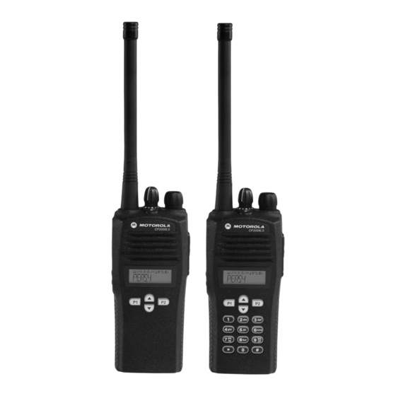
- Page 3 CP200XLS Portable Radio Basic Service Manual VHF 136-162 MHz VHF 146-174 MHz UHF 403-440 MHz UHF 438-470 MHz UHF 465-495 MHz Motorola, Inc. 1301 E. Algonquin Road 68009328001-A Schaumburg, IL 60196...
- Page 4 Motorola. Furthermore, the purchase of Motorola products shall not be deemed to grant either directly or by implication, estoppel, or otherwise, any license under the copyrights, patents or patent applications of Motorola, except for the normal non-exclusive license to use that arises by operation of law in the sale of a product.
- Page 5 Document History The following major changes have been implemented in this manual since the previous edition. Edition Description Date 68009328001-A Initial Release Dec. 2009...
- Page 6 Notes...
-
Page 7: Table Of Contents
Table of Contents Table of Contents List of Figures .....................viii List of Tables ....................x Related Publications ..................x Chapter 1 Model Charts and Test Specifications ......1-1 Radio Model Information........................ 1-1 Model Chart for VHF1 136–162 MHz .................... 1-2 Model Chart for VHF2 146–174 MHz .................... 1-3 VHF Specifications ........................ - Page 8 Table of Contents Radio Tuning Setup ........................5-2 5.3.1 Initial Test Equipment Control Settings................5-3 Transmitter Alignment Options ...................... 5-3 5.4.1 Reference Oscillator Warp ....................5-3 5.4.2 Modulation Balance Attenuation ..................5-4 5.4.3 Transmit Power Tuning ..................... 5-5 5.4.3.1 To Perform Transmit High Power Tuning, do the following: ......5-7 5.4.3.2 To Perform Transmit Low Power Tuning, do the following: - ......
- Page 9 Table of Contents 6.4.2.1 Dust Cover Re-assembly................... 6-9 6.4.2.2 Speaker Re-assembly ..................6-9 6.4.2.3 Keypad and Display/Keyboard Module Re-assembly........6-10 6.4.2.4 Microphone Re-assembly (assemble only after the Display/Keyboard Module is assembled)6-11 6.4.2.5 Chassis Assembly/Re-assembly ..............6-12 6.4.2.6 Chassis and Front Cover Re-assembly ............6-12 6.4.2.7 PTT Re-assembly ....................
- Page 10 Warranty ............................B-1 B.2.1 Warranty Period and Return Instructions................B-1 B.2.2 After Warranty Period .......................B-1 Replacement Parts Ordering ......................B-1 B.3.1 Basic Ordering Information ....................B-1 B.3.2 Motorola Online.........................B-2 B.3.3 Mail Orders ........................B-2 B.3.4 Telephone Orders ......................B-2 B.3.5 Fax Orders ........................B-2 B.3.6 Parts Identification ......................B-2 B.3.7...
-
Page 11: List Of Figures
Table of Contents viii List of Figures Figure 2-1. Major Assemblies Block Diagram..................2-1 Figure 2-2. Transceiver Block Diagram ....................2-2 Figure 3-1. Programming/Test Cable ....................3-4 Figure 3-2. Wiring of the Connectors....................3-4 Figure 4-1. Radio Performance Checks Setup ................... 4-1 Figure 4-2. - Page 12 Table of Contents Figure 7-5. Microphone and Speaker Connections ................7-5 Figure 7-6. Dust Cover Disassembly ....................7-6 Figure 7-7. Removal Speaker-Microphone Assembly ................ 7-6 Figure 7-8. Keypad Removal ......................7-7 Figure 7-10. Removal of Main Board from Chassis ................7-8 Figure 7-9.
-
Page 13: List Of Tables
Table of Contents List of Tables Table 1-1. Radio Model Number (Example: AAH50JDH9AA6AN)............ 1-1 Table 1-2. MIL STDS 810 C, D, E, and F: Applicable to UHF and VHF Specifications (8.2 and 8.4) 1-9 Table 3-1. Recommended Test Equipment..................3-1 Table 3-2. - Page 14 Table of Contents Notes December, 2009 68009328001-A...
-
Page 15: Chapter 1 Model Charts And Test Specifications
Chapter 1 Model Charts and Test Specifications Radio Model Information The model number and serial number are located on a label attached to the back of your radio. You can determine the RF output power, frequency band, protocols, and physical packages. The example below shows one portable radio model number and its specific characteristics. -
Page 16: Model Chart For Vhf1 136-162 Mhz
Model Charts and Test Specifications: Model Chart for VHF1 136–162 MHz Model Chart for VHF1 136–162 MHz CP200XLS, VHF1, 136–162 MHz Model Description AAH50JDF9AA5AN CP200XLS, 136-162 MHz, 5W, 128 Ch. Limited Keypad Model AAH50JDH9AA6AN CP200XLS, 136-162 MHz, 5W, 128 Ch. Full Keypad Model Item Description PMUD2496_... -
Page 17: Model Chart For Vhf2 146-174 Mhz
Model Charts and Test Specifications: Model Chart for VHF2 146–174 MHz Model Chart for VHF2 146–174 MHz CP200XLS, VHF2, 146–174 MHz Model Description AAH50KDF9AA5AN CP200XLS, 146-174 MHz, 5W, 128 Ch. Limited Keypad Model AAH50KDH9AA6AN CP200XLS, 146-174 MHz, 5W, 128 Ch. Full Keypad Model Item Description PMUD2497_... -
Page 18: Vhf Specifications
VHF Specifications VHF Specifications General Transmitter RF Output High Frequency: 136–162 MHz NiMH @ 7.5 V: 146–174 MHz Frequency: 136–162 MHz Channel Capacity: 128 Channels 146–174 MHz 7.5 Volts ±20% Power Supply: Channel Spacing: 12.5/20/25 kHz Dimensions with: Freq. Stability: 0.00025% High Capacity NiCd, 130.5mm H x 62mm W x... -
Page 19: Model Chart For Uhf1 403-440 Mhz
Model Charts and Test Specifications: Model Chart for UHF1 403–440 MHz Model Chart for UHF1 403–440 MHz CP200XLS, UHF1, 403–440 MHz Model Description AAH50QDF9AA5AN CP200XLS, 403-440 MHz, 4W, 128 Ch. Limited Keypad Model AAH50QDH9AA6AN CP200XLS, 403-440 MHz, 4W, 128 Ch. Full Keypad Model Item Description PMUE3577_... -
Page 20: Model Chart For Uhf2 438-470 Mhz
Model Charts and Test Specifications: Model Chart for UHF2 438–470 MHz Model Chart for UHF2 438–470 MHz CP200XLS, UHF2, 438–470 MHz Model Description AAH50RDF9AA5AN CP200XLS, 438-470 MHz, 4 W, 128Ch. Limited Keypad Model AAH50RDH9AA6AN CP200XLS, 438-470 MHz, 4 W, 128Ch. Full Keypad Model Item Description PMUE3578_... -
Page 21: Model Chart For Uhf3 465-495 Mhz
Model Charts and Test Specifications: Model Chart for UHF3 465–495 MHz Model Chart for UHF3 465–495 MHz CP200XLS, UHF3, 465–495 MHz Model Description AAH50SDF9AA5AN CP200XLS 465-495 MHz, 4 W, 128Ch. Limited Keypad Model AAH50SDH9AA6AN CP200XLS 465-495 MHz, 4 W, 128Ch. Full Keypad Model Item Description PMUE3579_... -
Page 22: Uhf Specifications
UHF Specifications UHF Specifications General Transmitter RF Output High Frequency: 403–440 MHz NiMH @ 7.5 V: 438–470 MHz 465–496 MHz Frequency: 403–440 MHz 438–470 MHz Channel Capacity: 128 Channels 465–496 MHz 7.5 Volts ±20% Power Supply: Channel Spacing: 12.5/20/25 kHz Dimensions with: Freq. -
Page 23: Mil Standards
Model Charts and Test Specifications: MIL Standards MIL Standards Table 1-2. MIL STDS 810 C, D, E, and F: Applicable to UHF and VHF Specifications (8.2 and 8.4) Military Standards 810 C, D, E, & F: Parameters/Methods/Procedures 810C 810D 810E 810F Applicable Methods... - Page 24 1-10 Model Charts and Test Specifications: MIL Standards Notes October, 2009 68009328001-A...
-
Page 25: Chapter 2 Theory Of Operation
Chapter 2 Theory Of Operation Introduction This chapter provides a basic theory of operation for the radio components. Major Assemblies • Transceiver Board – contains all transmit, receive, and audio circuitry. • Display (Limited and Full Keypad models only) – 8 characters (14 segments star burst) and 10 icons with backlighting, liquid-crystal display (LCD). -
Page 26: Transmitter
Theory Of Operation: Major Assemblies The IFIC is a low-voltage monolithic FM IF system incorporating a mixer/oscillator, two limiting IF amplifiers, quadrature detector, logarithmic received signal strength indicator (RSSI), voltage regulator and audio, and RSSI Op Amps. The second LO frequency, 44.395 MHz, is determined by a crystal oscillator. -
Page 27: Chapter 3 Test Equipment, Service Aids, And Service Tools
Chapter 3 Test Equipment, Service Aids, and Service Tools Test Equipment Table 3-1 lists test equipment required to service the CP200XLS Radios. Table 3-1. Recommended Test Equipment Motorola Part No. Description Characteristics Application R2600 series System analyzer This item will substitute for... -
Page 28: Service Aids
CP200XLS Radios. While all of these items are available from Motorola, most are standard shop equipment items, and any equivalent item capable of the same performance may be substituted for the item listed. - Page 29 Test Equipment, Service Aids, and Service Tools: Service Aids Table 3-3. Recommended Service Tools (Continued) Motorola Part Description Application 0180386A78 Illuminated magnifying glass with lens attachment Illumination and magnification of components 0180302E51 Master lens system 0180386A82 Anti-static grounding kit Used during all radio assembly and disassembly...
-
Page 30: Figure 3-1. Programming/Test Cable
Test Equipment, Service Aids, and Service Tools: Service Aids Programming/Test Cable 25 POSITION 25 POSITION MALE CONNECTOR FEMALE CONNECTOR 36.0” CABLE 36.0” CABLE Figure 3-1. Programming/Test Cable 25 pin Male D Connector Components molded inside 2.5mm stereo and 3.5mm Orange 3.5mm Tip (Speaker +) Blue... -
Page 31: Chapter 4 Performance Checks
Chapter 4 Performance Checks General The radios meet published specifications through their manufacturing process by utilizing high- accuracy laboratory-quality test equipment. The recommended field service equipment is as accurate as the manufacturing equipment with few exceptions. This accuracy must be maintained in compliance with the manufacturer’s recommended calibration schedule. -
Page 32: Rf Test Mode
Performance Checks: RF Test Mode Initial equipment control settings should be as indicated in Table 4-1 and should be the same for all performance checks and tuner alignment procedures. Table 4-1. Initial Equipment Control Settings Service Monitor Test Set Power Supply Monitor Mode: Power Monitor Spkr set: A Voltage: 7.5 Vdc... -
Page 33: Table 4-2. Test Environments
Performance Checks: RF Test Mode To enter test mode: 1. Turn the radio on. Within ten seconds after the self test is complete (self test tone is heard), press SB2 (Side Button 2 in Figure 4-2) five times in succession. If the self test complete tone is not heard, see Error Codes information in Chapter 9. -
Page 34: Table 4-5. Receiver Performance Checks
Performance Checks: RF Test Mode Table 4-4. Test Frequencies VHF 1 VHF 2 UHF 1 UHF 2 UHF 3 Channel Selector Test Channel (136-162 (146-174 (403-440 (438-470 (465-495 Switch Position MHz) MHz) MHz) MHz) MHz) 1 Low Power TX#1 or #8 136.625 146.625 403.625... -
Page 35: Table 4-6. Transmitter Performance Checks
Performance Checks: RF Test Mode * See Table 4-4 Table 4-6. Transmitter Performance Checks Test Name Communications Analyzer Radio Test Set Comments Reference Mode: PWR MON TEST MODE, PTT to continu- Frequency error to be Frequency Test Channel 4 ous (during the ±186 Hz VHF1 4th channel test frequency carrier squelch... - Page 36 Performance Checks: RF Test Mode Notes October, 2009 68009328001-A...
-
Page 37: Chapter 5 Radio Alignment Procedures
Chapter 5 Radio Alignment Procedures Introduction This chapter provides an overview of the Commercial Series Customer Programming Software (CPS) and the Global Tuner as designed for use in a Windows® 98/NT4/2000/ME/XP environment. Both cover all the functions of the traditional Radio Service Software (RSS) package. -
Page 38: Radio Tuning Setup
Radio Alignment Procedures: Radio Tuning Setup Radio Tuning Setup A Windows 98/NT4/2000/ME/XP PC (personal computer) and Global Tuner are required to tune the radio. To perform the tuning procedures, the radio must be connected to the PC, RIB (Radio Interface Box) and Universal Test Set as shown in Figure 5-2 below. -
Page 39: Initial Test Equipment Control Settings
Radio Alignment Procedures: Transmitter Alignment Options 5.3.1 Initial Test Equipment Control Settings The initial test equipment control settings are listed in Table 5-1. Table 5-1. Initial Equipment Control Settings Service Monitor Test Set Power Supply Monitor Mode: Power Monitor Speaker set: A Voltage: 13.2 Vdc RF Attenuation: -70 Speaker/load:... -
Page 40: Modulation Balance Attenuation
Radio Alignment Procedures: Transmitter Alignment Options 1. Under Tx Align menu, select Reference Oscillator Warp (Figure 5-3). 2. There is only 1 frequency point shown which is always the last non-0 transmit frequency point, which will normally be F7. 3. Click on the slider thumb and press PTT Toggle to key up the radio at the corresponding frequency point. -
Page 41: Transmit Power Tuning
Radio Alignment Procedures: Transmitter Alignment Options Figure 5-4. Modulation Balance Window Compensation alignment balances the modulation sensitivity of the VCO and reference modulation (synthesizer low frequency port) lines. The compensation algorithm is critical to the operation of signaling schemes that have very low frequency components (Digital Private-Line) and could result in distorted waveforms if improperly adjusted. -
Page 42: Figure 5-5. Transmit Power Window (High Power)
Radio Alignment Procedures: Transmitter Alignment Options Note: When checking the RF power output of the radio with a test set, always use a pad of at least 30 dB attached to the radio end of the RF cable. This will avoid an RF mismatch and ensure a stable RF reading that will not change with varying lengths of connecting cable Figure 5-5. -
Page 43: To Perform Transmit High Power Tuning, Do The Following
Radio Alignment Procedures: Transmitter Alignment Options Table 5-3. Transmit High/Low Power Level RF Band (MHz) Model Number High Power(W) Low Power (W) VHF 136-162 MHz AAH50JDF9AA5AN 5.2-5.5 1.1-1.3 VHF 136-162 MHz AAH50JDH9AA6AN 5.2-5.5 1.1-1.3 VHF 146-174 MHz AAH50KDF9AA5AN 5.2-5.5 1.1-1.3 VHF 146-174 MHz AAH50KDH9AA6AN 5.2-5.5... -
Page 44: Vco Attenuation
Radio Alignment Procedures: Transmitter Alignment Options 8. Exit the Transmit Low Power function. 5.4.4 VCO Attenuation Note: Modulation Balance Tuning must be done first. The Transmit Deviation Limit softpot sets the maximum deviation of the carrier. Tuning is performed for all (12.5 kHz, 20 kHz and 25 kHz) channel bandwidths. -
Page 45: Vco Attenuation 25 Khz
Radio Alignment Procedures: Transmitter Alignment Options 5.4.4.1 VCO Attenuation 25 kHz 1. Under the Tx Align menu, select VCO Attenuation 25 kHz (Figure 5-6). 2. Begin with the lowest frequency. Select the thumb of the slider at the lowest frequency point and then press the PTT Toggle button to key up the radio at the corresponding frequency point. -
Page 46: Dtmf Deviation Tuning
5-10 Radio Alignment Procedures: Transmitter Alignment Options Table 5-4. Deviation Specifications Band Channel Spacing Deviation (kHz) UHF/VHF 25 kHz 4.40 - 4.60 UHF/VHF 12.5 kHz 2.20 - 2.30 UHF/VHF 20 kHz 3.40 - 3.60 5.4.5 DTMF Deviation Tuning This tuning option controls the Dual Tone MultiFrequency deviation. Please note that Modulation Balancing and VCO Attenuation have to be performed prior to this tuning operation. -
Page 47: Mdc1200 Deviation Tuning (Mdc Radios Only)
Radio Alignment Procedures: Receiver Tuning 5-11 5.4.6 MDC1200 Deviation Tuning (MDC radios only) This tuning option controls the MDC1200 Signaling deviation. Please note that Modulation Balancing and VCO Attenuation have to be performed prior to this tuning operation. Not doing so will result in the wrong deviation value being obtained while tuning this feature. -
Page 48: Rated Volume Tuning
5-12 Radio Alignment Procedures: Receiver Tuning 5.5.1 Rated Volume Tuning Note: When using test box RLN4460, the received audio output is taken from the AC/DC METER OUT terminals with the METER OUT rotary switch set to RX. The rated audio tuning procedure automatically configures the radio for 25 KHz. -
Page 49: Squelch Tuning
Radio Alignment Procedures: Receiver Tuning 5-13 5.5.2 Squelch Tuning Note: 1. Squelch tuning can only be accomplished after reference oscillator warping. 2. When using the test box RLN4460, the received audio output is taken from the AC/ DC METER OUT terminals with the METER OUT rotary switch set to RX. It is recommended that Rated Volume Tuning be performed so the the correct 10 dB SINAD level can be obtained. -
Page 50: Auto Tune
5-14 Radio Alignment Procedures: Receiver Tuning 3. Set softpot to its maximum value to mute the radio. 4. Adjust the softpot value by using the slider, keying in the edit box or using the spin controls. Press ENTER to confirm the selection or use the spin controls. Do this until the radio is totally unmuted. Verify the squelch closing by inputting a signal level of 4 dB lower than that of the 10 dB SINAD level. -
Page 51: Rssi Display Tuning
Radio Alignment Procedures: Utilities 5-15 5. Adjust the input level to reflect the next softspot value. Repeat steps 3 and 4 to tune the next value. 5.5.4 RSSI Display Tuning 1. Under the Rx Align menu, select RSSI Display Tuning. 2. -
Page 52: Figure 5-12. Side Button Locations
5-16 Radio Alignment Procedures: Radio-to-Radio Cloning Procedure: 1. Turn source and target radios off. 2. Connect cloning cable (AAPMKN4003) to the side connector of both radios. 3. Turn on the destination radio. 4. Press and hold the two side buttons at the same time on the source radio and then power up the source radio (Figure 5-12). -
Page 53: Chapter 6 Full Keypad Model Disassembly And Re-Assembly
Chapter 6 Full Keypad Model Disassembly and Re-assembly Introduction This section provides details about the following: • Preventive maintenance (inspection and cleaning) • Safe handling of CMOS and LDMOS devices • Disassembly and re-assembly of the radio • Repair procedures and techniques Preventive Maintenance The radios do not require a scheduled preventive maintenance program;... -
Page 54: Safe Handling Of Cmos And Ldmos Devices
• Wear a conductive wrist strap in series with a 100k resistor to ground. (Replacement wrist straps that connect to the bench top covering are Motorola part number RSX-4015.) • Do not wear nylon clothing while handling CMOS devices. -
Page 55: Disassembling And Re-Assembling The Radio - General
TORX™ T6 screwdriver If a unit requires more complete testing or service than is customarily performed at the basic level, send this unit to a Motorola Authorized Service Center. See Appendix B for a list of authorized service centers. The following disassembly procedures should be performed only if necessary: •... -
Page 56: Figure 6-2. Antenna And Knob Removal
Full Keypad Model Disassembly and Re-assembly: Disassembling and Re-assembling the Radio — General 3. Remove the antenna. 4. Pry off the volume and channel selector knobs from their shafts using the knob removal/chassis opener tool (Motorola part # 6686533Z01). (Figure 6-2). -
Page 57: Figure 6-4. Keyboard Flex Connection
Full Keypad Model Disassembly and Re-assembly: Disassembling and Re-assembling the Radio — General CAUTION: Marring the front cover O-ring sealing area will prevent the radio from sealing properly. If the O-ring is damaged, replace it with a new one. W A R N I N G 6. -
Page 58: Dust Cover Disassembly
Full Keypad Model Disassembly and Re-assembly: Disassembling and Re-assembling the Radio — General 6.4.1.2 Dust Cover Disassembly 1. Gently pry the top of the dust cover away from the body of the radio. (See Figure 6-6). 2. Rotate the dust cover 90° in a counterclockwise direction to allow the key to be removed. 3. -
Page 59: Keyboard Removal
Full Keypad Model Disassembly and Re-assembly: Disassembling and Re-assembling the Radio — General 6.4.1.4 Keyboard Removal 1. Unscrew the four screws that secure the retaining shield using a T5 Torx screwdriver. 2. Lift the Display/Keypad Module out of the housing, being careful not to damage flex cable (Figure 6-8). -
Page 60: Chassis Disassembly
Full Keypad Model Disassembly and Re-assembly: Disassembling and Re-assembling the Radio — General Flat Blade Hooks Screwdriver PTT Seal Figure 6-9. PTT Removal 6.4.1.6 Chassis Disassembly 1. Remove the O-ring. 2. Use a Torx™ screwdriver with a T6 bit to remove the four screws (Figure 6-10) holding the main board to the chassis. -
Page 61: Radio Re-Assembly - Detailed
Full Keypad Model Disassembly and Re-assembly: Disassembling and Re-assembling the Radio — General 6.4.2 Radio Re-assembly - Detailed 6.4.2.1 Dust Cover Re-assembly 1. Insert the tail of the dust cap into the bottom hole of the audio jacks housing opening (Figure 6-11). -
Page 62: Keypad And Display/Keyboard Module Re-Assembly
6-10 Full Keypad Model Disassembly and Re-assembly: Disassembling and Re-assembling the Radio — General 4. Ensure the speaker is seated flush in the housing. 5. Insert the speaker retainer tab into the slot in the front housing (see Figure 6-12). Note: When fastening the speaker retainer screw, make sure the wires are out of the way to prevent pinching by the retainer. -
Page 63: Microphone Re-Assembly (Assemble Only After The Display/Keyboard Module Is Assembled)6-11
Full Keypad Model Disassembly and Re-assembly: Disassembling and Re-assembling the Radio — General 6-11 Figure 6-14. Display/Keypad Module Re-assembly (2) 6.4.2.4 Microphone Re-assembly (assemble only after the Display/Keyboard Module is assembled) 1. Check that the microphone felt is in position and not damaged. If damaged, replace felt. 2. -
Page 64: Chassis Assembly/Re-Assembly
6-12 Full Keypad Model Disassembly and Re-assembly: Disassembling and Re-assembling the Radio — General 6.4.2.5 Chassis Assembly/Re-assembly 1. Replace the battery contact seal (if necessary) surrounding the battery contact (Figure 6-16). 2. Remove the old Interface Pad from the chassis by scraping off the pad and adhesive with a straight razor. -
Page 65: Figure 6-17. Microphone And Speaker Re-Assembly
Full Keypad Model Disassembly and Re-assembly: Disassembling and Re-assembling the Radio — General 6-13 Note: Ensure that the plug orientation is correct with the exposed pins in the wire casing facing upward and fully plugged in. Connect the speaker wire assembly into the 2-pin connector on the main board and bend the wires at the board connector so the wires are positioned toward the top of the radio (Figure... -
Page 66: Ptt Re-Assembly
6-14 Full Keypad Model Disassembly and Re-assembly: Disassembling and Re-assembling the Radio — General the board into the housing, perform the following checks: Open the dust cap and ensure the wires are not pinched between the shroud and housing. Ensure the O-ring is seated in the groove. Ensure that the bottom side of the dust cap is fully pressed into the housing before the snapping the board into place. -
Page 67: Mechanical View And Parts List
Full Keypad Model Disassembly and Re-assembly: Mechanical View and Parts List 6-15 Mechanical View and Parts List 6.5.1 CP200XLS Full-Keypad Exploded View and Parts List Figure 6-21. CP200XLS Full Keypad Radio Exploded View 68009328001-A December, 2009... - Page 68 Motorola Motorola Item Part Description Item Part Description Number Number See Appendix Antenna NON-REFERENCED ITEMS 54012047001 Nameplate, Motorola 3680530Z02 Knob, Frequency 1386440Z03 Escutcheon, Top 03012009001 Screw M1.6X.64 Self-tapping 15012016001 Housing, Full, with Lens 35012012001 Speaker, Felt 3886489Z02 PTT, Rubber 4586439Z01...
-
Page 69: Chapter 7 Limited Keypad Model Disassembly And Re-Assembly
Chapter 7 Limited Keypad Model Disassembly and Re-assembly Introduction This section provides details about the following: • Preventive maintenance (inspection and cleaning) • Safe handling of CMOS and LDMOS devices • Disassembly and re-assembly of the radio • Repair procedures and techniques Preventive Maintenance The radios do not require a scheduled preventive maintenance program;... -
Page 70: Safe Handling Of Cmos And Ldmos Devices
• Wear a conductive wrist strap in series with a 100k resistor to ground. (Replacement wrist straps that connect to the bench top covering are Motorola part number RSX- 4015.) • Do not wear nylon clothing while handling CMOS devices. -
Page 71: Disassembling And Re-Assembling The Radio - General
TORX™ T6 screwdriver If a unit requires more complete testing or service than is customarily performed at the basic level, send this unit to a Motorola Authorized Service Center. See Appendix B for a list of authorized service centers. The following disassembly procedures should be performed only if necessary: •... -
Page 72: Figure 7-2. Antenna And Knob Removal
7-4 Limited Keypad Model Disassembly and Re-assembly: Disassembling and Re-assembling the Radio — General 4. Pry off the volume and channel selector knobs from their shafts using the knob remover/chassis opener tool (Motorola part # 6686533Z01) (Figure 7-2). Figure 7-2. Antenna and Knob Removal Note: Both knobs slide on and off. -
Page 73: Figure 7-4. Keyboard Flex Connection
Limited Keypad Model Disassembly and Re-assembly: Disassembling and Re-assembling the Radio — General 7-5 Note: The speaker wire assembly microphone wire assembly and keypad flex cable connecting the front housing assembly and the chassis prevent the two units from being completely separated. -
Page 74: Dust Cover Disassembly
7-6 Limited Keypad Model Disassembly and Re-assembly: Disassembling and Re-assembling the Radio — General 7.4.1.2 Dust Cover Disassembly 1. Gently pry the top of the dust cover away from the body of the radio. (See Figure 7-6). 2. Rotate the dust cover 90° in a counterclockwise direction to allow the key to be removed. 3. -
Page 75: Keyboard Removal
Limited Keypad Model Disassembly and Re-assembly: Disassembling and Re-assembling the Radio — General 7-7 7.4.1.4 Keyboard Removal 1. Unscrew the four screws that secure the retaining shield using a T5 Torx screwdriver. 2. Lift the Display/Keypad Module out of the housing, being careful not to damage flex cable (Figure 7-8). -
Page 76: Chassis Disassembly
7-8 Limited Keypad Model Disassembly and Re-assembly: Disassembling and Re-assembling the Radio — General Flat Blade Hooks Screwdriver PTT Seal Figure 7-9. PTT Removal 7.4.2 Chassis Disassembly CAUTION: Refer to the CMOS CAUTION paragraph (see 3.3) before removing the main board. Be sure to use Electrostatic Discharge protection when handling circuit boards. -
Page 77: Radio Re-Assembly - Detailed
Limited Keypad Model Disassembly and Re-assembly: Disassembling and Re-assembling the Radio — General 7-9 7.4.3 Radio Re-assembly - Detailed 7.4.3.1 Dust Cover Re-assembly 1. Insert the tail of the dust cap into the bottom hole of the audio jacks housing opening (Figure 7-11). -
Page 78: Keypad And Display/Keyboard Module Re-Assembly
7-10 Limited Keypad Model Disassembly and Re-assembly: Disassembling and Re-assembling the Radio — General 4. Ensure the speaker is seated flush in the housing. 5. Insert the speaker retainer tab into the slot in the front housing (see Figure 7-12). Note: When fastening the speaker retainer screw, make sure the wires are out of the way to prevent pinching by the retainer. -
Page 79: Microphone Re-Assembly (Assemble Only After The Display/Keyboard Module Is Assembled)7-11
Limited Keypad Model Disassembly and Re-assembly: Disassembling and Re-assembling the Radio — General 7-11 Figure 7-14. Display/Keypad Module Re-assembly (2) 7.4.3.4 Microphone Re-assembly (assemble only after the Display/Keyboard Module is assembled) 1. Check that the microphone felt is in position and not damaged. If damaged, replace felt. 2. -
Page 80: Chassis Assembly/Re-Assembly
7-12 Limited Keypad Model Disassembly and Re-assembly: Disassembling and Re-assembling the Radio — General 7.4.3.5 Chassis Assembly/Re-assembly 1. Replace the battery contact seal (if necessary) surrounding the battery contact (Figure 7-16). 2. Remove the old Interface Pad from the chassis by scraping off the pad and adhesive with a straight razor. - Page 81 Limited Keypad Model Disassembly and Re-assembly: Disassembling and Re-assembling the Radio — General 7-13 Note: Ensure that the plug orientation is correct with the exposed pins in the wire casing facing upward and fully plugged in. Connect the speaker wire assembly into the 2-pin connector on the main board and bend the wires at the board connector so the wires are positioned toward the top of the radio (Figure...
-
Page 82: Ptt Re-Assembly
7-14 Limited Keypad Model Disassembly and Re-assembly: Disassembling and Re-assembling the Radio — General 4. Push the topside of the board chassis upward until it touches the housing end. Before snapping the board into the housing, perform the following checks: Open the dust cap and ensure the wires are not pinched between the shroud and housing. -
Page 83: Mechanical View And Parts List
Limited Keypad Model Disassembly and Re-assembly: Mechanical View and Parts List 7-15 Mechanical View and Parts List 7.5.1 CP200XLS Limited-Keypad Exploded View and Parts List Figure 7-21. CP200XLS Limited Keypad Radio Exploded View 68009328001-A December, 2009... - Page 84 Motorola Motorola Item Part Description Item Part Description Number Number See Appendix Antenna NON-REFERENCED ITEMS 54012047001 Nameplate, Motorola 3680530Z02 Knob, Frequency 1386440Z03 Escutcheon, Top 03012009001 Screw M1.6X.64 Self-tapping 15012016002 Housing, Limited, with Lens 35012012001 Speaker, Felt 3886489Z02 PTT, Rubber 4586439Z01...
-
Page 85: Chapter 9 Troubleshooting Tables
Chapter 9 Troubleshooting Tables Power-Up Error Codes During radio power-up, the radio performs dynamic tests to determine if the radio is working properly. Problems detected during these tests are presented as an error code on the radio’s display. The presence of an error code should prompt a user that a problem exists and that a service technician should be contacted. -
Page 86: Troubleshooting Table For Receiver
Troubleshooting Tables: Troubleshooting Table for Receiver Troubleshooting Table for Receiver Table Table 9-3 lists the possible causes of, and corrections for, receiver problems. Table 9-3. Receiver Troubleshooting Table Corrective or Test Symptom Possible Causes (Measurements at Room Temperature) Radio Dead; Display Does 1. -
Page 87: Troubleshooting Table For Transmitter
Troubleshooting Tables: Troubleshooting Table for Transmitter Troubleshooting Table for Transmitter Table Table 9-4 lists the possible causes of, and corrections for, transmitter problems. Table 9-4. Transmitter Troubleshooting Table Corrective or Test Symptom Possible Causes (Measurements at Room Temperature) No RF Power Out 1. - Page 88 Troubleshooting Tables: Troubleshooting Table for Transmitter Notes December, 2009 68009328001-A...
-
Page 89: Appendix A Accessories
Appendix A Accessories Antennas NAD6502_R VHF Heliflex Antenna 14cm (146-174 MHz) HAD9742 VHF Stubby Antenna, 9cm (146-162 MHz) HAD9743 VHF Stubby Antenna, 9cm (162-174 MHz) NAE6522_R UHF Heliflex Stubby Antenna 9cm (438-470 MHz) NAE6483_R Flexible Whip Antenna (403-520 MHz) 8505816K26 UHF Heliflex Stubby (470-520 MHz) Carrying Accessories RLN5496... - Page 90 Accessories: Batteries NNTN4496_R NiCd, 1100 mAH NNTN4497_R Li-lon, 1800 mAH NNTN4851 NiMH, 1400 mAH NNTN4970 Slim Li-Ion, 1600 mAH Audio Accessories HMN9752 Earpiece with Volume Control, 1-Wire (plastic earloop) (Beige) HMN9727 Earpiece without Volume Control, 1-Wire (plastic earloop) (Beige) RLN4894 Earpiece without Volume Control, 1-Wire (plastic earloop) (Black) HMN9754 Earpiece with Microphone &...
- Page 91 Accessories: BDN6648 Heavy Duty Dual Muff Headset with Noise Canceling Microphone RMN5015 Heavy Duty Dual Muff Racing Headset (requires RKN4090 Headset Adapter Cable) RKN4090 Adapter Cable for use with RMN5015 Racing Headset RMN4051 2-Way Hard Hat Mount, Black, Noise Reduction Rating (22db) (requires RKN4094 Adapter Cable) RMN4054 Receive-Only Hard Hat Mount Headset with 3.5mm Right Angle Plug...
- Page 92 Accessories: Notes October, 2009 68009328001-A...
-
Page 93: Appendix B Warranty, Service Support, And Replacement Parts
In instances where the product is covered under a “return for replacement” or “return for repair” warranty, a check of the product should be performed prior to shipping the unit back to Motorola. This is to ensure that the product has been correctly programmed or has not been subjected to damage outside the terms of the warranty. -
Page 94: Motorola Online
Warranty, Service Support, and Replacement Parts: Replacement Parts Ordering B.3.2 Motorola Online Motorola online users can access our on-line catalog at: http://www.motorola.com/governmentandenterprise. To register for online access, please call 800-814-0601 (for U.S. and Canada Service Centers only). B.3.3 Mail Orders... -
Page 95: Product Customer Service
Technical support is available to assist the dealer/distributor in resolving any malfunction which may be encountered. Initial contact should be by telephone wherever possible. When contacting Motorola Technical Support (Customer Resources), be prepared to provide the product model number and the unit’s serial number. - Page 96 Warranty, Service Support, and Replacement Parts: Technical Support Notes December, 2009 68009328001-A...
-
Page 97: Glossary
Micro Controller Unit MRTI Motorola Radio-Telephone Interconnect: a system that provides a repeater connection to the Public Switched Telephone Network (PSTN). The MRTI allows the radio to access the telephone network when the proper access code is received. - Page 98 Term Definition Phase-Locked Loop: a circuit in which an oscillator is kept in phase with a reference, usually after passing through a frequency divider. Push-To-Talk: the switch located on the left side of the radio; when pressed, causes the radio to transmit. Random Access Memory: the radio’s RAM is loaded with a copy of the EEPROM data.