Zanussi GAS HOB ZGF 982 Instruction Booklet
Zanussi cooktop user manual
Hide thumbs
Also See for GAS HOB ZGF 982:
- Instruction booklet (16 pages) ,
- Instruction booklet (32 pages)

Related Manuals for Zanussi GAS HOB ZGF 982


Summary of Contents for Zanussi GAS HOB ZGF 982
-
Page 1: Gas Hob
GAS HOB MODEL ZGF 982 INSTRUCTION BOOKLET Please read this instruction booklet before using the appliance... -
Page 2: Important Safety Information
Important Safety Information You MUST read hese warnings carefully before installing or using the hob. If you need assistance, contact our Customer Care Department on 08705 727727 Installation This hob must be installed by qualified personnel, according to the manufacturer’s instructions and to the relevant British Standards. -
Page 3: Table Of Contents
For the User Description of the Hob Operation Maintenance and Cleaning Something Not Working Service and Spare Parts Peace of Mind for 24 Months Guide to Use the instructions The following symbols will be found in the text to guide you throughout the Instructions: Safety Instructions Step by step instructions for an operation... -
Page 4: Description Of The Hob
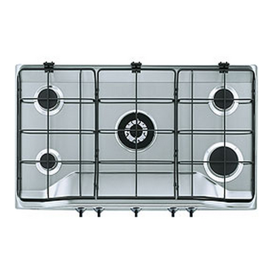
Description of the Hob Hob Top Auxiliary Burner Semi-rapid Burners Ultra-rapid Double-crown Burner Rapid Burner Ignition pushbutton Control knob for front left burner (auxiliary) Control knob for back left burner (semi-rapid) Control knob for central burner (ultra-rapid) 10. Control knob for back right burner (semi-rapid) 11. -
Page 5: Operation
Take care when frying food in hot oil or fat, as the overheated splashes could easily ignite. If the control knobs become difficult to turn, please contact your local Zanussi Service Force Centre. maximum diameter 260 mm. -
Page 6: Maintenance And Cleaning
Maintenance and Cleaning Before any maintenance or cleaning can be carried out, you must DISCONNECT the hob from the electricity supply. The hob is best cleaned whilst it is still warm, as spillage can be removed more easily than if it is left to cool. -
Page 7: Something Not Working
Something Not Working? If the hob is not working correctly, please carry out the following checks before contacting your local Zanussi Service Force Centre. IMPORTANT: If you call out an engineer to a fault listed below, or to repair a fault caused by incorrect use or installation, a charge will be made even if the appliance is under guarantee. -
Page 8: Peace Of Mind For 24 Months
Peace of Mind for 24 Months ZANUSSI GUARANTEE CONDITIONS We, Zanussi, undertake that if, within 24 months of the date of the purchase, this Zanussi appliance or any part thereof is proved to be defective by any reason only of faulty workmanship or materials, we... -
Page 9: Technical Data
Instructions for the Installer Engineer technical data OVERALL DIMENSIONS Width: 860 mm. Depth: 510 mm. Height: 72 mm. Weight: 12 Kg. CUT OUT DIMENSIONS Width: 830 mm. Depth: 480 mm. Thickness: 30 mm. Ignition HT Spark Spark Generator Ispra Control's BF 50066 - 240V 0.6 YA T 120 Spark Gap Fixed Rear Left Burner (semi rapid) -
Page 10: Important Safety Requirements
If there are other fuel burning appliances in the same room, B.S. 5440 Part 2 Current Edition, should be consulted to determine the requisite air vent requirements. INSTALLATION GUIDANCE INSTRUCTIONS CLEARANCES REQUIRED WHEN FITTING ZANUSSI GAS HOB WITHOUT A COOKER HOOD ABOVE 700 mm 400 mm FO 2027* Location... -
Page 11: Installation
Installation IMPORTANT This hob must be installed by qualified personnel to the relevant British Standards. Any gas installation must be carried out by a registered CORGI installer. The manufacturer will not accept liability, should the above instructions or any of the other safety instructions incorporated in this book be ignored. -
Page 12: Building In
Building In Building over a cupboard or drawer If the hob is to be installed above a cupboard or drawer it will be necessary to fit a heat resistant board below the base of the hob on the underside of the work surface. -
Page 13: Electrical Connection
Electrical connections Any electrical work required to install this hob should be carried out by a qualified electrician or competent person, in accordance with the current regulations. THIS HOB MUST BE EARTHED. The manufacturer declines any liability should these safety measures not be observed. -
Page 14: Wiring Diagram
Wiring Diagram 220/240 A. IGNITOR SWITCH B. IGNITOR UNIT... -
Page 15: Fault Finding
Fault Finding Preliminary Electrical Systems Check Blue Brown Green Yellow START Isolate appliance and carry out: A: Earth Continuity check. Blue Green Brown Yellow Has inlet fuse blown? Inlet wiring faulty. Rectify any fault. PLUG (with cover removed) Earth Wire Green/Yellow Neutral Wire Blue... - Page 16 Ignition System / Gas Ignition Ignitor does not spark Check plug top fuse and replace if necessary Check polarity and earth continuity of supply point Check earth continuity of appliance Check continuity from 'N' on the mains connector block and "O" on the ignitor unit Check continuity from 'L' on the mains connector block and the...
-
Page 17: Commissioning
Commissioning When the hob has been fully installed it will be necessary to check the minimum flame setting. To do this, follow the procedure below. - Turn the gas tap to the MAX position and ignite. - Set the gas tap to the MIN flame position then turn the control knob from MIN to MAX several times.