Table of Contents
Advertisement
Quick Links
TM 11-6625-1614-15
D E P A R T M E N T
AND DEPOT MAINTENANCE MANUAL
H E A D Q U A R T E R S , D E P A R T M E N T O F T H E A R M Y
O F
T H E
A R M Y
ORGANIZATIONAL, DS, GS,
HEWLETT-PACKARD
ELECTRONIC VOLTMETER
MODEL 410C
T h i s c o p y
a
r e p r i n t
I S
p a g e s
f r o m
C h a n g e
AUGUST 1967
T E C H N I C A L
w h i c h
i n c l u d e s
c u r r e n t
1 .
M A N U A L
Advertisement
Table of Contents

Related Manuals for HP 410C


Summary of Contents for HP 410C
- Page 1 ORGANIZATIONAL, DS, GS, AND DEPOT MAINTENANCE MANUAL HEWLETT-PACKARD ELECTRONIC VOLTMETER MODEL 410C T h i s c o p y r e p r i n t w h i c h i n c l u d e s...
- Page 2 TM 11-6625-1614-15 WARNING DANGEROUS VOLTAGES EXIST IN THIS EQUIPMENT Be careful when working on the power supplies a n d t h e i r c i r c u i t s , o r o n t h e 1 1 5 - o r 2 3 0 - v o l t a c l i n e c o n n e c t i o n s .
-
Page 3: Table Of Contents
DEPARTMENT OF THE ARMY No. 11-6625-1614-15) , DC, 28 August 1 9 6 7 A S H I N G T O N ORGANIZATIONAL, DS, GS, AND DEPOT MAINTENANCE MANUAL HEWLETT–PACKARD ELECTRONIC VOLTMETER MODEL 410C (NSN 6625-00-969-4105) Page Section GENERAL INFORMATION ------------------------------------------------------------------------------------------- 1-A.1. - Page 4 LIST OF ILLUSTRATIONS Number Page Model 410C Electronic Voltmeter 1-1. 2-1. The Combining Case ....................
- Page 5 TM 11-6625-1614-15 Page Number 4-4. Simplified Schematic, DC Voltage Measurements -------------------------------------------------------------- 4-5. Simplified Schematic, Resistance Measurement ----------------------------------------------------------------- 4-6. Simplified Schematic, AC Voltage Measurement --------------------------------------------------------------- 5-1. Alternate Voltage Source --------------------------------------------------------------------------------------------- DC Ammeter Operation ---------------------------------------------------------------------------------------------- 5-2. 5-3. High Frequency Response Test -------------------------------------------------------------------------------------- 5-4.
-
Page 7: General Information
(DS), general support (GS), and depot mending Improvements maintenance. It describes Hewlett-Packard (Federal supply code 28480) Electronic Voltmeter Model 410C. can help improve this manual. If you find any mistakes or if you know of a way to improve the pro-... - Page 9 11-6625-1614-15 Model 410C Section I Table 1-1 01556-2...
-
Page 10: Description
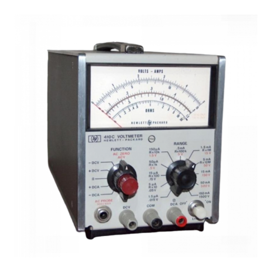
±5% of reading at midscale; resistance from 0.2 ohms to 500 megohms can be measured with reduced accuracy. The Model 410C Electronic Voltmeter is shown in Figure 1-1; the specifications are given in Table 1-1. 1-3. With the Model 11036A detachable AC Probe, the Voltmeter can be used to measure AC voltage from 20 cps to 700 Mc. -
Page 11: Accessories Available
700 Mc, with indications obtainable to 3000 Mc. Frequency response at 100 Mc is within ±2%. The Model 110364 responds to the positive-peak-above-average value of the signal applied. The Model 410C is calibrated to read in RMS volts, for sine wave inputs . 1 - 5... -
Page 12: The Combining Case
Model 410C TM 11-6625-1614-15 Section II Figures 2-l and 2-2 Figure 2-1. The Combining Case 2-2. Steps to Place Instrument in Combining Case Figure 01556-1... -
Page 13: Installation
However, the instrument should not be operated where the ambient temperature exceeds 55° C (140° F). 2-13. The Modei 410C can be operated from either 115 or 230 volts, 50 to 1000 cps. The instrument can be easily converted from i 15- to 230- volt operation. -
Page 14: Repackaging For Shipment
TM 11-6625-1614-15 Section II Model 410C Paragraph 2-14 to 2-15 DO NOT CHANGE THE SETTING OF THE LINE VOLTAGE SWITCH WHEN THE VOLT- METER IS OPERATING. 2-14. REPACKAGING FOR SHIPMENT. 2-15. The following paragraphs contain a general guide for repackaging of the instrument for shipment. -
Page 15: Operation
AC VOLTAGE MEASUREMENT (Figure 3-4). 3-13. 3-1. INTRODUCTION. 3-2. The Model 410C is used to measure AC and DC voltage, DC current, and resistance. All measure- ONE SIDE OF ALMOST ALL POWER ment inputs are located on the front panel; a DC out- DISTRIBUTION SYSTEMS IS GROUNDED. -
Page 16: Front And Rear Panel Controls
TM 11-6625-1614-15 Model 410C Section III Figure 3-1 FUNCTION SELECTOR: This control is used DCV: This lead is used in conjunction with the selecting type of measurement to be made. They COM Lead to measure ±DC voltage. are: ±DC Voltage, ±DC Current, AC Voltage, and resistance measurements. - Page 17 TM 11-6625-1614-15 Section III Model 410C Paragraphs 3-19 to 3-27 and Table 3-1 second maY be made without loss of accuracy by re- 3-23. T connect the probe into an existing coaxial moving the. plastic nose on the Model 11036A and using transmission line, cut the line away so the center con- in its place a 0.25 microfarad blocking capacitor in...
-
Page 18: Negative Pulses
Solving the expression for the multiplying factor, 3-33. MEASURING DC NANO-AMPERE CURRENT (Figure 3-8). 3-34. The Model 410C can be used to measure nano- ampere leakage current in transistors and diodes. The three most sensitive DC voltage measurement ranges are used to measure DC nano-ampere currents. - Page 19 TM 11-6625-1614-15 Section III Model 410C F i g u r e 3 - 2 Figure 3-2. DC Voltage Measurements 01556-2...
-
Page 20: Dc Current Measurements
TM 11-6625-1614-15 Section III Model 410C Figure 3-3 Figure 3-3. DC Current Measurements 01556-3... - Page 21 TM 11-6625-1614-15 Model 410C Section III Model 410C Figure 3-4. AC Voltage Measurements 01556-3...
-
Page 23: Graph Used In Calculation Of Pulse Voltage Readings
TM 11-6625-1614-15 Section III Model 410C Figure 3-6 Figure 3-6. Graph Used in Calculation of Pulse Voltage Readings 01556-2... -
Page 24: Resistance Measurements
TM 11-6625-1614-15 Section III Model 410C Figure 3-7 Figure 3-7. Resistance Measurements 3-10 01556-2... - Page 25 TM 11-6625-1614-15 Model 410C Section III Figure 3-8 DC Nano-Amoere Current Measurements Figure 3-8. 01556-3 3-11...
-
Page 26: Block Diagram, Model 410C
Figure 4-1 and 4-2 Figure 4-1. Block Diagram, Model 410C F i g u r e 4 - 2 . M o d u l a t o r - D e m o d u l a t o r M e c h a n i c a l A n a l o g y... -
Page 27: Theory Of Operation
- amplifier- demodulator, and a meter circuit. A block diagram of the Model 410C is shown 4-10. The resistor R1 (located in the DCV probe) in in Figure 4-1. conjunction with resistors A2R10 through A2R26, pro- vides the 10 megohm input impedance required for the three most sensitive DCV ranges. -
Page 28: The Feedback Network
AC probe diode, A8V1, so that the 4-23. THE FEEDBACK NETWORK. filament remains warm when the Modei 410C is being used in modes of operation other than ACV. W h e n 4-24. The feedback network drives the meter and FUNCTION selector A1S1 is switched to ACV, 6.0... -
Page 34: Recommended Test Equipment
TM 11-6625-1614-15 Model 410C Section V Table 5-1 Table 5-1. Recommended Test Equipment 01556-2... -
Page 35: Vmaintenance
During performance checks, periodically wise to free it. If meter pointer moves to the vary the line voltage to the Model 410C, ± 10% on either left during this action, repeat steps c and e. 115v or 230 v operation. A 1/2 hour warm-up period should be allowed before these tests are conducted. -
Page 36: Dcv Accuracy Test
5-14. ACCURACY CHECK (DCA). +.015 v dc voltage. a. Figure 5-2 describes the test arrangement following required for this operation. c. Model 410C should read between 0. 0147 and additional equipment will also be required: 0.0153 v. DC Power Supply Model 723A) d. -
Page 37: Dc Ammeter Operation
TM 11-6625-1614-15 Section V Model 410C Tables 5-3 and 5-4 Figure 5-2 Figure 5-2. DC Ammeter Operation Table 5-3. DCV Input Resistance Test Table 5-4. DCA Accuracy Test 01556-2... -
Page 38: Ohmmeter Operation
D e l e t e d paras 5-19 5-24 f. Set Model 410C RANGE to 1.5 µa. Replace Rx with a 9 K ohm ±1% resistor Part No. 0730-0026). h. Adjust dc power supply to provide system voltmeter reading of 13.5 mv. -
Page 39: Ac Voltmeter Operation
AMPLIFIER OUTPUT as in Paragraph 5-19. required for this operation. Do not place Model 410C AC Probe in T-Connector at this b. Set the Model 410C RANGE to 1500 V; point. FUNCTION SELECTOR to +DCV. b. Adjust signal generator for a 0.7 volt (rms) output at 1000 cps. - Page 40 Adjust the voltmeter calibrator to settings Model 612A) and a 10 KC Filter Model K02- listed in Table 5-6. Model 410C should indicate 411A) will be required for this operation. Fig- readings within limits specified. If not, refer ure 5-3 and 5-4 describe the arrangement to be Table 5-6.
- Page 41 F i g u r e 5 - 3 . i . Set Model 410C FUNCTION SELECTOR to ACV; RANGE to .5 V.
-
Page 42: Chopper Frequency Adjust
TM 11-6625-1614-15 Model 410C k . V a r y R F s i g n a l g e n e r a t o r f r e q u e n c y f r o m 1 0 M c t o 4 8 0 M c . -
Page 43: Power Supply Adjustment
S e t M o d e l 4 1 0 C F u n c t i o n S e l e c t o r t o + D C V 410C rear panel. Set dc voltmeter RANGE to 10 v. -
Page 45: Ohms Adjust (R3)
0 . 5 v t o 1 5 0 0 v r a n g e e r r o r . 5-33. OHMS ADJUST (R3). a . Set Model 410C FUNCTION SELECTOR to ORMS; RANGE to RX10M. 5 - 1 1... -
Page 46: Ac Zero Adjust
5-34. AC ZERO ADJUST. a . Set Model 410C FUNCTION SELECTOR to ACV; RANGE to .5 V. b . S e t A C Z E R O v e r n i e r o n f r o n t p a n e l t o c e n t e r o f r o t a t i o n . -
Page 48: Servicing Etched Circuit Boards
5-42. Voltage values indicated in Table 5-10 are based might tions, or any other obvious conditions which on .5 vdc input, with Model 410C RANGE switch set to .015 v. suggest a source of trouble. 5-39. Table 5-9 contains a summary of the front- 5-43. -
Page 49: Chopper Assembly Installation
TM 11-6625-1614-15 Model 410C Section V paragraphs 5-47 to 5-48 Figure 5-6 c. Component lead hole should be cleaned boards. Use caution when removing them to avoid before inserting new lead. damaging mounted components. The Part Number for the assembly is silk screened on the interior of d. - Page 50 TM 11-6625-1614-15 Section V Model 410C Table 5-9 01566-2 5 - 1 6...
- Page 51 TM 11-6625-1614-15 Model 410C Section V Table 5-10 5 - 1 7...
- Page 52 TM 11-6625-1614-15 Model 410C Figure 5-11. Model 11036A AC Probe (Exploded View) Figure 5-12. Model 11036A AC Probe Schematic 5 - 2 2 01556-2...
- Page 55 TM 11-6625-1614-15 Section V Figure 5-8 Figure 5-8. Power Supply Schematic 5-19...
- Page 56 TM 11-6625-1614-15 Figure 5-9. Typical Amplifier Waveforms...
- Page 60 By Order of the secretary of the Army: HAROLD K. JOHNSON, General, United States Army, O f f i c i a l : Chief of Staff. KENNETH G. WICKHAM, Major General, United States Army, The Adjutant General. Distribution: Active Army; USAMB (1) Eighth USA (5) SAAD (5)
- Page 62 THE METRIC SYSTEM AND EQUIVALENTS...
- Page 63 P I N : 0 1 6 2 8 8 - 0 0 0...
- Page 64 This fine document... Was brought to you by me: Liberated Manuals -- free army and government manuals Why do I do it? I am tired of sleazy CD-ROM sellers, who take publicly available information, slap “watermarks” and other junk on it, and sell it. Those masters of search engine manipulation make sure that their sites that sell free information, come up first in search engines.