Table of Contents
Advertisement
Quick Links
Advertisement
Table of Contents

Related Manuals for Siemens SINAMICS G120 PM240P-2


Summary of Contents for Siemens SINAMICS G120 PM240P-2
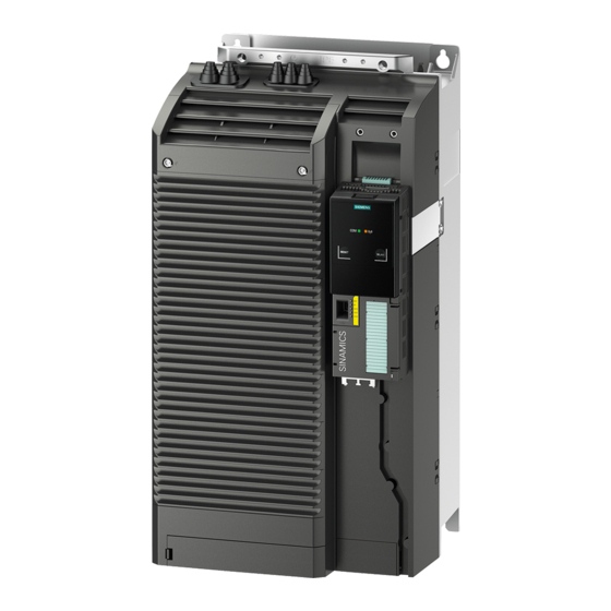
- Page 1 Power Module PM240P-2...
- Page 3 Fundamental safety instructions Introduction SINAMICS Installing Connecting SINAMICS G120 Power Module PM240P-2 Service and maintenance Technical data Hardware Installation Manual Spare parts and accessories Appendix 06/2020 A5E37800827C AD...
- Page 4 Note the following: WARNING Siemens products may only be used for the applications described in the catalog and in the relevant technical documentation. If products and components from other manufacturers are used, these must be recommended or approved by Siemens. Proper transport, storage, installation, assembly, commissioning, operation and maintenance are required to ensure that the products operate safely and without any problems.
-
Page 5: Table Of Contents
Table of contents Fundamental safety instructions ......................5 General safety instructions ....................... 5 Equipment damage due to electric fields or electrostatic discharge ........11 Warranty and liability for application examples ..............12 Security information ........................ 13 Residual risks of power drive systems ..................14 Introduction ............................ - Page 6 Table of contents Technical data ............................53 Electromagnetic compatibility - overview ................54 Ambient conditions ......................... 55 Overload capability of the converter ..................56 400 V converters ........................58 6.4.1 General data, 400 V converters ..................... 58 6.4.2 Specific data, 400 V converters ..................... 60 6.4.3 Current derating depending on the pulse frequency, 400 V converters ........
-
Page 7: Fundamental Safety Instructions
Fundamental safety instructions General safety instructions WARNING Electric shock and danger to life due to other energy sources Touching live components can result in death or severe injury. • Only work on electrical devices when you are qualified for this job. •... - Page 8 Fundamental safety instructions 1.1 General safety instructions WARNING Risk of electric shock and fire from supply networks with an excessively low impedance Excessively high short-circuit currents can lead to the protective devices not being able to interrupt these short-circuit currents and being destroyed, and thus causing electric shock or a fire.
- Page 9 Fundamental safety instructions 1.1 General safety instructions WARNING Electric shock due to unconnected cable shield Hazardous touch voltages can occur through capacitive cross-coupling due to unconnected cable shields. • As a minimum, connect cable shields and the conductors of power cables that are not used (e.g.
- Page 10 • Therefore, if you move closer than 20 cm to the components, be sure to switch off radio devices or mobile telephones. • Use the "SIEMENS Industry Online Support app" only on equipment that has already been switched off. Power Module PM240P-2...
- Page 11 Fundamental safety instructions 1.1 General safety instructions NOTICE Damage to motor insulation due to excessive voltages When operated on systems with grounded line conductor or in the event of a ground fault in the IT system, the motor insulation can be damaged by the higher voltage to ground. If you use motors that have insulation that is not designed for operation with grounded line conductors, you must perform the following measures: •...
- Page 12 Fundamental safety instructions 1.1 General safety instructions NOTICE Device damage caused by incorrect voltage/insulation tests Incorrect voltage/insulation tests can damage the device. • Before carrying out a voltage/insulation check of the system/machine, disconnect the devices as all converters and motors have been subject to a high voltage test by the manufacturer, and therefore it is not necessary to perform an additional test within the system/machine.
-
Page 13: Equipment Damage Due To Electric Fields Or Electrostatic Discharge
Fundamental safety instructions 1.2 Equipment damage due to electric fields or electrostatic discharge Equipment damage due to electric fields or electrostatic discharge Electrostatic sensitive devices (ESD) are individual components, integrated circuits, modules or devices that may be damaged by either electric fields or electrostatic discharge. NOTICE Equipment damage due to electric fields or electrostatic discharge Electric fields or electrostatic discharge can cause malfunctions through damaged... -
Page 14: Warranty And Liability For Application Examples
Fundamental safety instructions 1.3 Warranty and liability for application examples Warranty and liability for application examples Application examples are not binding and do not claim to be complete regarding configuration, equipment or any eventuality which may arise. Application examples do not represent specific customer solutions, but are only intended to provide support for typical tasks. -
Page 15: Security Information
Siemens’ products and solutions undergo continuous development to make them more secure. Siemens strongly recommends that product updates are applied as soon as they are available and that the latest product versions are used. Use of product versions that are no longer supported, and failure to apply the latest updates may increase customer’s exposure... -
Page 16: Residual Risks Of Power Drive Systems
Fundamental safety instructions 1.5 Residual risks of power drive systems Residual risks of power drive systems When assessing the machine- or system-related risk in accordance with the respective local regulations (e.g., EC Machinery Directive), the machine manufacturer or system installer must take into account the following residual risks emanating from the control and drive components of a drive system: 1. -
Page 17: Introduction
Introduction Overview The Power Modules belong to the modular family of SINAMICS G120 converters. A modular converter comprises Control Unit and Power Module. Depending on the power rating in frame sizes FSD … FSF, the following Power Module versions are supplied: 22 kW …... - Page 18 Introduction Component specification according to UL The components of the SINAMICS G120 product family are UL-certified. The certification is indicated on the products using the UL Listing Mark. If the converter is protected using semiconductor fuses, then the fuses must be installed in the same electrical cabinet as the converter itself.
-
Page 19: Installing
Fuse types: Technical data (Page 53) – Circuit breaker (https://support.industry.siemens.com/cs/ww/en/view/109750825) Converters for systems in the United States / Canada (UL/cUL) ● For a system configuration in conformance with UL/cUL, use the fuse types approved for UL/cUL, specified in the Technical data, or the circuit breakers under the following Internet address. - Page 20 Installing 3.1 Installation conditions ● The converters provide internal motor protection corresponding to UL61800-5-1. The protection threshold is 115 % of the converter full load current. When commissioning, you can adapt the motor overload protection using parameter p0640. ● Use suitable UL-listed (ZMVV) ring lugs to connect the power terminals of frame size FSF.
-
Page 21: Emc-Compliant Installation Of A Machine Or System
Installing 3.2 EMC-compliant installation of a machine or system EMC-compliant installation of a machine or system The converter is designed for operation in industrial environments where strong electromagnetic fields are to be expected. Reliable and disturbance-free operation is only ensured for EMC-compliant installation. To achieve this, subdivide the control cabinet and the machine or system into EMC zones: EMC zones Figure 3-1... -
Page 22: Control Cabinet
Installing 3.2 EMC-compliant installation of a machine or system 3.2.1 Control cabinet ● Assign the various devices to zones in the control cabinet. ● Electromagnetically uncouple the zones from each other by means of one of the following actions: – Side clearance ≥ 25 cm –... -
Page 23: Cables
Further information Additional information about EMC-compliant installation is available in the Internet: EMC installation guideline (http://support.automation.siemens.com/WW/view/en/60612658) 3.2.2 Cables Cables with a high level of interference and cables with a low level of interference are connected to the converter: ●... - Page 24 Installing 3.2 EMC-compliant installation of a machine or system Cable routing inside the cabinet ● Route the power cables with a high level of interference so that there is a minimum clearance of 25 cm to cables with a low level of interference. If the minimum clearance of 25 cm is not possible, insert separating metal sheets between the cables with a high level of interference and cables with a low level of interference.
- Page 25 Installing 3.2 EMC-compliant installation of a machine or system Routing cables outside the control cabinet ● Maintain a minimum clearance of 25 cm between cables with a high level of interference and cables with a low level of interference. ● Use shielded cables for the following connections: –...
-
Page 26: Electromechanical Components
Installing 3.2 EMC-compliant installation of a machine or system 3.2.3 Electromechanical components Surge voltage protection circuit ● Connect surge voltage protection circuits to the following components: – Coils of contactors – Relays – Solenoid valves – Motor holding brakes ● Connect the surge voltage protection circuit directly at the coil. ●... -
Page 27: Power Losses And Air Cooling Requirements
Installing 3.3 Power losses and air cooling requirements Power losses and air cooling requirements Cooling requirements To protect the components from overheating, the control cabinet requires a cooling air flow, which depends on the power loss of the individual components. Formula for calculating the cooling airflow: airflow [l/s] = power loss [W] * 0.86 / ΔT [K] Total of the power losses of the individual components. -
Page 28: Mounting The Power Modules
Installing 3.4 Mounting the Power Modules Mounting the Power Modules Protection against the spread of fire The device may be operated only in closed housings or in control cabinets with protective covers that are closed, and when all of the protective devices are used. The installation of the device in a metal control cabinet or the protection with another equivalent measure must prevent the spread of fire and emissions outside the control cabinet. -
Page 29: Sequence For Installing The Power Module
Installing 3.4 Mounting the Power Modules 3.4.1 Sequence for installing the Power Module During installation, comply with the sequence listed below. 1. Prepare the cabinet. 2. If you are using a Brake Relay or Safe Brake Relay: Install the Brake Relay on the rear side of the shield plate. 3. -
Page 30: Dimension Drawings And Drilling Dimensions
Installing 3.4 Mounting the Power Modules 3.4.2 Dimension drawings and drilling dimensions The following dimension drawings and drilling patterns are not to scale. Table 3- 1 Dimensions depend on the Control Unit (CU) and Operator Panel (OP) Frame Width Height [mm] Depth [mm] size [mm]... -
Page 31: Hoisting Gear
Installing 3.4 Mounting the Power Modules Table 3- 2 Drilling dimensions, cooling air clearances and fixing Frame Drilling dimensions [mm] Cooling air clearances [mm] Fixing / torque [Nm] size Bottom Front 4 x M5 / 6.0 4 x M6 / 10 4 x M8 / 25 The Power Module is designed for mounting without any lateral cooling air clearance. -
Page 32: Mounting The Shield Plate And Emc Connecting Bracket
Installing 3.4 Mounting the Power Modules 3.4.4 Mounting the shield plate and EMC connecting bracket Use the shield plate provided for strain relief of the line and motor cable – as well as the shield support for the motor cable. If you are using the converter without filter, then you do not require the EMC connecting bracket. - Page 33 Installing 3.4 Mounting the Power Modules Procedure - FSF: Proceed as follows to mount the EMC connecting bracket and the shield plate: ① 1. Attach the EMC connecting bracket to the shield plate ② 2. Screw the shield module to the converter using three screws, as shown in the diagram.
-
Page 34: Supplementary Components
Installing 3.5 Supplementary components Supplementary components Depending on the particular application, additional components may be required for your system. Information about additional components is provided in the following Sections: Connection overview (Page 41) Optional accessories (Page 80) Power Module PM240P-2 Hardware Installation Manual, 06/2020, A5E37800827C AD... -
Page 35: Connecting
To protect against indirectly touching part of the motor circuit of a converter and to automatically shut down in the case of a fault according to DIN EN 60364-4-41 (VDE 0100- 410). (http://support.automation.siemens.com/WW/view/en/103474630) WARNING Electrical shock due to inadequate touch protection Due to faulty contact protection, the power connections of the converter may be openly accessible. - Page 36 300 mA. Connect the RCCB in series with the overcurrent protective devices. ● For converters with rated input currents ≤ 160 A referred to LO, use a Siemens residual current device RCD520B (3VA9113-0RL21) mounted onto a Siemens molded case circuit breaker (series 3VA1).
- Page 37 Connecting ● For converters with rated input currents > 160 A referred to LO, use a Siemens modular RCCB device (MRCD type B 5SV8111-4KK) with a current transformer (5SV870.-2K), a circuit breaker (series 3VA1) and a trip element (3VA9988-0BL30). Figure 4-1 MRCD ●...
-
Page 38: Permissible Line Supplies
Connecting 4.1 Permissible line supplies Permissible line supplies The converter is designed for the following line supplies according to IEC 60364-1 (2005). ● TN system ● TT system ● IT system Restrictions for installation altitudes above 2000 m Above an installation altitude of 2000 m, the permissible line supplies are restricted. Restrictions for special ambient conditions (Page 69) General requirements on line supply The plant builder or machine manufacturer must ensure for operation with rated current I... -
Page 39: Tt Line System
Connecting 4.1 Permissible line supplies 4.1.2 TT line system In a TT line system, the transformer ground- ing and the installation grounding are inde- pendent of one another. There are TT line supplies where the neutral conductor N is either transferred – or not. Note Operation in IEC or UL systems For installations in compliance with IEC, operation on TT line systems is permissible. -
Page 40: It System
Connecting 4.1 Permissible line supplies 4.1.3 IT system In an IT line system, all of the conductors are insulated with respect to the PE protective conductor – or connected to the PE protec- tive conductor through an impedance. There are IT systems with and without trans- fer of the neutral conductor N. -
Page 41: Requirements For The Protective Conductor
Connecting 4.1 Permissible line supplies 4.1.4 Requirements for the protective conductor Overview A high leakage current flows through the protective conductor in converter operation. The protective conductor of the converter must not be interrupted for safe touch protection in converter operation. This primarily results in requirements for the minimum conductor cross-section of the protective conductor. - Page 42 Connecting 4.1 Permissible line supplies ① ④ The minimum cross-section of the protective conductor … depends on the cross- section of the line or motor feeder cable: ● Line or motor feeder cable ≤ 16 mm ⇒ Minimum cross-section of the protective conductor = cross-section of the line or motor feeder cable ●...
-
Page 43: Connecting The Line And Motor Cable At The Converter
Connecting 4.2 Connecting the line and motor cable at the converter Connecting the line and motor cable at the converter 4.2.1 Connection overview Figure 4-2 Block diagram PM240P-2 Figure 4-3 Connection overview Connect cables at the converter so that they are EMC compliant Attach the cable tie holders to the Power Module as shown to the left in the diagram before you establish the connections. -
Page 44: Length Of The Motor Cable
Connecting 4.2 Connecting the line and motor cable at the converter 4.2.2 Length of the motor cable Always dimension the motor cable so that the ohmic losses are less than 5 % of the converter power rating. The permissible length of the motor cable also depends on the quality of the motor cable and the converter pulse frequency. -
Page 45: Converter Terminals
Connecting 4.2 Connecting the line and motor cable at the converter 4.2.3 Converter terminals Table 4- 2 Connection, cross-section and tightening torque for PM240P-2 Power Modules Converter Connection Cross-section, tightening torque Stripped insulation Metric Imperial length Line supply, Screw-type termi- 10 …... - Page 46 Connecting 4.2 Connecting the line and motor cable at the converter In addition, for frame sizes FSD and FSE, release the two terminal screws on the connections for the motor and remove the dummy plug. For frame size FSF you must breakout the openings from the connection cover for the power connections.
-
Page 47: Sto Via Power Module Terminals
Connecting 4.3 STO via Power Module terminals STO via Power Module terminals Description The "Safe Torque Off" (STO) safety function can be implemented via terminals on the power modules of frame sizes FSD … FSF. Figure 4-6 Terminals and switches for the "STO via power module terminals" function The two switches have the following function: ●... - Page 48 Connecting 4.3 STO via Power Module terminals Procedure 1. Connect the cable to select STO at terminals STO_A and STO_B on the front of the power module. 2. Tighten the screws of the terminals with a torque of 0.2 Nm (2 lbf in). 3.
-
Page 49: Connecting The Motor To The Converter In A Star Or Delta Connection
Connecting 4.4 Connecting the motor to the converter in a star or delta connection Connecting the motor to the converter in a star or delta connection Overview Standard induction motors up to a rated power of approximately 3 kW are usually connected in star/delta connection (Y/Δ) at 400 V/230 V. - Page 50 Connecting 4.4 Connecting the motor to the converter in a star or delta connection Power Module PM240P-2 Hardware Installation Manual, 06/2020, A5E37800827C AD...
-
Page 51: Service And Maintenance
• Only commission the following persons to repair the converter: – Siemens customer service – A repair center that has been authorized by Siemens – Specialist personnel who are thoroughly acquainted with all the warnings and operating procedures contained in this manual. -
Page 52: Maintenance
Note The actual maintenance intervals depend on the installation and operating conditions. Siemens offers its customers support in the form of service contracts. For further information, contact your Siemens regional office or sales office. Power Module PM240P-2... -
Page 53: Replacing A Fan
Service and maintenance 5.2 Replacing a fan Replacing a fan Service life of the fan The average service life of the fan is 40,000 hours. In practice, however, the service life may deviate from this value. Especially a dusty environment can block up the fan. The fan must be replaced in good time to ensure that the converter is ready for operation. - Page 54 Service and maintenance 5.2 Replacing a fan The fan module is installed at the top. Procedure ① ② 1. Remove the fan module from the Power Module in steps as shown in the diagram. Use a screwdriver if necessary. 2. Install the new fan module in inverse sequence. By inserting the fan module, you establish the electrical connection between the converter and fan module.
-
Page 55: Technical Data
The fuses listed in the following tables are examples of suitable fuses. Additional components for branch protection are available in the Internet: Branch protection and short-circuit strength according to UL and IEC (https://support.industry.siemens.com/cs/ww/en/view/109750825) Power Module PM240P-2 Hardware Installation Manual, 06/2020, A5E37800827C AD... -
Page 56: Electromagnetic Compatibility - Overview
Technical data 6.1 Electromagnetic compatibility - overview Electromagnetic compatibility - overview Electromagnetic compatibility according to EN61800-3 Property Version Interference immunity The converters are suitable for use in the first and second industrial environments Interference emission - Category C2 for converters with integrated radio interference suppression filter second environment Category C2 for converters without filter with optional external radio interference suppres-... -
Page 57: Ambient Conditions
Technical data 6.2 Ambient conditions Ambient conditions Property Version Ambient conditions for transport in the transport packaging Climatic ambient conditions - 40 °C … + 70 °C, according to Class 2K4 to EN 60721-3-2:1997 maximum humidity 95% at 40 °C Mechanical ambient condi- Shocks and vibrations permissible according to 2M3 to IEC 60721-3-2:1997 tions... -
Page 58: Overload Capability Of The Converter
If not specified otherwise, the power and current data in the technical data always refer to a load cycle according to Low Overload. We recommend using the "SIZER" engineering software to select the converter. You can find additional information about SIZER on the Internet: Download Sizer (http://support.automation.siemens.com/WW/view/en/10804987/130000) Power Module PM240P-2 Hardware Installation Manual, 06/2020, A5E37800827C AD... - Page 59 Technical data 6.3 Overload capability of the converter Load cycles and typical applications: "Low Overload" load cycle "High Overload" load cycle The "Low Overload" load cycle assumes a The "High Overload" load cycle permits uniform base load with low requirements dynamic accelerating phases at a reduced placed on brief accelerating phases.
-
Page 60: 400 V Converters
Short-circuit current rating ≤ 100 kA rms (SCCR) and branch pro- Branch protection and short-circuit strength according to UL and IEC tection (https://support.industry.siemens.com/cs/ww/en/view/109479152) Braking methods DC braking, compound braking Degree of protection ac- IP20 Must be installed in a control cabinet... - Page 61 Technical data 6.4 400 V converters Current and power limiting depending on the line voltage Power Module PM240P-2 Hardware Installation Manual, 06/2020, A5E37800827C AD...
-
Page 62: Specific Data, 400 V Converters
47 A 62 A HO base load output current 38 A 45 A 60 A Siemens fuse according to IEC/UL 3NE1820-0 / 80 A 3NE1021-0 / 100 A 3NE1021-0 / 100 A Fuse according to IEC/UL, Class J 70 A... - Page 63 154 A 189 A HO base load output current 110 A 145 A 178 A Siemens fuse according to IEC/UL 3NE1225-0 / 200 A 3NE1227-0 / 250 A 3NE1230-0 / 315 A Fuse according to IEC/UL, Class J 200 A...
-
Page 64: Current Derating Depending On The Pulse Frequency, 400 V Converters
Technical data 6.4 400 V converters 6.4.3 Current derating depending on the pulse frequency, 400 V converters Article number LO base load output current [A] power [kW] Pulse frequency [kHz] 6SL3210-1RE24-5 . L0 38.3 31.5 22.5 20.3 6SL3210-1RE26-0 . L0 6SL3210-1RE27-5 . -
Page 65: Converters
Short-circuit current rating ≤ 100 kA rms (SCCR) and branch protec- Branch protection and short-circuit strength according to UL and IEC tion (https://support.industry.siemens.com/cs/ww/en/view/109479152) Braking methods DC braking, compound braking Degree of protection ac- IP20; must be installed in a control cabinet... -
Page 66: Specific Data, 690 V Converters
14 A 20 A HO base load output current 11 A 14 A 19 A Siemens fuse according to IEC/UL 3NE1815-0 / 25 A 3NE1815-0 / 25 A 3NE1803-0 / 35 A Fuse according to IEC/UL, Class J 20 A... - Page 67 HO base load input current 44 A 54 A HO base load output current 42 A 52 A Siemens fuse according to IEC/UL 3NA1820-0 / 80 A 3NE1820-0 / 80 A Fuse according to IEC/UL, Class J 80 A 80 A Power loss without filter 1.00 kW...
- Page 68 HO base load power 110 kW HO base load input current 122 A HO base load output current 115 A Siemens fuse according to IEC/UL 3NE1225-0 / 200 A Fuse according to IEC/UL, Class J 200 A Power loss without filter 2.56 kW Power loss with filter 2.59 kW...
-
Page 69: Current Derating Depending On The Pulse Frequency, 690 V Converters
Technical data 6.5 690 V converters 6.5.3 Current derating depending on the pulse frequency, 690 V converters Article number LO base load output current [A] power [kW] Pulse frequency [kHz] 6SL3210-1RH21-4 . L0 6SL3210-1RH22-0 . L0 11.4 6SL3210-1RH22-3 . L0 13.8 6SL3210-1RH22-7 . -
Page 70: Safety Integrated
Technical data 6.6 Safety Integrated Safety Integrated Property Explanation Standards STO fulfils the requirements of the following standards: SIL 3 according to IEC61508, part 1 to 3 (2010) • PL e according to IEC61800-5-2 (2016) • Category 3 according to ISO13849 part 1 (2015) •... -
Page 71: Restrictions For Special Ambient Conditions
Technical data 6.7 Restrictions for special ambient conditions Restrictions for special ambient conditions Maximum current at low speeds NOTICE Overheating the converter due to unsuitable load Loading the converter with a high output current at the same time as a low output frequency can cause the current-conducting components in the converter to overheat. - Page 72 Technical data 6.7 Restrictions for special ambient conditions Current reduction as a function of the installation altitude and ambient temperature At installation altitudes above 1000 m the permissible converter output current is reduced. Figure 6-3 Current reduction as a function of the installation altitude At installation altitudes above 1000 m, you can compensate the permissible converter output current to a certain extent using the ambient temperature.
- Page 73 Technical data 6.7 Restrictions for special ambient conditions Permissible line supplies dependent on the installation altitude ● For installation altitudes ≤ 2000 m above sea level, it is permissible to connect the converter to any of the line supplies that are specified for it. ●...
-
Page 74: Electromagnetic Compatibility Of Variable-Speed Drives
Technical data 6.8 Electromagnetic compatibility of variable-speed drives Electromagnetic compatibility of variable-speed drives EMC (electromagnetic compatibility) means that the devices function satisfactorily without interfering with other devices and without being disrupted by other devices. EMC applies when the emitted interference (emission level) and the interference immunity are matched with each other. -
Page 75: Converter Applications
- and are not operated in the general public domain. For an EMC-compliant installation, observe the information provided in the Configuration manual:EMC installation guideline (http://support.automation.siemens.com/WW/view/en/60612658). The devices described there are intended for operation in the first and second environments. Conditions for operation in the respective environment are subsequently listed. -
Page 76: Operation In The First Environment
Further information on unfiltered devices can be found on the Internet: Compliance with EMC limits with unfiltered devices (https://support.industry.siemens.com/cs/ww/en/view/109750634) Interference emission - operation in the second environment, Category C4 When connected to IT line supplies, only filtered converters are permissible. Use external filters without capacitors with respect to ground to limit symmetrical interference emission. - Page 77 Technical data 6.8 Electromagnetic compatibility of variable-speed drives ● Converters with an LO base load input current > 16 A and ≤ 75 A The drive system is in compliance with IEC/EN 61000-3-12 under the following precondition: – Power Module FSD, input voltage 380 … 480 V 3 AC: A line reactor is not required –...
-
Page 78: Harmonic Currents
Technical data 6.8 Electromagnetic compatibility of variable-speed drives 6.8.2 Harmonic currents Table 6- 12 Typical harmonic currents (%) of the converter Converter Harmonic number 11th 13th 17th 19th 23rd 25th FSD … FSF, 400 V FSD … FSF, 690 V Values referred to the LO input current 6.8.3 Harmonics at the power supply connection point according to IEC 61000-2-2... -
Page 79: Emc Limit Values In South Korea
You can find additional information about EMC-compliant configuration of the plant or system on the Internet: EMC installation guideline (http://support.automation.siemens.com/WW/view/en/60612658) The final statement on compliance with the applicable standard is given by the respective label attached to the individual device. -
Page 80: Service Life
Technical data 6.9 Service life Service life The PM240P-2 is designed to have a service life of 10 years under the following conditions: ● Nominal load at 40 °C: 4000 h/y ● Idle time or standby at 20 °C: 4000 h/y ●... -
Page 81: Spare Parts And Accessories
*) Included in the scope of delivery of the converter Spare parts through Spares on Web Spares on Web (https://www.automation.siemens.com/sow) When you enter the article number and serial number of your device, you obtain a spare parts list current at the time of your inquiry. -
Page 82: Optional Accessories
Spare parts and accessories 7.2 Optional accessories Optional accessories Which components are available? ● Shield plate at the top ● Line harmonics filter ● Motor holding brake controlled using a Brake Relay or Safe Brake Relay ● Sine-wave filter ● Output reactor Connection components Connection overview for the electrical components Connection overview (Page 41). -
Page 83: Motor Holding Brake
Spare parts and accessories 7.2 Optional accessories 7.2.2 Motor holding brake The converter uses the Brake Relay to control the motor holding brake. Two types of Brake Relay exist: ● The Brake Relay controls the motor holding brake ● The Safe Brake Relay controls a 24 V motor holding brake and monitors the brake control for short-circuit or cable breakage. -
Page 84: Mounting And Connecting The Brake Relay
Spare parts and accessories 7.2 Optional accessories 7.2.2.2 Mounting and connecting the Brake Relay Mounting the Brake Relay Mount the Brake Relay at the rear of the shield plate. Mount it before you mount the shield plate. Mounting the shield plate and EMC connecting bracket (Page 30) Brake Relay Safe Brake Relay Power Module PM240P-2... -
Page 85: Line Harmonics Filter
Spare parts and accessories 7.2 Optional accessories Connecting the Brake Relay to the converter The connector for the Brake Relay is located at the front of the Power Module. Lay the cable harness for the Brake Relay in the cable routing. 7.2.3 Line harmonics filter The line harmonics filters reshape the distorted current back to the desired sinusoidal... - Page 86 Spare parts and accessories 7.2 Optional accessories Assignment tables Power Module, 400 V Line harmonics filter Frame Article number Power [kW] Article number size 6SL3210-1RE24-5 . L0 UAC:FN344022115E2FAJRX 6SL3210-1RE26-0 . L0 UAC:FN344030115E2FAJRX 6SL3210-1RE27-5 . L0 UAC:FN344037115E2FAJRX 6SL3210-1RE28-8 . L0 UAC:FN344045115E2FAJRX 6SL3210-1RE31-1 .
- Page 87 Spare parts and accessories 7.2 Optional accessories Dimensions, drilling patterns, and technical data Article number Weight Dimensions [mm] Drilling patterns Power connections [kg] [mm] ∅ [AWG / PE / lbf.in] torque [Nm] UAC:FN344022115E2FAJRX 11 10 ... 50 / 1/0 ... 8 / M8 / 14 UAC:FN344030115E2FAJRX 70.8...
-
Page 88: Sine-Wave Filter
Spare parts and accessories 7.2 Optional accessories 7.2.4 Sine-wave filter The sine-wave filter limits the voltage gradient and the capacitive recharging currents which generally occur in converter operation. Therefore, when a sine-wave filter is used, longer screened motor cables are possible and the motor lifetime reaches the same values which are achieved when the motor is connected directly to the mains. - Page 89 Spare parts and accessories 7.2 Optional accessories Dimensions [mm] and drilling patterns Sine-wave filter Overall dimensions (mm) Drilling dimensions (mm) Fixing/torque Weight (Nm) (kg) 6SL3202-0AE24-6SA0 90.5 4 x M6 / 7 6SL3202-0AE26-2SA0 90.5 4 x M6 / 7 6SL3202-0AE28-8SA0 100.5 4 x M8 / 13 6SL3202-0AE31-5SA0 156.5...
- Page 90 Spare parts and accessories 7.2 Optional accessories Sine-wave filter Overall dimensions (mm) Drilling dimensions (mm) Fixing/torque Weight (Nm) (kg) 6SL3000-2CE32-3AA0 6 x M10 / 20 Technical data Article number (W) Connection Degree of loss protection Power Module Motor 6SL3202-0AE24-6SA0 Screw terminals 25 … 50 mm IP00 6SL3202-0AE26-2SA0 Screw terminals 25 …...
-
Page 91: Output Reactor
Spare parts and accessories 7.2 Optional accessories 7.2.5 Output reactor Output reactors reduce the voltage stress on the motor windings and the load placed on the converter as a result of capacitive recharging currents in the cables. When using a output reactor, observe the following restrictions: ●... - Page 92 Spare parts and accessories 7.2 Optional accessories Clearances to other devices Keep shaded areas free of any devices and components. Minimum clearances of the output reactor to other devices, space-saving mounting examples Power Module PM240P-2 Hardware Installation Manual, 06/2020, A5E37800827C AD...
- Page 93 Spare parts and accessories 7.2 Optional accessories Dimensions, drilling patterns and weights for FSD … FSF converters Figure 7-1 Dimensions and drilling patterns Table 7- 1 Dimensions and weights Article number Induct- Overall dimensions Drilling dimensions Fix- Weight ance [mm] [mm] ing/torque [kg]...
- Page 94 Spare parts and accessories 7.2 Optional accessories Table 7- 3 Assignment table for 690 V Power Modules Power Module Output reactor Frame size Article number Power [kW] Article number 6SL3210-1RH21-4 . L0 JTA:TEU 2532-0FP00-4EA0 6SL3210-1RH22-0 . L0 6SL3210-1RH22-3 . L0 18.5 6SL3210-1RH22-7 .
-
Page 95: Appendix
Manuals and technical support A.1.1 Manuals for your converter Manuals with additional information that can be downloaded: ● Power Module Installation Manual (https://support.industry.siemens.com/cs/ww/de/ps/13224) Installing Power Modules, reactors and filters. Technical specifications, maintenance (this manual) ● CU230P-2 operating instructions (https://support.industry.siemens.com/cs/ww/en/view/109478827) Commissioning the converter ●... - Page 96 ● "Safety Integrated" function manual (https://support.industry.siemens.com/cs/ww/en/view/109751320) Configuring PROFIsafe. Installing, commissioning and operating fail-safe functions of the frequency converter. ● CU230P-2 List Manual (https://support.industry.siemens.com/cs/ww/en/view/109477248) Parameter list, alarms and faults. Graphic function diagrams ● CU240B/E-2 List Manual (https://support.industry.siemens.com/cs/ww/en/view/109477251) Parameter list, alarms and faults. Graphic function diagrams ●...
-
Page 97: Configuring Support
Catalog Ordering data and technical information for the converters SINAMICS G. Catalogs for download or online catalog (Industry Mall): All about SINAMICS G120 (www.siemens.com/sinamics-g120) SIZER The configuration tool for SINAMICS, MICROMASTER and DYNAVERT T drives, motor starters, as well as SINUMERIK, SIMOTION controllers and SIMATIC technology... -
Page 98: Product Support
A.1 Manuals and technical support A.1.3 Product Support Overview You can find additional information about the product on the Internet: Product support (https://support.industry.siemens.com/cs/ww/en/) This URL provides the following: ● Up-to-date product information (product announcements) ● FAQs ● Downloads ● The Newsletter contains the latest information on the products you use. -
Page 99: Directives And Standards
Specification for semiconductor process equipment voltage drop immunity The converters comply with the requirements of standard SEMI F47-0706. Quality systems Siemens AG employs a quality management system that meets the requirements of ISO 9001 and ISO 14001. Power Module PM240P-2... - Page 100 ● EC Declaration of Conformity: (https://support.industry.siemens.com/cs/ww/en/view/58275445) ● Certificates for the relevant directives, prototype test certificates, manufacturers declarations and test certificates for functions relating to functional safety ("Safety Integrated"): (http://support.automation.siemens.com/WW/view/en/22339653/134200) ● Certificates of products that were certified by UL: (http://database.ul.com/cgi- bin/XYV/template/LISEXT/1FRAME/index.html) ●...
-
Page 101: Abbreviations
Appendix A.3 Abbreviations Abbreviations Abbreviation Explanation Alternating current Communauté Européenne Control Unit Direct current Digital input DIP switch DIP switches are small switches, found mostly on PBCs, for making basic device settings Digital output Equivalent circuit diagram European Economic Community ELCB Earth leakage circuit breaker Electromagnetic compatibility (EMC) - Page 102 Appendix A.3 Abbreviations Power Module PM240P-2 Hardware Installation Manual, 06/2020, A5E37800827C AD...
-
Page 103: Index
Index 87 Hz characteristic, 47, 47 Getting Started, 93 Air barrier, 25 Hardware Installation Manual, 93 Harmonic currents, 76 High Overload, 57 Hotline, 96 Base load, 56 Base load input current, 56 Base load output current, 56 Base load power, 56 Industry Mall, 95 Brake Relay, 81 Installation altitude, 71... - Page 104 Index Power distribution systems, 36 Protective conductor, 36 Questions, 96 Safe Brake Relay, 81 Safety notes Electrical installation, 33 Service life of the fan, 51 SIZER, 95 Standards EN 61800-3, 97 Star connection (Y), 47 Support, 96 TN system, 36 TT system, 36 Power Module PM240P-2 Hardware Installation Manual, 06/2020, A5E37800827C AD...