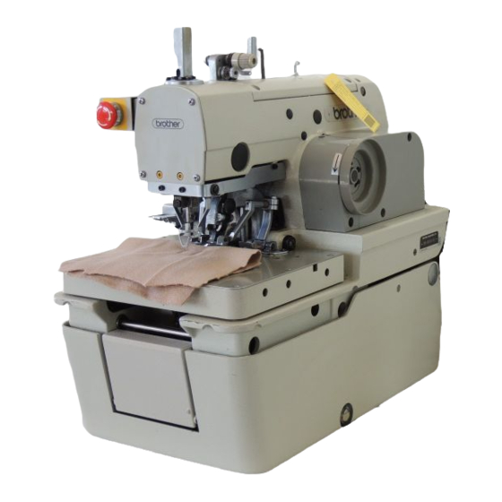
Brother RH-981A Service Manual
Electronic eyelet button holer
Hide thumbs
Also See for RH-981A:
- Parts manual (109 pages) ,
- Instruction manual (89 pages) ,
- Specifications (8 pages)

Related Manuals for Brother RH-981A


Summary of Contents for Brother RH-981A
- Page 1 RH-981A SERVICE MANUAL Please read this manual before using the machine. Please keep this manual within easy reach for quick reference. ELECTRONIC EYELET BUTTON HOLER...
- Page 2 This service manual is intended for RH-981A; be sure to read the RH-981A instruction manual before this manual. Carefully read the “SAFETY INSTRUCTIONS” below and the whole of this manual to understand this product before you start maintenance. As a result of research and improvements regarding this product, some details of this manual may not be the same as those for the product you purchased.
- Page 3 Furthermore, do not excessively bend the cords or secure them too Contact your Brother dealer or a qualified electrician firmly with staples, otherwise there is the danger for any electrical work that may need to be done.
- Page 4 Ask your Brother dealer or a qualified electrician to Use only the proper replacement parts as carry out any maintenance and inspection of the specified by Brother.
- Page 5 The following warning labels appear on the sewing machine. Please follow the instructions on the labels at all times when using the machine. If the labels have been removed or are difficult to read, please contact your nearest Brother dealer. Safety devices...
-
Page 6: Table Of Contents
4-9. Fine adjustment of knife position......54 3-8-1. Eliminating end play of the thread take-up 4-10.Adjusting the sideways movement on the arm ...........27 of the cutter lever..........55 3-8-2. Applying grease to the ends of the thread 4-11.Adjusting the height of the throat plate.....55 take-up spring..........27 RH-981A... - Page 7 4-24.Adjusting the position of the lower thread presser (-02, -52 specifications) ........75 4-25.Adjusting the rotating centers of the needle bar and the looper base .....76 4-26.Adjusting the needle bar stop position.....77 RH-981A...
- Page 8 RH-981A...
-
Page 9: Mechanical Descriptions
2. When the pulley (5) rotates in the direction of the arrow, its motion is transmitted to the upper shaft timing pulley (6), the timing belt (7), and the lower shaft tension pulley (8), and the lower shaft (9), causing the lower shaft cam (10) to turn in the direction of the arrow. RH-981A... -
Page 10: Needle Bar Mechanism
2. The thread take-up cam (4), which is attached to the needle bar gear (3), moves the thread take-up (6) via the thread take-up cam roller (5). 3. The thread take-up cam roller (5) is always kept in contact with the cam (4) by the thread take-up spring (7) attached to the thread take-up (6). RH-981A... -
Page 11: Zigzag Mechanism
3. When the vertical shaft T pulley U assembly (7), which is attached to the driving looper shaft assembly (5), rotates, the motion is transmitted to timing belt U (8), and the needle bar block assembly (9) that rotates the needle bar (10). RH-981A... -
Page 12: Feed Mechanism
2. The Y-timing belt (18) is secured by the Y-driving shaft holder (19) and the belt holder (20), and that moves the Y shaft (21). 3. The linear bush (23), which is fitted in the ball bearing (22), is fitted in the Y-guide shaft (24) to move the feed bar (13) in the Y direction. RH-981A... -
Page 13: Work Clamp Mechanism
* The work clamp mechanism is activated by independently-operated left and right cylinders, that can equalize the pressure of the work clamp. The pressure of the work clamp is always applied to the material equally even when the material thickness changes. RH-981A... -
Page 14: Cloth Opener Mechanism
6. When the cylinder 16 X 15 assembly (2) is not pressurized, the work clamp plate (12) is moved in the direction of b by the opening spring (17). At this time, the stopper (13) of the work clamp plate (12) makes contact with the stopper plate (18). * The c indicates the movement of the work clamp plate (12). RH-981A... -
Page 15: Cutter Mechanism
3. When the lower shaft cam (4) rotates in the direction of the arrow, the looper link assembly (2) is rocked via the looper cam roller (3). 4. The looper driving shaft (6) moves up and down due to the motion of the looper link assembly (2). RH-981A... -
Page 16: 1-11.Spreader Mechanism
2. When the lower shaft cam (4) rotates in the direction of the arrow, the spreader cam lever (2) is rocked via the spreader cam roller (3). 3. The spreader link shaft (7) moves up and down due to the motion of the spreader cam lever (2). RH-981A... -
Page 17: 1-12.Double Chain Stitch Looper Mechanism
(5) secured to the loop base (4) regarded as the pivot. 3692Q 3693Q 3. The rocking motions of the LS-holder bracket (6) and the spreader differential cam (10) cause spreader L (11) to rock. 4. In the same way, spreader R (12) is rocked. RH-981A... -
Page 18: Disassembly
Use only the proper replacement parts as result in injury. specified by Brother. Be sure to wear protective goggles and gloves If any safety devices have been removed, be when handling the lubricating oil and grease,... -
Page 19: Feed Mechanism
(6), including the Y motor unit. 2-3. Lubrication mechanism Hole Oil tank 3699Q 1. Remove the wick supports (1) and (2). 2. Remove the wicks (3) and (4) from the hole. 3. Remove the two screws (5) and wick support L (6). RH-981A... -
Page 20: Looper And Spreader Mechanisms
4. Loosen the two set screws (10) of the set collar (9) and the two set screws (11), and remove the looper link support shaft (12). 5. Slide the lower shaft cam (13) in the direction of the arrow, and remove the looper link (14). RH-981A... -
Page 21: Needle Bar Rotating Mechanism
4. Remove the four bolts (9) and the motor base (10). 5. Loosen the bolt (12) of the vertical shaft T-pulley U assembly (11) and the two set screws (14) of the set collar (13). 6. Remove the driving looper shaft assembly (15) downward. RH-981A... -
Page 22: Looper Base Mechanism
Loosen the screw (10) of the looper pulley assembly (9), and remove the looper base (11) in the direction of the arrow. * Be careful not to drop the two ball bearings (12) when removing the looper pulley assembly (9). RH-981A... -
Page 23: Needle Bar, Thread Take-Up, And Zigzag Mechanisms
2. DISASSEMBLY 2-7. Needle bar, thread take-up, and zigzag mechanisms 3708Q 3709Q 3710Q 3711Q RH-981A... - Page 24 1. Remove the spring (39) and the two rubber caps (40). 2. Loosen the two set screws (41) and the two set screws (43) of the set collar (42), and remove the support shaft (44). 3. Remove the thread take-up lever assembly (45). RH-981A...
-
Page 25: Knife Pipe Assembly
1. Loosen the two set screws (2) of the lower shaft tension pulley assembly (1). 2. Loosen the two set screws (4) of the lower shaft cam (3). 3. Loosen the two set screws (6) of the set collar (5). 4. Remove the cam shaft (7) in the direction of the arrow. RH-981A... -
Page 26: 2-10.Synchronizer Mechanism
2. Loosen each set screw (2 each) of the needle bar gear (3), the zigzag cam (4), and the upper shaft tension pulley assembly (5). 3. Pull the upper shaft (6) in the direction of the pulley to remove it. The upper shaft unit will come off. RH-981A... -
Page 27: 2-12.Cutter Mechanism
7. Loosen the two set screws (19), and remove the cylinder support shaft (20) and the cutter cylinder (21). 2-13. Zigzag fork mechanism 3717Q 1. Remove the two nuts (1), and the zigzag connection rod assembly (2). 2. Remove the nut (3), the zigzag fork support pin (4), and the zigzag fork (5). RH-981A... -
Page 28: Assembly
Use only the proper replacement parts as in injury. specified by Brother. Be sure to wear protective goggles and gloves If any safety devices have been removed, be when handling the lubricating oil and grease, so... -
Page 29: Cutter Mechanism
8. Pass link shaft B (17) with its slit facing the right, through the slot of link A (5), and the hole in the cutter lever (12), and tighten the set screw (18). 9. Wind the wick (19) around the right of link C (4), and insert the end of the wick into the lubrication hole in the cylinder rod shaft (9). RH-981A... -
Page 30: Upper Shaft Mechanism
(6) by tightening the set screw which comes first when rotated in the rotation direction, against the screw flat. Then tighten the other set screw. 7. Temporarily tighten the pulley with its screw flat facing the front. RH-981A... -
Page 31: Lower Shaft Mechanism
(3) are as shown in figure 1, loop the timing belt over the lower shaft tension pulley assembly (3). 3-4-1. Adjusting the timing belt Use a screwdriver or similar tool to press the notch of the tension pulley arm assembly (1) with a force of 39.2 N, and attach the tension pulley assembly. 3723Q RH-981A... -
Page 32: Upper Thread Trimmer Mechanism
(2) so that the clearance with the bed is 11 mm. 2. Lower the thread trimmer lever hammer (1), and adjust the set screw (3) so that the clearance with the bed is 6 mm. 3726Q RH-981A... -
Page 33: Knife Pipe And The Knife Bracket
(2). 3727Q Knife bracket Insert a bar with a diameter of 4 mm into the hole (1) in the knife bracket to fix the knife bracket position, and tighten the bolts (2) to (6). 3728Q RH-981A... -
Page 34: Driving Gear Shaft Mechanism
* The driving gear shaft (1) should be turned in the direction where its lubrication hole is moving upward. 2. While pressing the set screw collar (2) toward the pulley so that the driving gear shaft (1) has no end play, tighten the two set screws (4). RH-981A... -
Page 35: Needle Bar, Thread Take-Up, And Zigzag Mechanisms
(3) and the spring hook (4). 3732Q 3-8-3. Eliminating end play of the needle bar driving lever Adjust the position of the set screw collar (2) to eliminate end play of the needle bar driving lever assembly (1). 3733Q RH-981A... -
Page 36: 3-8-4.Eliminating End Play Of The Driving Rod
(4) as shown in the above figure, and pass the zigzag rock shaft (5) through the arm from the right. At this time, insert a wedge or similar tool into the split of the zigzag crank (1) for easier adjustment. Note: Do not fail to attach the washer (3). RH-981A... -
Page 37: 3-8-7.Eliminating End Play Of The Zigzag Lever
(2), pass the wick (3) through the needle bar driving lever assembly (1), and fit the cap (4). 2. Attach the needle bar level feed link (5) to the needle bar yoke (2) vertically, and turn it 90°. 3738Q RH-981A... -
Page 38: 3-8-9.Attaching The Needle Bar Bush U And The Needle Bar
5. Insert the needle bar felt (14), the needle bar clamp (5), the needle bar level feed link (16), the needle bar block clamp (17), the needle bar level feed link (18), and the needle bar block collar (19), through the needle bar assembly (13) in this order. 3740Q RH-981A... -
Page 39: Eliminating End Play Of The Needle Bar Block
(4) using the two set screws (3) so that the needle bar can move smoothly. Note: Position the needle bar assembly (4) so that the holder plate A (5) will face the front when the set screws (3) are facing the front. 3743Q RH-981A... -
Page 40: Attaching The Needle Bar Block Assembly
2. Set the height of the needle bar (2) to approx. 62 mm, eliminate end play between the two needle bar clamps (3) and the needle bar level feed link (1), and tighten the two screws (4). Approx. 62 mm 3746Q RH-981A... -
Page 41: Looper Base
(8). Align the reference line (10) with the top surface of the spreader link base (9), and tighten the screw (11). 4. Attach the L-tension stud (12), the thread guide discs (13), pre-tension spring B (14), and the tension nut (15) to the looper base (1). RH-981A... -
Page 42: 3-10.Needle Bar Rocking Mechanism
(1) through timing belt U (10). 4. Attach the tension pulley arm U assembly (11) while it is being pulled by a force of 19.6 N. * Deflection in the center of span: 3 ± 0.5 mm when 4.9 N is applied. 3749Q RH-981A... -
Page 43: Needle Bar Rocking Mechanism
Adjusting the timing belt tension Attach the timing belt D while the tension pulley arm D assembly is being pulled by a force of 68.6 N. * Deflection in the center of span: 6 ± 0.5 mm when 4.9 N is applied. RH-981A... - Page 44 2. Align the match mark in the looper base (3) with that in the bed, as shown in the figure. 3. Orient the needle bar gear (4) in the direction shown in the figure, and align it with gear support B (5). 4. Tighten the bolt (2) of the vertical shaft T-pulley U assembly (1). RH-981A...
-
Page 45: 3-11.Looper And Spreader Machanisms
2. Wind the wick (4) around the boss of the looper link (3). Be sure to pass the two wicks (5) under the wick (4). 3. Wind the wick (6) around the spreader driving lever (7), as shown in the figure. RH-981A... - Page 46 Position the screw flat of the upper shaft at the top (where the needle is at its lowest position), and tighten the two set screws (17) of the lower shaft tension pulley assembly (13). 8. Attach the two plate springs (18) to the looper link (3) using the two spring washers (19) and the two bolts (20). RH-981A...
- Page 47 10.Pass the looper link support shaft (24) through the spreader driving lever (22) and the set screw collar (23), and secure them using the two set screws (25). (The split in the shaft should be facing the right.) 11. Tighten the two set screws (26) of the set screw collar (23) to eliminate the end play. RH-981A...
-
Page 48: 3-12.Lubrication Mechanism
5. Using a pair of tweezers, insert the wick (9) into the hole in the oil tank. At this time, insert the oil tube into the hole, as shown in the figure. 6. Pass the wick (4) under the felt (10). 7. Push the felt (10) into the lubrication hole in the thread take-up lever (11). RH-981A... -
Page 49: Driving Gear Shaft
1. Oil is supplied to the driving gear shaft (2) through the wick (1). 2. The wick (4), which is wound around the boss of the pin (3), makes contact with the felt (5), and oil is supplied to the pin (3), the eccentric wheel (6) and the driving rod (7). RH-981A... -
Page 50: 3-13.Feed Mechanism
2. Engage the idle gears (2) and (4) with the X racks (1) and (3), respectively, and attach the motor support (6) while pressing it. 3. Tighten the two set screws (5) so that there is no end play of the idle gear (4). RH-981A... -
Page 51: Y Direction
* The belt tension can be adjusted when the Y-feed base is still attached to the bed. 3764Q Loosen the two bolts (2) of Y-support L (1), and use the bolt (3) to adjust the belt tension. The tension in this case should be the same value as that above. RH-981A... - Page 52 Remove the Y-feed base (1). Adjustment should be carried out with the driving gear and the idle gear treated as a unit. 3766Q Adjust the backlash between the driving gear (2) and the idle gear (3) when they are engaged under the weight of pulse motor Y (4) (as shown in the figure above). Tighten the four bolts (5). RH-981A...
-
Page 53: Attaching The X-Feed Guide Shaft
2. Insert the Y-feed guide shafts (4) into the X-feed shaft holder R (5) and the X-feed shaft holder L assembly (6) and the feed bracket (7), and tighten the four set screws (8). 3. Move the feed bracket (7) in the X direction a few times. 4. Tighten the four bolts (2) and the two set screws (3). RH-981A... -
Page 54: 3-14.Synchronizer
3. Tighten the set screw (5) in the V-groove in the upper shaft, and attach the pulley assembly (6). Then tighten another set screw (7). * The set screw (5) should be tightened in the front hole which comes first when the pulley is rotated in the rotation direction. 4. After attaching the synchronizer, check the machine torque. RH-981A... -
Page 55: 3-15.Covers And Work Clamp Mechanism
1. Switch to the input check mode. 2. Adjust the height of the safety switch (1) using the two screws (2) so that the LED does not go off even if the machine head is lowered and the bed is shaken up and down. RH-981A... -
Page 56: Adjustment
Ask your Brother dealer or a qualified electrician to carry out any maintenance and Use only the proper replacement parts as inspection of the electrical system. specified by Brother. Turn off the power switch and disconnect the... -
Page 57: Adjusting The Position Of The Work Clamp Plate
Adjust the clearance between the throat plate (1) and the needle plate L in the same manner. * If the maximum stitch width correction amount is set to 2.0 mm, adjust the distance between the throat plate and the needle plate to more than 2.0 mm. RH-981A... -
Page 58: Adjusting The Cloth Opening Amount
3. Press the start switch. The feed bracket will move and then the left and right work clamp plates will open. 4. Use calipers to measure the distance b. 5. The difference between a and b is the opening amount. (Opening amount = a - b) RH-981A... -
Page 59: Adjusting The Position Of The Work Clamp
The work clamp should be centrally positioned as to the needle movement. 3776Q [Back and forth movement] Loosen the bolt (1), and adjust the position of the clamp arm (2). [Sideways movement] Loosen the two screws (3), and adjust the position of the clamp lever (4). RH-981A... -
Page 60: Adjusting The X-Axis Home Position
3. Loosen the two screws (1), and move the Y-sensor setting plate (2) in the direction of the arrow. 4. Repeat the above steps from 1. * The Y-axis home position can be adjusted in increments of 0.05 mm. Note: If the clearance is too great, the movable knife and the throat plate may hit each other. RH-981A... -
Page 61: Adjusting 0 Position (Reference Line) Of The Needle
(5) in the direction of the arrow. 4. Return the machine head to its original position. Repeat above steps from 1. * The home position of the looper base can be adjusted in increments of 0.45° RH-981A... -
Page 62: Fine Adjustment Of Knife Position
2. Loosen the bolt (7), which secures the knife bracket and the knife bracket guide. 3. Turn the adjusting screw (6). Inclination of the knife can be adjusted by rotating the knife bracket and the knife bracket guide, regarding the pivot (8) as the center. 3790Q RH-981A... -
Page 63: 4-10.Adjusting The Sideways Movement Of The Cutter Lever
Loosen the screw (3), turn the set screw (4), and adjust the height of the throat plate (1). Note: The set screw (4) is adjusted to maintain the height of the throat plate when it is removed and re-installed. RH-981A... -
Page 64: 4-12.Adjusting The Height Of The Spreader And Looper
2. The clearance between the right looper (9) and the right spreader (1) should be as small as possible. 3. If adjustment is necessary, loosen the screw (10) and then move the eye looper (8) and right looper (9) up or down. RH-981A... -
Page 65: 4-13.Adjusting The Needle And Looper Timing
5. If adjustment is necessary, turn the looper base (6) in the direction indicated by the arrow in the illustration, loosen the screw (7), and then move the looper link clamp (8) up or down to tilt the LS-holder bracket (9) to the left or right (in the direction of the arrow). RH-981A... -
Page 66: 4-14.Adjusting The Loop Stroke
* Basically, the machine is assembled so that the hole (7) of the lower shaft cam (4) is aligned with the hole (9) of the lower shaft base (8) when the needle bar is at its lowest position and at the inside sewing position. RH-981A... -
Page 67: 4-15.Adjusting The Height Of The Needle Bar
If the clearance is not uniform, adjust the turning center for the needle bar. (This adjustment is made at the time of shipment from the factory.) * After making the adjustment in step 1. above, carry out the adjustment procedure given in "4-18. Adjusting the spreader mounting positions". RH-981A... -
Page 68: 4-17.Adjusting The Needle Guard
(5) is aligned with the tip of the right looper (6). Note: Both the left spreader (1) and right spreader (5) should be installed so that they do not project past the tips of the eye looper (2) and right looper (6) respectively. RH-981A... -
Page 69: 4-19.Adjusting The Spreader Timing
• The upper thread tension plate (4) and the upper thread take-up lever are interlocked. • The sub tension disc (5) is always kept closed to give the upper thread tension. The tension will change the thread end length at the start of sewing. RH-981A... -
Page 70: 4-21.Adjusting Upper Thread Trimming
2. Adjust the clearance between the needle and the point of upper movable knife (1) to 0.5 – 1.0 mm. * If adjustment can not be performed, reconfirm “4-11. Adjusting the height of the throat plate” and “4-23. Adjusting the position of the lower thread presser”. RH-981A... -
Page 71: Adjusting The Position Of The Thread Trimmer Lever Bracket
* The standard adjustment is done as shown in the above enlarged view, which indicates the first point to make contact with the point of the fixed knife (4) and the pin of the movable knife (5) when the thread trimmer arm (3) operates. RH-981A... -
Page 72: Thread Trimmer Arm
When tightening the bolt (3), make sure that the thread trimmer lever arm (7) and the thread trimmer arm (4) can move smoothly without any end play. Too little engagement may cause the lower thread not to be hooked, leading to thread cast-off at the start of sewing. RH-981A... -
Page 73: And Thread Clamp Opener
When the start switch is pressed and the feed bracket moves to the sewing start point, the lower thread should be securely hooked by thread clamp D (1). On the contrary, the gimp should be just released from thread clamp U (2) to prevent double cutting it. RH-981A... -
Page 74: 4-22-4.Adjusting The Thread Handler
4. Loosen the screws (3) and (4). Adjust the thread handler (1) by turning it while pivoting on the screw (3). Note: When changing the height of the throat plate (2), be sure to adjust the thread handler (1) because the triangle formed by the lower thread and the gimp will change. RH-981A... -
Page 75: 4-22-5.Adjusting The Thread Guide Plate
Loosen the screw (1), turn the tension release plate (2) to adjust clearance a between the tension release plate (2) and thread trimmer lever bracket (3). Note: If the lower thread has snapped, reconfirm “6-1-1. Adjusting the solenoid valve speed controllers”. 3810Q RH-981A... -
Page 76: Thread For Safety Stitching
If adjustment is not correct, the gimp sewn in stitches may be pulled, and stitch formation around the button eyelet may be distorted. Loosen the two screws (1), and set the distance from the bed to the upper end of the roller to 11 mm. 3812Q RH-981A... -
Page 77: 4-23.Adjusting The Lower Thread Trimmer (-02, -52 Specifications)
4. If the engagement is insufficient, return to step 2 to perform fine adjustment so that the end of thread trimmer link lever J assembly (6) overlaps with the match mark on the rear of the link fulcrum plate assembly (7). RH-981A... -
Page 78: Adjusting The Knife Pressure
The tip of the gimp is pressed down on the material by a few stitches at the start of sewing, and pulled by the movement of the feed bracket. If the gimp is excessively taut when the feed bracket is at the sewing start position, or dimension A is too small, the gimp may come out from under the stitches. RH-981A... -
Page 79: Adjusting The Gimp Tension
2. After sewing is completed, the feed bracket moves to the home position to trim the gimp (1), gimp thread take-up guide J (3) pushes the gimp thread release plate (4), and the thread tension disc (5) is closed. RH-981A... -
Page 80: Using Gimp Thread Work Clamp
In this case, pass the gimp through gimp thread work clamp (2) attached to gimp guide C-J (1). Note: When thick and soft gimp is passed through gimp thread work clamp (2), the gimp tension may be too great during sewing. RH-981A... -
Page 81: Adjusting The Auxiliary Clamp Arm
Y direction. The lift height of the auxiliary clamp arm is set to 16 mm. Loosen the nut (6), and turn the screw (7) to adjust the height. 3825Q RH-981A... -
Page 82: Adjusting The Length Of The Lower Thread To Be Pulled For A Safe Sewing Start
2. Turn the pulley manually to check the condition of the lower thread. 3. If adjustment is necessary, loosen the screw (1), and turn the tension release plate (2) to adjust distance a between the tension release plate (2) and thread trimmer lever bracket B (3). 3810Q RH-981A... -
Page 83: 4-24.Adjusting The Position Of The Lower Thread Presser (-02, -52 Specifications)
3. Make sure that the front of the throat plate overlaps with the lower thread presser (1) by 0.5 – 1.0 mm when thread trimmer lever bracket B (5) operates. 4. If adjustment is necessary, remove the lower thread presser bracket (6), loosen the nut (7), and adjust the screw (8). RH-981A... -
Page 84: 4-25.Adjusting The Rotating Centers Of The Needle Bar And The Looper Base
90 and 270 Note: If the needle penetration movement is adjusted to one point, the clearance between the needle and the point of the looper will not be fixed. 3831Q RH-981A... -
Page 85: 4-26.Adjusting The Needle Bar Stop Position
Loosen the screw (3), and align the notch (1) of belt cover F with the timing mark (2) on the pulley. Note: When the stop position is changed, the operation range of spreader R will change. Reconfirm the mounting position of the upper movable knife. 3832Q RH-981A... -
Page 86: Power Supply Equipment
* There are two types of transformers: a high voltage transformer is equipped with 240V, 380V, 400V, and 415V specifications; a low voltage transformer is equipped with 100V and 110V specifications. Transformer connections <415V, 400V, 380V, 240V> <100V,110V> Power supply Input side Power supply Input side circuit board side 1144S circuit board side 1145S RH-981A... - Page 87 5. POWER SUPPLY EQUIPMENT 3518Q DC fan motor (large) PMD PCB for θ-axis shaft Conversion transformer DC fan motor (small) Power supply circuit board Control circuit board <Rear of the control box> 3519Q RH-981A...
-
Page 88: Fuse Explanation
(glass tube fuse, 6A-250V) FGB0 nothing operates. Fuse 6A Fuji Tanshi Company The power indicator is not lit, and 153242-000 (glass tube fuse, 6A-250V) FGB0 nothing operates. Fuse Fuse Fuse No.2 No.1 No.3 Fuse No.4 Front Rear 3520Q 3521Q RH-981A... -
Page 89: 5-2-1.Before Replacing A Fuse
If the resistance is 0 ohms (it means a short-circuit), or the resistance between A and C or B and C is not infinity, replace the power supply circuit board. 3525Q RH-981A... -
Page 90: Connectors
5-3-1. Connector positions Head harness relay 3526Q For θ–axis pulse motor (red) For X–axis pulse motor (white) For Y–axis pulse motor (blue) For θ–axis home position sensor For θ–axis pulse motor (red) 3527Q RH-981A... - Page 91 For hand switch (for foot switch) 3528Q Inside of the control box 3529Q Type harness B Note: This type-harness B is only for -12 specifications. If this harness is not connected, you will not be able to run programs for -12 specification sewing machines. RH-981A...
- Page 92 5. POWER SUPPLY EQUIPMENT Control circuit board 3530Q Power supply circuit board 3531Q RH-981A...
- Page 93 Indexer sensor harness is inserted into the relay connector θ–axis The harness which relays the home position sensor. valve of the indexer is inserted into connector P21 (EXOUT) Relays the valve harness of the control circuit board. of the indexer. 3534Q RH-981A...
-
Page 94: 5-3-2.Signal Names For Connectors And Probable Symptoms Due To Poor Contact
• Needle bar motion is not correct. • θ-axis home position can not be found. θ-axis PM driving current (RB) • Error code E82 appears. θ-axis PM driving current (RC) θ-axis PM driving current (RD) θ-axis PM driving current (RE) RH-981A... - Page 95 • Error code E09 appears. TYPE 2 (COM) TYPE 3 (COM) TYPE 4 (COM) TYPE 5 (COM) TYPE 6 (COM) TYPE 7 (COM) TYPE 8 (COM) TYPE 1 TYPE 2 TYPE 3 TYPE 4 TYPE 5 TYPE 6 TYPE 7 TYPE 8 RH-981A...
- Page 96 • Error codes E05 or E35 appears. (when pressure sensor is (for X-axis home position attached) sensor) +5V (for X-axis home position sensor) Y-axis home position sensor signal (for Y-axis home position sensor) +5V (for Y-axis home position sensor) Pressure sensor signal 0V (for pressure sensor) RH-981A...
- Page 97 • Left and right motion of feed bracket is not correct. • X-axis home position can not be found. X-axis PM driving current (XB) • Error code E80 appears. X-axis PM driving current (XC) X-axis PM driving current (XD) X-axis PM driving current (XE) RH-981A...
- Page 98 Feed plate home position sensor signal (when indexer is attached) +24V (for feed plate home position sensor) (when indexer is attached) 0V (for θ-axis home position sensor) θ-axis home position sensor signal -24V +5V (for θ-axis home position sensor) RH-981A...
- Page 99 P15 [DC300] (MOLEX3191-02R1) Pin no. Signal name Probable symptoms due to poor contact • Machine motor does not run. 0V (for machine motor) • Rotation of machine motor is not correct. +300V • Error code E70 or E91 appears. RH-981A...
- Page 100 P20 [PER] (JAPAN SOLDERLESS TERMINAL MFG.CO., LTD PHR-5) Pin no. Signal name Probable symptoms due to poor contact Relay condition input • One of error codes E26, E92, E98, and E99 appears. Primary voltage detect Relay OFF output +55V OFF output RH-981A...
- Page 101 Probable symptoms due to poor contact TYPE 1 • Error code E09 appears. TYPE 2 TYPE 3 TYPE 4 TYPE 8 0V (for TYPE 1) 0V (for TYPE 2) 0V (for TYPE 3) 0V (for TYPE 4) 0V (for TYPE 8) RH-981A...
- Page 102 P5 [DC300] (MOLEX3191-02R1) Pin no. Signal name Probable symptoms due to poor contact • Machine motor does not run. 0V (for machine motor) • Rotation of machine motor is not correct. +300V • Error code E70 or E91 appears. RH-981A...
- Page 103 R x D EMLED +12V +12V +12V -12V P3 [PRG] (JAPAN SOLDERLESS TERMINAL MFG. CO., LTD. PHR-10) Pin no. Signal name Probable symptoms due to poor contact • Programmer does not work. T x D R x D +12V -12V RH-981A...
- Page 104 Probable symptoms due to poor contact θ-axis PM clock signal • Needle bar motion is not correct. θ-axis PM direction signal • θ-axis home position can not be found. • Error code E52 or E82 appears. θ-axis PM save signal θ-axis PM excitation signal RH-981A...
-
Page 105: Specification Harness Connections
5. POWER SUPPLY EQUIPMENT 5-4. Specification harness connections -02, -12, -52 specifications <L1> <L2> <L3> <L4> -02, -12, -52 specifications -00, -01 specifications <L5> <L6> <L7> 3535Q * The dotted lines indicate -12 specifications and the broken lines indicate -52 specifications only. RH-981A... -
Page 106: Summary Of Dip Switches
If this adjustment is not carried out, the throat plate and needle plate may interfere with each other. If the stitch width correction amount is set to more than 1.0 mm, the sewing speed will be limited in accordance with the value set. RH-981A... -
Page 107: Circuit Board Dip Switches
* If the maximum straight bar tacking length is set to 9.0 mm, it will be necessary to process the work clamp plate. Consult with your local Brother sales office for further details. If the work clamp plate is not processed, the throat plate may interfere with the needle plate and work clamp plate. - Page 108 5. POWER SUPPLY EQUIPMENT Circuit board DIP switch D 1001Q ON/OFF Setting items Default RH-981A...
-
Page 109: Changing Functions Using The Memory Switches
* The memory switch setting will stop flashing. 6. Repeat steps 3 to 5 to change other memory switch settings. 7. Press the SELECT key (1) to change the mode to automatic mode. * The memory switch settings will be memorized. RH-981A... -
Page 110: Memory Switch Table
Accordingly it is recommended that you set home position starting to be carried out each time (setting "1"). (Note 2) If a program number has been set for memory switch No. 13, it will be ignored if a program number has been set for memory switch No. 14. RH-981A... -
Page 111: Sensors Positions And Funstions
5-7. Sensors positions and funstions 3536Q Y-axis home position sensor (magnetic sensor) Lower thread trimmer OFF sensor X-axis home position sensor (cylinder sensor) (magnetic sensor) Knife ON sensor (photo sensor) Looper base (θ-axis) home position sensor (magnetic sensor) Safety sensor (limit sensor) 3537Q RH-981A... - Page 112 • If the Y-axis home position sensor is out of order, its connectors are not attached correctly, or the cord does not supply electricity, error code E-51 or E-81 will appear. 3539Q RH-981A...
- Page 113 (1) lift stroke. • The cutter sensor partition plate (slit) (3) is attached to link C (2) which moves the cutter lever (1). The signal is sent from the cutter sensor (4) mounted on the bed. RH-981A...
- Page 114 • If the machine head is kept raised, the safety sensor Safety switch is out of control, its connectors are not attached securely, or the cord does not flow electricity, error code E-02, E-32, or E-62 will appear. 3543Q RH-981A...
-
Page 115: Air Pressure Mechanism
2. The exhaust throttle valve is only attached to the OFF side of the knife valve. Adjust the protrusion of the speed controller to 7.2 mm. Note: If the speed controllers are excessively throttled, error codes including E-72 (cutting block operation is incorrect), may appear. If excessively opened, abnormal noise may be emitted when the knife cylinder returns. RH-981A... -
Page 116: 6-1-2.Air Tubes
Cylinder assembly, B 16X15 Lower thread trimming Cylinder assembly, B 16X30 [B]* Auxiliary clamp (5)* Cylinder assembly, 10X15J Upper thread tightening Cylinder assembly, 10X15 Upper thread trimming Cylinder assembly, 10X15 Knife Cylinder assembly, 63X100 * -02, -12, -52 specifications only 3548Q RH-981A... -
Page 117: Air Tube Layout
6. AIR PRESSURE MECHANISM 6-2. Air tube layout Work clamp cylinder Work clamp cylinder For work clamp For cloth opener For lower thread trimming 3549Q [Reference] Dimensions for cylinder rod assembly 1. Upper thread release cylinder and sub presser cylinder 3550Q RH-981A... - Page 118 6. AIR PRESSURE MECHANISM 2. Upper thread trimming cylinder 3551Q 3. Cutter cylinder 3552Q 4. Work clamp cylinder 3553Q RH-981A...
- Page 119 6. AIR PRESSURE MECHANISM 5. Cloth opener cylinder 3554Q 6. Lower thread trimming cylinder 3555Q RH-981A...
-
Page 120: Software
θ axis is returned to home position. ↓ ↓ X, Y, and θ axes each return to X, Y, and θ axes each return to home position (by means of home position (by means of respective sensors). respective sensors). RH-981A... -
Page 121: Input Check List
* Turn the switch on and off to check it, and move the object by hand to check the sensor. 5. When returning to normal operation, turn power off and then on again. <Example> When checking the cloth presser switch Check whether a response occurs here 3559Q RH-981A... - Page 122 Specification harness No.7 Segment 4-B Specification harness No.8 Segment 4-A Panel DIP switch No.1 Segment 3-D.P Panel DIP switch No.2 Segment 3-G Panel DIP switch No.3 Segment 3-F Panel DIP switch No.4 Segment 3-E Panel DIP switch No.5 Segment 3-D RH-981A...
- Page 123 Circuit board DIP switch D No.4 Segment 1-E Circuit board DIP switch D No.5 Segment 1-D Circuit board DIP switch D No.6 Segment 1-C Circuit board DIP switch D No.7 Segment 1-B Circuit board DIP switch D No.8 Segment 1-A RH-981A...
-
Page 124: Output Check List
5. Press the start switch (1). * While the start switch is kept pressed, the machine will work as it is specified by each check code. 6. When returning to normal operation, turn power off and then on again. RH-981A... - Page 125 The buzzer sounds. C-32 All indicators on the operation panel will be lit. *1 Available only when indexer is attached. *2 Available only when special lapel cutting device (optional) is attached. *3 Available only when upper thread nipper (optional) is attached. RH-981A...
-
Page 126: List Of Error Codes
Needle up sensor is OFF when it E-40 needle bar to its highest position, and [ I ] 11 should be ON. then press the RESET key. [ I ] 20 E-42 Cutter sensor is ON. Turn off the power. [O] C-06 RH-981A... - Page 127 [ I ] 15 searching home position. θ home position sensor is not set to E-82 within specified time Turn off the power. [ I ] 16 searching home position. E-89 Machine motor reverse operation error Turn off the power. [O] C-07 RH-981A...
- Page 128 Buttonhole sensor does not turn ON E202 when using a straight buttonhole Press the RESET key. [ I ] 22 program. Buttonhole sensor does not turn OFF E203 when using an eyelet buttonhole Press the RESET key. [ I ] 22 program. RH-981A...
-
Page 129: Troubleshooting
* Even if the result of continuity test is acceptable, harness may be broken or short-circuited. It may appear when oscillation occurs. 5. If there is still an error even after replacing the hand switch (foot switch) harness (which is connected to control circuit board and control box), replace the control circuit board. RH-981A... - Page 130 4. Check if connector P4 (TYPE) on the control circuit board is securely inserted and if any harness is broken or short-circuited. 5. Replace the type cord (harness connected to control circuit board and the control box). 6. Replace the control circuit board with a new one. RH-981A...
- Page 131 6. Check if connector P9 (EXINB) on the control circuit board is securely inserted and if any harness is broken or short-circuited. 7. Replace the right driving sensor and its harness. 8. Replace the control circuit board with a new one. RH-981A...
- Page 132 4. Check if connector P4 (AIR) of the control circuit board is correctly inserted and if valve cord is broken or short-circuited. 5. Replace valve cord with a new one. 6. Replace valve unit with a new one. 7. Replace the control circuit board with a new one. RH-981A...
- Page 133 • If the voltage is not + 55V, replace the power supply circuit board. * If the result is acceptable, the control circuit board or PMD circuit board for θ-axis may be damaged or X-, Y-, or θ-axis pulse motor or its harness may be short-circuited. RH-981A...
- Page 134 5. Replace the PMD circuit board for θ-axis with a new one. 6. Replace the control circuit board with a new one. 1. Refer to E95, E96 and E98. E-99 2. Replace the power supply circuit board with a new one. RH-981A...
- Page 135 2. Of connectors relayed to head harness, check if the harness for the buttonhole sensor is correctly E-203 attached to the connector for the buttonhole sensor. * Check if there is no harness in the control box that is broken or short-circuited. RH-981A...
-
Page 136: Control Circuit Block Diagram (1)
7. SOFTWARE 7-6. Control circuit block diagram (1) 3842Q RH-981A... -
Page 137: Control Circuit Block Diagram (2)
7. SOFTWARE 7-7. Control circuit block diagram (2) 3843Q RH-981A... - Page 138 SERVICE MANUAL http://www.brother.com/ RH-981A Printed in Japan I3080846H 2003.10. H (1)