Siemens LMO14 Series Manual
Oil burner controls
Hide thumbs
Also See for LMO14 Series:
- Manual (10 pages) ,
- Manual (12 pages) ,
- Installation instructions manual (40 pages)
Table of Contents
Advertisement
Distribuitor: FLAME POWER SRL 021-3121727 ; 0744-340566 contact@arzatoare.ro ; www.arzatoare.ro
Use, features
Use
General features
CC1N7130en
22.08.2013
Oil Burner Controls
Microcontroller-based oil burner controls for the startup, supervision and control
of forced draft oil burners in intermittent operation. Standard versions with an oil
throughput up to 30 kg / h, special versions above 30 kg / h.
The LMO14..., LMO24..., LMO44... and this Data Sheet are intended for use by
OEMs which integrate the burner controls in their products.
The LMO... are designed for the startup and supervision of 1- or 2-stage forced draft oil
burners in intermittent operation. Yellow-burning flames are supervised with photo
resistive detectors QRB..., blue-burning flames with blue-flame detectors QRC...
In terms of housing dimensions, electrical connections and flame detectors, the LMO...
are identical with the LOA... oil burner controls.
Oil burners with fans to EN 267
-
Burner controls for use with atomization oil burners of monoblock design to
-
DIN EN 230:2005-10
LMO44... for use with stationary direct-fired air heaters
-
Undervoltage detection
-
Electrical remote reset
-
Bridging contact for oil preheater
-
Monitoring of time for oil preheater
-
Accurate and reproducible control sequence thanks to digital signal handling
-
Controlled Intermittent Operation after 24 hours of continuous operation
-
Limitation of the number of repetitions
-
Multicolor indication of fault status and operational status messages
-
LMO14...
LMO24...
LMO44...
Building Technologies Division
Infrastructure & Cities Sector
7
130
Advertisement
Table of Contents

Related Manuals for Siemens LMO14 Series


Summary of Contents for Siemens LMO14 Series
- Page 1 Distribuitor: FLAME POWER SRL 021-3121727 ; 0744-340566 contact@arzatoare.ro ; www.arzatoare.ro Oil Burner Controls LMO14... LMO24... LMO44... Microcontroller-based oil burner controls for the startup, supervision and control of forced draft oil burners in intermittent operation. Standard versions with an oil throughput up to 30 kg / h, special versions above 30 kg / h. The LMO14..., LMO24..., LMO44...
- Page 2 Warning notes To avoid injury to persons, damage to property or the environment, the following warning notes must be observed! Do not open, interfere with or modify the unit! All activities (mounting, installation and service work, etc.) must be performed by qualified staff Before making any wiring changes in the connection area, completely isolate the plant from mains supply (all-polar disconnection).
- Page 3 Commissioning notes When commissioning the plant or when doing maintenance work, make the following safety checks: Safety check Anticipated response Burner startup with flame detector Lockout at the end of safety time darkened (TSA) Burner startup with flame detector Lockout after no more than 40 exposed to extraneous light seconds Burner operation with simulated loss of...
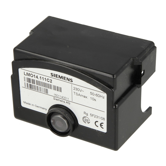
- Page 4 Mechanical design The housing is made of impact-proof, heat-resistant and flame-retarding plastic. It is of plug-in design and engages audibly in the base. Burner controls LMO... are designed in black plastic. The housing accommodates the microcontroller for the control sequence and the print relays for load control electronic flame signal amplifier lockout reset button with its integrated multicolor signal lamp (LED) for operational status and fault status messages and the socket for connecting the OCI400...
- Page 5 Ordering Oil burner control (without plug-in base) refer to «Type summary» Connection accessories for small burner controls refer to Data Sheet N7201 Plug-in base AGK11... Cable holders AGK65..., AGK66 Flame detectors Photo resistive detectors QRB1... refer to Data Sheet N7714 Blue-flame detectors QRC1...
- Page 6 Technical data General unit data Mains voltage AC 230 V +10 % / -15 % AC 120 V +10 % / -15 % Mains frequency 50...60 Hz ±6 % External primary fuse (Si) 6.3 A (slow) Power consumption 12 VA Perm.
- Page 7 Technical data (cont´d) Flame supervision with Detector current Perm. detector Possible detector current QRB... or QRC... required current with flame (with flame) (without flame) (typically) QRB... ¹) Min. 45 µA Max. 5.5 µA 100 µA QRC... ¹) Min. 45 µA Max.
- Page 8 Function Preconditions for Burner control is reset startup Reset button not used «EK1» «EK2» All contacts in the line are closed and there is demand for heat No undervoltage Flame detector is darkened and there is no extraneous light Undervoltage Safety shutdown from the operating position takes place should mains voltage drop below about AC 165 V (U = AC 230 V) or AC 75 V (U...
- Page 9 Operation, display, diagnostics Operation Lockout reset button «EK» is the key operating element for resetting the burner control and for activating / deactivating the diagnostic functions. The multicolor signal lamp (LED) in the lockout reset button is the key Yellow indicating element for both visual diagnostics and interface diagnostics.
- Page 10 Operation, display, diagnostics (cont´d) After lockout, the red signal lamp (LED) remains steady on. In that condition, the visual Diagnostics of the cause of fault diagnostics of the cause of fault according to the error code table can be activated by pressing the lockout reset button for more than 3 seconds.
- Page 11 Connection diagram and internal diagram LMO14... Control sequence LMO14... A´ µC control µC2 µC1 Only with LMO14.113C2: re-ignition 7130a01e/0700 7130d02e/1207 Connection diagram and internal diagram LMO24... Control sequence LMO24... A´ µC control µC2 µC1 t1´ Only with LMO24.113C2: re-ignition 7130a04e/0908 7130d03e/1207 Connection diagram and internal diagram LMO44…...
- Page 12 Legend Alarm device BV... Fuel valve Lockout reset button Remote lockout reset button Flame signal Flame signal amplifier K... Contacts of control relay Cable link (required only when no oil preheater is used) 3-color signal lamp Burner motor Release contact of oil preheater Oil preheater QRB...
- Page 13 Type reference Length «L» in mm AGK20.19 AGK20.43 AGK20.55 Distribuitor: FLAME POWER SRL 021-3121727 ; 0744-340566 contact@arzatoare.ro ; www.arzatoare.ro 2013 Siemens AG Infrastructure & Cities Sector Building Technologies Subject to change! 13/13 Building Technologies Division CC1N7130en Infrastructure & Cities Sector...