
Related Manuals for Mitsubishi Electric CC-Link IE-NZ2GNSS2-8D


Summary of Contents for Mitsubishi Electric CC-Link IE-NZ2GNSS2-8D
- Page 1 CC-Link IE TSN Remote I/O Module (With Safety Functions) User's Manual -NZ2GNSS2-8D -NZ2GNSS2-8TE -NZ2GNSS2-16DTE 'TRANSLATION OF THE ORIGINAL INSTRUCTIONS'...
-
Page 3: Safety Precautions
SAFETY PRECAUTIONS (Read these precautions before using this product.) Before using this product, please read this manual and the relevant manuals carefully and pay full attention to safety to handle the product correctly. The precautions given in this manual are concerned with this product only. For the safety precautions of the programmable controller system, refer to the user's manual for the CPU module used. - Page 4 [Design Precautions] WARNING ● When the safety remote I/O module detects an error in an external power supply or a failure in the module, it turns off the outputs. Configure an external circuit to ensure that the power source of a hazard is shut off by turning off the outputs.
- Page 5 [Security Precautions] WARNING ● To maintain the security (confidentiality, integrity, and availability) of the programmable controller and the system against unauthorized access, denial-of-service (DoS) attacks, computer viruses, and other cyberattacks from external devices via the network, take appropriate measures such as firewalls, virtual private networks (VPNs), and antivirus solutions.
- Page 6 [Wiring Precautions] CAUTION ● Individually ground the FG terminal of the programmable controller with a ground resistance of 100 ohms or less. Failure to do so may result in electric shock or malfunction. ● Check the rated voltage and terminal layout before wiring to the module, and connect the cables correctly.
- Page 7 [Startup and Maintenance Precautions] WARNING ● Do not touch any terminal while power is on. Doing so will cause electric shock or malfunction. ● Shut off the external power supply (all phases) used in the system before cleaning the module or retightening the terminal block mounting screw.
- Page 8 [Disposal Precautions] CAUTION ● When disposing of this product, treat it as industrial waste. [Precautions for Using Products] WARNING ● Although MELCO has obtained the certification for Product's compliance to the international safety standards IEC 61508 and ISO 13849-1 from TUV Rheinland, this fact does not guarantee that Product will be free from any malfunction or failure.
-
Page 9: Conditions Of Use For The Product
CONDITIONS OF USE FOR THE PRODUCT (1) Although MELCO has obtained the certification for Product's compliance to the international safety standards IEC61508, ISO13849-1 from TUV Rheinland, this fact does not guarantee that Product will be free from any malfunction or failure. The user of this Product shall comply with any and all applicable safety standard, regulation or law and take appropriate safety measures for the system in which the Product is installed or used and shall take the second or third safety measures other than the Product. -
Page 10: Introduction
INTRODUCTION Thank you for purchasing the CC-Link IE TSN remote I/O module (with safety functions) (hereinafter referred to as safety remote I/O module). This manual describes the procedures, system configuration, parameter settings, functions, and troubleshooting of the relevant products listed below. Before using this product, please read this manual and the relevant manuals carefully and develop familiarity with the functions and performance of the safety remote I/O module to handle the product correctly. -
Page 11: Table Of Contents
CONTENTS SAFETY PRECAUTIONS ..............1 CONDITIONS OF USE FOR THE PRODUCT . - Page 12 Safety Communication Setting ............65 CHAPTER 8 FUNCTIONS Safety Input .
- Page 13 Details of remote registers..............135 Appendix 4 Remote Buffer Memory .
-
Page 14: Relevant Manuals
System configuration, parameter settings, and online operations of GX e-Manual [SH-081215ENG] Works3 e-Manual refers to the Mitsubishi Electric FA electronic book manuals that can be browsed using a dedicated tool. e-Manual has the following features: • Required information can be cross-searched in multiple manuals. -
Page 15: Terms
TERMS Unless otherwise specified, this manual uses the following terms. Term Description Authentication Class A group of devices and switching hubs compatible with CC-Link IE TSN, ranked according to the functions and performance by the CC-Link Partner Association. For Authentication Class, refer to the CC-Link IE TSN Installation Manual (BAP-C3007ENG-001) published by the CC- Link Partner Association. -
Page 16: Chapter 1 Product Lineup
PRODUCT LINEUP List of Products Input modules Module name Input specifications Module power Weight Model Reference supply current DC input module Negative Spring clamp terminal block 160mA 0.25kg NZ2GNSS2-8D Page 19 common type 24VDC, 8 points NZ2GNSS2-8D DC input module Output modules Module name Output specifications... - Page 17 MEMO 1 PRODUCT LINEUP 1.1 List of Products...
-
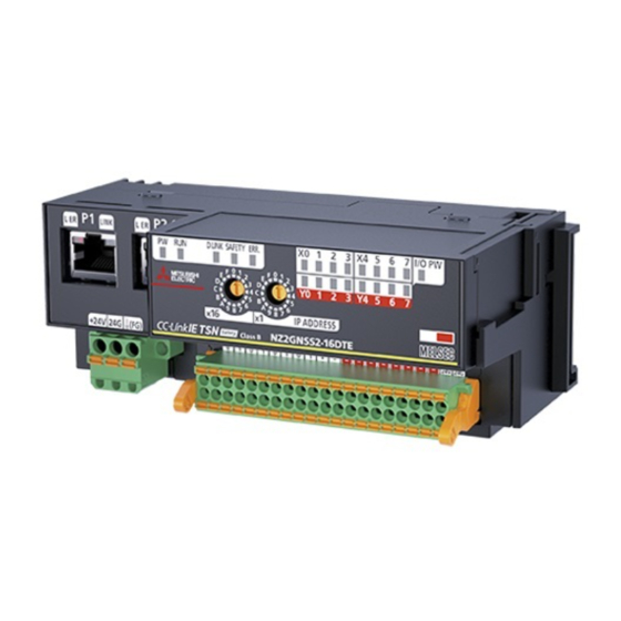
Page 18: Chapter 2 Part Names
PART NAMES The part names of the safety remote I/O module are listed below. Name Description A port for the connection to CC-Link IE TSN (RJ45 connector) Connect an Ethernet cable. (Page 47 Wiring of Ethernet Cable) There are no restrictions on the connection order of the cables for P1 and P2. L ER LED Indicates the port status. - Page 19 Name Description DIN rail hook A hook to mount a safety remote I/O module on a DIN rail. I/O terminal block A terminal block for I/O power supply and I/O signals *1 When cyclic transmission is stopped only for the master station, the safety remote I/O module maintains the cyclic transmission. Thus, the D LINK LED turns on.
-
Page 20: Chapter 3 Specifications
SPECIFICATIONS This chapter describes the specifications of the safety remote I/O module. General Specifications Item Specifications Operating ambient temperature 0 to 55 Storage ambient temperature -40 to 75 Operating ambient humidity 5 to 95%RH, non-condensing Storage ambient humidity Vibration resistance Compliant with JIS Frequency Constant... -
Page 21: Performance Specifications
Performance Specifications Input module NZ2GNSS2-8D DC input module Item NZ2GNSS2-8D Station type Remote station Authentication Class Authentication Class B Network topology Line topology, star topology, mixture of star topology and line topology, ring topology Number of input points Single wiring: 8 points, double wiring: 4 points Rated input voltage 24VDC (ripple ratio: 5% or less) (allowable voltage range: 20.4 to 28.8VDC) Rated input current... - Page 22 Item NZ2GNSS2-8D Weight 0.25kg *1 The performance specifications vary depending on firmware versions of modules used. ( Page 159 Added and Changed Functions) *2 To connect to the safety remote I/O module, use the power supply that meets the following conditions: ...
- Page 23 ■I/O terminal block 17 18 19 20 38 39 40 Terminal number Signal name Terminal number Signal name COM+ COM+ COM- COM- COM- COM- COM- COM- COM- COM- COM- COM- IO24V IO24V IO24G IO24G Among the terminals with the same signal name, you can choose any terminals since they are internally connected. In addition, NC is reserved.
-
Page 24: Output Module
Output module NZ2GNSS2-8TE transistor output module Item NZ2GNSS2-8TE Station type Remote station Authentication Class Authentication Class B Network topology Line topology, star topology, mixture of star topology and line topology, ring topology Number of output points Single wiring: 8 points, double wiring: 4 points Rated load voltage 24VDC (ripple ratio: 5% or less) (allowable voltage range: 20.4 to 28.8VDC) Maximum load current... - Page 25 Item NZ2GNSS2-8TE Weight 0.25kg *1 The performance specifications vary depending on firmware versions of modules used. ( Page 159 Added and Changed Functions) *2 To connect to the safety remote I/O module, use the power supply that meets the following conditions: ...
- Page 26 ■I/O terminal block 17 18 19 20 38 39 40 Terminal number Signal name Terminal number Signal name COM+ COM+ COM- COM- COM- COM- COM- COM- COM- COM- COM- COM- IO24V IO24V IO24G IO24G Among the terminals with the same signal name, you can choose any terminals since they are internally connected. In addition, NC is reserved.
-
Page 27: I/O Combined Module
I/O combined module NZ2GNSS2-16DTE DC input/transistor output module Item NZ2GNSS2-16DTE Station type Remote station Authentication Class Authentication Class B Network topology Line topology, star topology, mixture of star topology and line topology, ring topology Number of input points Single wiring: 8 points, double wiring: 4 points Rated input voltage 24VDC (ripple ratio: 5% or less) (allowable voltage range: 20.4 to 28.8VDC) Rated input current... - Page 28 Item NZ2GNSS2-16DTE Page 44 Applicable solderless terminal Applicable solderless Terminal block for module terminal power supply and FG Page 49 Applicable solderless terminal I/O terminal block Multicast filter Available Cyclic transmission RX/RY points 16 points RWr/RWw points 4 points SA\X / SA\Y points SA\X: 32 points, SA\Y: 16 points *2*4 Module power supply...
- Page 29 ■External wiring Terminal block for module power supply and FG Pin No. Signal name 24VDC Fuse +24V +24V I/O terminal block Reverse +24V IO24V connection protection circuit 24VDC IO24V IO24G IO24G Safety switch A device such as safety sensor 24VDC Control 24V IN output 1...
- Page 30 ■I/O terminal block 17 18 19 20 38 39 40 Terminal number Signal name Terminal number Signal name COM+ COM+ COM- COM- COM- COM- COM- COM- COM- COM- COM- COM- IO24V IO24V IO24G IO24G Among the terminals with the same signal name, you can choose any terminals since they are internally connected. In addition, NC is reserved.
-
Page 31: Safety Remote I/O Module Safety Response Time
The safety response time of the safety remote I/O module is shown below. For the response time including the transmission delay time, refer to the following. Mitsubishi Electric Safety Programmable Controller MELSEC iQ-R Series Machinery Directive (2006/42/EC) Compliance Input Transmission interval monitoring time ... -
Page 32: Function List
Function List The following table lists the functions of the safety remote I/O module. : Available, : Not available Item Description Function availability Reference Input Output module module combined module Safety input Safety input wiring The safety double wiring function or safety Page 70 Safety selection function single wiring function can be selected for input... - Page 33 Operation mode and state transition The following describes the state transition and transition conditions of the safety remote I/O module. (1) Power supply OFF state (2) Initial processing state (3) Unit test mode (6) Moderate error status (4) Standby mode (7) Major error status (5) Safety drive mode *1 When a moderate error or major error has occurred, the state is changed into an error state.
-
Page 34: Chapter 4 Procedures Before Operation
PROCEDURES BEFORE OPERATION This chapter describes the procedures before operation. Consideration of system configuration Determine a safety category required for configuring the safety system. Determine function wiring required for configuring the safety system. Safety remote I/O module installation, wiring, and parameter setting IP address setting switch setting Set the fourth octet of IP address of the safety remote I/O module. - Page 35 MEMO 4 PROCEDURES BEFORE OPERATION...
-
Page 36: Chapter 5 System Configuration
SYSTEM CONFIGURATION This chapter describes the safety system configuration using a safety remote I/O module. For details on the CC-Link IE TSN configuration, refer to the following. User's manual for the master station used Applicable Systems Applicable products When using a safety remote I/O module, use the following products. For model names of the Safety CPU and the safety function module, refer to the following. - Page 37 Applicable profile A profile is required to use the safety remote I/O module in the CC-Link IE TSN configuration setting. When the latest profile of the safety remote I/O module is necessary, please consult your local Mitsubishi representative. The profile is a setting file that stores information required for the start-up, operation, and maintenance of devices supporting the CC-Link family.
-
Page 38: Safety Standards
Safety Standards Observe the following safety standards. Region Standard Global IEC 61508 (SIL3), IEC 62061 (SIL3), ISO 13849-1 (Category 4 PL.e) IEC 61131-2 IEC 61000-6-2, IEC 61000-6-4 IEC 61784-3 IEC 60204-1 Europe EN ISO 13849-1 (Category 4 PL.e) EN 61131-2 EN 61000-6-2, EN 61000-6-4 North America UL 61010-1, UL 61010-2-201... -
Page 39: Chapter 6 Installation And Wiring
INSTALLATION AND WIRING This chapter describes the installation and wiring of the safety remote I/O module. IP Address Setting Switch Setting Set the fourth octet of IP address using the IP address setting switch on the front of the safety remote I/O module. The setting of the IP address setting switch is enabled when the safety remote I/O module is powered on. - Page 40 Setting range The setting value must be in the range between 1 and 254. When a value in the range between 1 and 254 is set, the IP address and subnet mask are as follows. • The first three octets of the IP address: Octets one, two, and three from the IP address of the master station are used for operation.
-
Page 41: Installation Environment And Installation Position
Installation Environment and Installation Position Installation environment Installation location Do not install the safety remote I/O module in a location where: • Ambient temperature is outside the range of 0 to 55; • Ambient humidity is outside the range from 5 to 95% RH; •... -
Page 42: Installation Direction
Installation direction The safety remote I/O module can be installed in six directions. Use the DIN rail (1) to install the safety remote I/O module. 6 INSTALLATION AND WIRING 6.2 Installation Environment and Installation Position... -
Page 43: Installation
Installation Mounting the modules on a DIN rail The following procedure is just an example of fixing the module with a DIN rail stopper. When fixing the safety remote I/O module, refer to the manual of the DIN rail stopper used. Installation procedure Pull down the DIN rail hooks on the back of the safety remote I/O module. - Page 44 Hitch the upper hook of the DIN rail stopper to the top of Hitch the hook to the DIN rail. top of the DIN rail Slide the DIN rail stopper up to the left side of the safety DIN rail remote I/O module.
- Page 45 Removal procedure Remove the safety remote I/O module from the DIN rail by reversing the installation procedure. Applicable DIN rail models Use the following DIN rails that are compliant with JIS C 2812 and IEC 60715. • TH35-7.5Fe • TH35-7.5Al Interval between DIN rail mounting screws Tighten the screws at intervals of 200mm or less.
-
Page 46: Wiring Of Terminal Block For Module Power Supply And Fg
Wiring of Terminal Block for Module Power Supply and FG Tightening torque Tighten the terminal block mounting screws within the following specified torque range. Tightening the screws too much may damage the safety remote I/O module case. Screw type Tightening torque range Terminal block mounting screw (M2.5 screw) 0.2 to 0.3Nm Wire to be used... - Page 47 Connecting and disconnecting the cable To connect the cable, fully insert a wire with a bar solderless terminal into a wire insertion opening. After inserting the wire, pull it lightly to check that it is securely clamped. To disconnect the cable, push in the open/close button with a flathead screwdriver. With the button pushed in, pull out the wire having a bar solderless terminal.
- Page 48 Precautions • Use a bar solderless terminal for the wiring to the push-in type spring clamp terminal block. If a stripped wire is inserted into a wire insertion opening, the wire cannot be securely clamped. • For how long the wire should be stripped, follow the specifications of the bar solderless terminal used. To attach a bar solderless terminal to a wire, use a crimping tool.
-
Page 49: Wiring Of Ethernet Cable
Wiring of Ethernet Cable Wiring method ■Installation method Power off the module power supply of the safety remote I/O module and the power supply of the external device. Push the Ethernet cable connector into the safety remote I/O module until it clicks. Pay attention to the connector's direction. - Page 50 Precautions ■Laying Ethernet cables • Place the Ethernet cable in a duct or clamp it. If not, dangling cable may swing or inadvertently be pulled, resulting in damage to the safety remote I/O modules or cables or malfunction due to poor contact. •...
-
Page 51: Wiring Of External Device And I/O Terminal Block
Wiring of External Device and I/O Terminal Block Wire to be used The following table shows the type of wire to be used for connection to the I/O terminal block and the external devices. Diameter Type Material Temperature rating 20 to 16 AWG Stranded wire Copper wire 75... - Page 52 Installing or removing the terminal block The following procedures show how to install and remove the terminal block. ■Lock and release lever positions To make it easy to install and remove the terminal block, a three-stage positioning stopper is attached so that the lever does not freely turn around.
- Page 53 Connecting and disconnecting the cable ■Connecting the cable Insert a wire with a bar solderless terminal into the wire insertion opening (2) and push it all the way in. If the wire cannot be inserted by this method, insert the wire all the way in while pressing the open/close button (1) using a flathead screwdriver with a tip width of 2.0 to 2.5mm.
- Page 54 Processing method of the cable terminal Strip the cable about 10mm from the tip to connect a bar solderless terminal at the stripped area. Stripping the cable too long may cause electric shock or short circuit between adjacent terminals because the conductive part sticks out of the terminal block.
-
Page 55: Precautions For Wiring The Safety Remote I/O Module To Safety Devices
Precautions for wiring the safety remote I/O module to safety devices When wiring the input part ■Combination of input terminals for double input For double input, the input terminals can be used only in the combinations shown below. Combination of input terminals for double input X0, X1 X2, X3 X4, X5... -
Page 56: Chapter 7 Settings
SETTINGS Network Configuration Settings Set the parameters of the safety remote I/O module with the network parameters written to the CPU module of the master station. For the setting procedure for the master station, refer to the following. User's manual for the master station used Communication cycle interval setting When using the safety remote I/O module, set values listed in the tables below for "Communication Period Interval Setting"... - Page 57 Window Network topology setting When using the safety remote I/O module, set the network topology setting as follows. Firmware version of safety remote I/O module Setting item "02" or later • Line topology, star topology, or mixture of star topology and line topology •...
- Page 58 Setting item list Item Setting details Setting range RX Setting, RY Setting Points Set the assignment of RX/RY points. 0 to 16 (Default value: 16) Start The RX/RY start number is displayed. The RX/RY end number is displayed. RWr Setting, RWw Setting Points Set the assignment of RWr/RWw points.
-
Page 59: Parameter Setting
Parameter Setting Parameter setting of the safety remote I/O module can be done with the following methods. • Slave station parameter automatic setting (Page 59 Slave station parameter automatic setting) • Parameter processing of slave station (Page 62 Parameter processing of slave station) Even if the safety remote I/O module is replaced due to a failure of the safety remote I/O module when parameters are set with slave station parameter automatic setting, the parameters of the safety remote I/O module are automatically set via the master station. - Page 60 Item Setting details Setting range Reference Basic module Double input discrepancy auto recovery When double input discrepancy 0: Not used Page 145 Double input parameter setting occurs, set whether to keep the 1: Used discrepancy auto abnormal point in the stop state, recovery setting or to automatically return when the error is resolved.
-
Page 61: Slave Station Parameter Automatic Setting
Slave station parameter automatic setting Slave station parameter automatic setting writes the parameters of the safety remote I/O module to the CPU module. The parameters of the safety remote I/O module are saved in the CPU internal memory. When the safety remote I/O module enters or returns to the network, the parameters of the safety remote I/O module are automatically set via the master station. - Page 62 Right-click the safety remote I/O module and select "Parameter of Slave Station" to display the "Parameter of Slave Station" window. Set each parameter on the "Parameter of Slave Station" window. For "Safety authentication code", set a value that does not overlap with those of other safety remote I/O modules, such as a MAC address.
- Page 63 Select [Close with Reflecting the Setting] and close the "Parameter of Slave Station" window. Select [Close with Reflecting the Setting] and close the "CC-Link IE TSN Configuration" window. Display the refresh parameter setting window and configure the setting as follows. [Navigation window] ...
-
Page 64: Parameter Processing Of Slave Station
Parameter processing of slave station The following describes the procedure for setting module parameters of the safety remote I/O module from the "Network Configuration Settings" window. Parameter setting Operating procedure Open the "CC-Link IE TSN Configuration" window. [Navigation window] [Parameter] [Module Information] Model [Basic Settings] [Network Configuration Settings] Select the safety remote I/O module in "Module List"... - Page 65 Set "Method selection" to "Parameter write" so that setting values can be set in the items of "Write Value/Setting Value". Set values in all the items of "Write Value/Setting Value". If an item where a value is not set exists, "Parameter write" cannot be executed.
- Page 66 After "Parameter write" is complete, the following window is displayed. Select [Close with Reflecting the Setting] and close the "Parameter of Slave Station" window. Select [Close with Reflecting the Setting] and close the "CC-Link IE TSN Configuration" window. Display the refresh parameter setting window and configure the setting as follows. [Navigation window] ...
-
Page 67: Safety Communication Setting
Safety Communication Setting Write the safety communication setting of the master station to the CPU module. Make the following settings before configuring the safety communication setting. Check that the safety remote I/O module and master/local module can perform cyclic transmission (the D LINK LED is lit). Page 54 Network Configuration Settings Page 57 Parameter Setting Operating procedure... - Page 68 Select "Local Network" in "Communication Destination", and the "Select the target module for the Safety Communication Setting" window is displayed. Select the target safety remote I/O module and click the [Add] button. The parameters of the safety remote I/O module selected on the "Select the target module for the Safety Communication Setting"...
- Page 69 After applying the module parameter setting of the master station, perform "Write to PLC". For the module parameter setting of the master station, refer to the following. User's manual for the master station used When "Write to PLC" is completed, right-click the target safety remote I/O module in the "Network Configuration Settings" and display the "Command Execution of Slave Station"...
- Page 70 Clicking the [Execute] button displays a confirmation window. Check the contents and click the [Yes] button. The SAFETY LED of the selected safety remote I/O module starts flashing. Visually check that the safety remote I/O module on which the SAFETY LED is flashing is installed on the desired position. At the same time, visually check that the SAFETY LEDs of other safety remote I/O modules not targeted for the position checking are not flashing.
- Page 71 Select "Safety module validation" in "Method selection" and click the [Execute] button. Clicking the [Execute] button displays the following confirmation window. Check the contents, and if the operations mentioned on the window are completed, click the [Yes] button. When the operations are not completed, click the [No] button.
-
Page 72: Chapter 8 Functions
FUNCTIONS This chapter describes the functions available in the safety remote I/O module, and the setting procedures for those functions. For details on safety remote I/O signals, remote control/monitor signals, and remote buffer memory, refer to the following. Page 127 Safety Remote I/O Signals Page 133 Remote Control/Monitor Signals Page 138 Remote Buffer Memory Safety Input... - Page 73 Safety single wiring function This function can connect input devices with single wiring. (1) Safety remote I/O module Use the safety double wiring function to comply with SIL3 or Category 4 PL.e. Systems using safety single wiring do not comply with SIL3 or Category 4 PL.e, although the wiring is used for input using safety devices.
- Page 74 ■States of safety remote inputs (SA\X0, SA\X1) for X0 and X1 (double wiring) Double input discrepancy detection state Input terminal status: X0 Input terminal status: X1 SA\X0 SA\X1 (1) Even when the input terminal X0 turns on, SA\X0 does not turn on because X1 is off. (2) When the double inputs are on (X0 and X1 are on), safety remote inputs (SA\X0 and SA\X1) turn on.
-
Page 75: Standard Input
Standard Input This function inputs external signals. This function cannot be used in any modes other than the safety drive mode. All the safety remote inputs (SA\X) are off in any modes other than the safety drive mode. Unlike the safety input function, this function cannot use the input diagnostic function. Standard input wiring selection function Sets the standard single wiring function for input wiring. -
Page 76: Input Response Time Setting Function
Input Response Time Setting Function This function is used to set the filter time to reduce incorrect inputs caused by noise in input signals. The longer the input response time is, the higher tolerance for chattering and noise the module has. But the response to input signals becomes slower. -
Page 77: Safety Output
Safety Output This function safely outputs signals. This function cannot be used in any modes other than the safety drive mode. All the safety remote outputs (SA\Y) are off in any modes other than the safety drive mode. Safety output wiring selection function The safety double wiring function or safety single wiring function can be selected for output wiring. - Page 78 Diagnostic functions to detect output errors Output errors can be detected by using the following diagnostic functions. Diagnostic function Description Reference Page 95 Output dark test Output dark test function Outputs test pulses to turn off the outputs that are on and diagnoses contacts for failure.
- Page 79 Setting method Set the safety output wiring selection in "Wiring selection of output" from the "Parameter of Slave Station" window of the engineering tool. Set safety output to either "1: Safety double wiring (Source/Source)" or "2: Safety single". Item Setting range Wiring selection of output Yn 0: Not used 1: Safety double wiring (Source/Source)
-
Page 80: Fast Logic Function
Fast logic function Output control according to the input status is performed inside the safety remote I/O module without going through the master station. Because the output status can be changed without CPU module processing such as programs, high-speed output control is possible. The fast logic function can only be used with an I/O combined module. - Page 81 Logic patterns of fast logic function The logic patterns of the fast logic function can be selected from the following four patterns. Fast logic pattern setting Logical operation circuit of fast logic Pattern 1 Four safety double wiring inputs (without X0/X1 reset signal) X2/X3...
- Page 82 Fast logic interlock When the output is turned off by the fast logic function, the output is interlocked. When the fast logic interlock state is entered, the output signals (Y0/Y1) do not turn ON again unless there is a restart instruction, reset signal, or start signal input from the CPU module.
- Page 83 Operation at fast logic start The fast logic function operates in the safe operation mode, and operation is stopped (output OFF) except in the fast logic interlock state and the safe operation mode. The operation when the fast logic pattern setting is Pattern 2 is shown below. Operating procedure Turn off and on the safety output enable signals (SA\Y0, SA\Y1).
- Page 84 • The fast logic function turns off the output signals (Y0, Y1) and stops operation when the safety remote I/O module enters major or moderate error status. • If the input point is turned off due to a minor error, remove the cause of the error and then operate the fast logic initial request flag (SA\Y8) and fast logic start flag (SA\Y9) to start operation of the fast logic function.
- Page 85 Operation when fast logic output is off ■When fast logic interlock is enabled When all the corresponding output signal points are turned off by the fast logic function, the fast logic READY (SA\XC) is turned off, the fast logic function stops operating, and the fast logic interlock state is entered. When restarting the fast logic function, turning off and on the fast logic initial request flag (SA\Y8) and fast logic start flag (SA\Y9), or operating the reset signal X7 and start signal X6 causes fast logic READY (SA\XC) to turn ON and the operation to resume.
- Page 86 ■When fast logic interlock is disabled Even when the output is turned off by the fast logic function, fast logic READY (SA\XC) remains on and the fast logic function does not stop. Operations of the fast logic initial request flag (SA\Y8) and fast logic start flag (SA\Y9), or operations of the reset signal X7 and start signal X6 will be ignored.
- Page 87 Operation when safety output enable signal is off ■When fast logic interlock is enabled When the safety output enable signals (SA\Y0, SA\Y1) are turned off while the output signals (Y0, Y1) are on, all output signal points are turned off, fast logic READY (SA\XC) turns off, the fast logic function stops operating, and the fast logic interlock state is entered.
- Page 88 ■When fast logic interlock is disabled Turning off the safety output enable signals (SA\Y0, SA\Y1) turns off all the output signal points. Since fast logic interlock is disabled, output resumes when the safety output enable signals (SA\Y0, SA\Y1) are turned on. The operation when the fast logic pattern setting is Pattern 2 is shown below.
- Page 89 Fast logic function parameter setting method ■Fast logic pattern setting Enable/disable the fast logic function and set the logic pattern. Fast logic pattern setting is done with "Fast logic pattern setting" from the "Parameter of Slave Station" window of the engineering tool.
- Page 90 Fast logic pattern setting Wiring selection of input/output Setting value Pattern 3 Wiring selection of input Safety double wiring (NC/NC) Three safety double wiring inputs (with reset signal) Safety double wiring (NC/NC) Safety double wiring (NC/NC) Safety single Safety single Wiring selection of output Safety double wiring (Source/Source) Not used...
-
Page 91: Input Diagnostic
Input Diagnostic The input diagnosis function is a safety function for determining failure of input signals using the safety input function. Double input discrepancy detection function Discriminates failures by monitoring the discrepancy state of doubled safety remote inputs (SA\X). Double input discrepancy detection If "Double input discrepancy detection setting"... - Page 92 ■Operation at error detection When the discrepancy state of double inputs continues for the set time or longer, the double input discrepancy detection error (error code: 0203H) state is applied to the safety remote I/O module, and the corresponding input point is turned off. For the error state, refer to the following.
- Page 93 Double input discrepancy detection time When the double input discrepancy detection time is set, an error does not occur during the set detection time even if double input discrepancy occurs. The following table lists the relation of each double input evaluation result and the double input discrepancy detection time.
- Page 94 Double input discrepancy auto recovery function When a double input discrepancy detection error has occurred, removing the error factor recovers the module into the normal state automatically. By enabling this function, the reset operation of the safety remote I/O module to reset errors is not required. When this function is enabled and a double input discrepancy is detected, the minor error state is applied to the safety remote I/O module.
-
Page 95: Input Dark Test Function
Input dark test function Outputs test pulses to turn off the external input signals (X0 to X7) that are on and diagnoses contacts including external devices for failure. Failures including circuit fixing and short-circuit faults can be detected. The input dark test detects a short-circuit fault that occurs between Xn (n: even number) and Xn+1. The Xn is an input terminal to be connected to T0, and the Xn+1 is an input terminal to be connected to T1. - Page 96 Setting method Set the following parameters for the input dark test function. There is a mutual relation of the parameter values of the input response time and input dark test. When setting parameters, set values that meet the mutual relation. For details, refer to the following. Page 74 Relation of the parameters for the input response time and input dark test ■Input dark test execution setting Set whether to perform the input dark test or not in "Input dark test execution setting"...
-
Page 97: Output Diagnostic
Output Diagnostic The output diagnosis function is a safety function for determining failure of output signals using the safety output function. Output dark test function Outputs test pulses to turn off the external output signals (Y0 to Y7) that are on and diagnoses the internal circuit for failure. The read-back circuit checks the test pulse and output circuit fixing can be detected. - Page 98 Setting method Set the following parameters for the output dark test function. ■Output dark test execution setting Set whether to perform the output dark test in "Output dark test execution setting" from the "Parameter of Slave Station" window of the engineering tool. Item Setting range Output dark test execution setting Y0 to Y7...
-
Page 99: Output Read-Back Function
Output read-back function Reads back output results and diagnoses whether the external output signals (Y0 to Y7) are correctly output. By diagnosing whether the output terminal status matches the output data of the safety device, the output read-back function detects output operation errors of the safety remote I/O module. To use this function, setting parameters is not required. -
Page 100: Protection Functions
Protection Functions Prevents effects due to overvoltage and overcurrent from spreading to other modules of the safety system. The following table lists the protection functions. Function name Purpose Description Module power supply Prevents ignition or burnouts from/of the safety remote I/O This function operates when the module power supply is in the overvoltage protection module due to overvoltage on the primary side. -
Page 101: User Authentication Function
User Authentication Function Limits the users (persons and personal computers) that can access the CPU module or safety remote I/O module. Using this function permits only the specified users to access the CPU module. This function is implemented in the CPU module used. For details on the user authentication function, refer to the following. ... -
Page 102: Communication Speed Setting Function
Communication Speed Setting Function This function sets the communication speed. Setting method The communication speed can be set with the parameter. For details, refer to the following. Page 144 Communication speed setting Operating status A communication speed at which the safety remote I/O module is operating can be checked with the remote register. For details, refer to the following. -
Page 103: Chapter 9 Maintenance And Inspection
MAINTENANCE AND INSPECTION This chapter describes the maintenance and inspection of the safety remote I/O module. Read [Startup and Maintenance Precautions] in the safety precautions carefully before performing the inspection, and observe the precautions. Daily Inspection The following table lists the items that must be inspected on a daily basis. Item Inspection item Inspection method... -
Page 104: Periodic Inspection
Periodic Inspection This section describes items that must be inspected one or two times every six months to one year. When the equipment has been relocated or modified, or cable laying has been changed, inspect the module for the items. Item Inspection item Inspection method... -
Page 105: Chapter 10 Troubleshooting
TROUBLESHOOTING This chapter describes the errors that may occur while the safety remote I/O module is used and their troubleshooting. 10.1 CC-Link IE TSN/CC-Link IE Field Diagnostics For CC-Link IE TSN, monitor the status and conduct an operation test. For details on CC-Link IE TSN/CC-Link IE Field diagnostics, refer to the following. ... - Page 106 Checking station information Information on safety remote I/O modules where data link is established are displayed in the "Station Information List" window. Information on each safety remote I/O module, such as the production information and firmware version, can be checked by clicking the [Station Information List] button in the "CC-Link IE TSN/CC-Link IE Field Diagnostics"...
-
Page 107: Checking The Leds
10.2 Checking the LEDs This section describes how to troubleshoot the system by the LEDs. When the PW LED does not turn on When the PW LED does not turn on, check the following items. Check item Action Is any LED other than the PW LED on? When any LED other than the PW LED is on, the possible cause is a hardware failure. - Page 108 When the D LINK LED turns off When the D LINK LED turns off, check the following items. Check item Action Is the safety remote I/O module on the network operating normally? Connect the engineering tool to the master station, and check that the safety remote I/ O module is data-linked using the CC-Link IE TSN/CC-Link IE Field diagnostics.
- Page 109 When the D LINK LED flashes When the D LINK LED flashes, check the following items. Check item Action Does the IP address setting of the safety remote I/O module match Match the IP address of the safety remote I/O module with the IP address specified in the IP address of the safety remote I/O module specified in the the network configuration settings of the master station or the CC-Link IE TSN network configuration settings of the master station?
- Page 110 When the SAFETY LED turns off When the SAFETY LED turns off, check the following items. Check item Action Have parameters been set to the safety remote I/O module? Set parameters to the safety remote I/O module. ( Page 57 Parameter Setting) If the parameters are changed, configure the safety communication setting and safety module validation again.
- Page 111 When the LINK LED turns off When the LINK LED turns off, check the following items. Check item Action Are Ethernet cables used compliant with the relevant standard? Replace the cable with an Ethernet cable compliant with the relevant standard. ...
-
Page 112: Unit Test
10.3 Unit Test Run a unit test to check if there is any hardware failure in the safety remote I/O module. Power off the power supply of the safety remote I/O module. Connect P1 and P2 of the safety remote I/O module with an Ethernet cable. Set the IP address setting switch as follows. -
Page 113: Troubleshooting By Symptom
10.4 Troubleshooting by Symptom Perform the troubleshooting by symptom when the safety remote I/O module does not operate properly with no error. If an error occurs in the safety remote I/O module, identify the cause of the error using the engineering tool. When the ON/OFF status of a safety input cannot be read When the ON/OFF status of a safety input cannot be read, check the following items. - Page 114 When safety output cannot be turned on When a safety output cannot be turned on, check the following items. Check item Action Is the SAFETY LED on? When the SAFETY LED is not on, "Safety module validation" has not been performed or the CPU module is in the safety station interlock status.
-
Page 115: Fault Examples With The Safety Remote I/O Module
10.5 Fault Examples with the Safety Remote I/O Module Troubleshooting for input circuit This section describes the troubleshooting for input circuit. An input signal does not turn off. ■Cause Drive by a switch with LED indicator DC input Input Leakage current module ■Action Connect an appropriate resistor as shown below so that a current through the input module may become lower than the OFF... - Page 116 The OFF current of NZ2GNSS2-8D is not 1.3mA or lower. Therefore, connect a resistor as shown below. Input resistance 2.6kΩ = 1.3mA 3.0mA = 3.7V = 1.7mA COM- To satisfy the condition that the OFF current of NZ2GNSS2-8D is 1.3mA or lower, the current through the connected resistor should be 1.7mA or higher.
-
Page 117: Troubleshooting For Output Circuit
Troubleshooting for output circuit This section describes the troubleshooting for output circuit. A load momentarily turns on from off when the system is powered off ■Cause When an inductive load is connected, the load [2] in the off state may turn on due to a sneak current from the back EMF at the shutoff [1]. -
Page 118: Method For Checking Error Codes
10.6 Method for Checking Error Codes Error codes can be checked by any of the following methods: • Checking with the engineering tool • Checking by Error code (RWr1) Checking with the engineering tool The error history held in the safety remote I/O module can be read. Errors that occurred before powering-off can be checked as well. - Page 119 ■Checking by using CC-Link IE TSN/CC-Link IE Field diagnostics Operating procedure Connect the engineering tool to the CPU module. Start "CC-Link IE TSN/CC-Link IE Field Diagnostics" from the menu. [Diagnostics] [CC-Link IE TSN/CC-Link IE Field Diagnostics] Right-click the slave station whose error history to check, and select "Error History". Follow the on-screen instructions and click the [Yes] button.
-
Page 120: List Of Error Codes
10.7 List of Error Codes Error classification by error number Error codes are classified by error number as follows. Error code Classification Reference 0000H to 3FFFH Safety remote I/O module error Page 118 Error codes related to the safety remote I/O module D000H to DFFFH CC-Link IE TSN error Page 124 Error codes related to CC-Link IE TSN... - Page 121 Error code Classification Error name Description and cause Action (hexadecimal) 0105H Moderate error Non-volatile memory An error of the parameter data • Restart the safety remote I/O module. The parameters data error (parameter) stored in the non-volatile memory are initialized and the module is recovered. In such a has been detected.
- Page 122 Error code Classification Error name Description and cause Action (hexadecimal) 0203H Minor error Double input A double input discrepancy was • Power on the external power supply at the same discrepancy detection detected in a pair of inputs (X0 timing of power-on of the module power supply. error and X1, X2 and X3, ...).
- Page 123 Error code Classification Error name Description and cause Action (hexadecimal) 0564H Moderate error Parameter data error An incorrect value or parameter • Correct the module parameter settings (input (input response time) data out of the range is set. response time) and module configuration. •...
- Page 124 Detailed information ■External power supply voltage error (error code: 0102H) An external power supply status (normal or error) is stored in Detailed information 1. • 0H: Normal • 1H: Error ■Output read-back error (error code: 0106H) Output read-back error detection point information is stored in Detailed information 1. •...
- Page 125 ■Double input discrepancy detection error (error code: 0203H) Occurrence of a double input discrepancy error is stored in Detailed information 1. The input signal status after the input response time has passed is stored in Detailed information 3. • Detailed information 1 0 (fixed) 0: Match 1: Mismatch...
-
Page 126: Error Codes Related To Cc-Link Ie Tsn
Error codes related to CC-Link IE TSN The CC-Link IE TSN error codes are shown below. List of Error Codes Error code Classification Error name Description and cause Action (hexadecimal) *1*2 D000H Minor error Communication Invalid network settings are Power off and on the module power supply. setting error 1 received. - Page 127 When multiple errors have occurred, only the latest error code is stored in Error code (RWr1). The errors that occurred before can be checked by executing "Error History" of the "CC-Link IE TSN/CC-Link IE Field Diagnostics" in the engineering tool. For the error history, refer to the following. However, when a moderate error occurs during a major error occurrence, the error code of the major error will remain in Error code.
-
Page 128: Error Codes Related To Cc-Link Ie Tsn Safety Communications
Error codes related to CC-Link IE TSN safety communications The CC-Link IE TSN safety communications error codes are shown below. The ERR. LED does not turn on when an error related to CC-Link IE TSN safety communications occurs, the same as when a CC-Link IE TSN communication error occurs. -
Page 129: Appendices
APPENDICES Appendix 1 Safety Remote I/O Signals Safety remote I/O signals are dedicated for safety control and are assigned to the safety device of the master station. The following table shows the list of safety remote I/O signals for the master station. Item Description Safety remote input (SA\X) - Page 130 Output modules Safety remote input (SA\X) Safety remote output (SA\Y) Signal direction: Safety remote I/O module Master station Signal direction: Master station Safety remote I/O module Device number Name Device number Name SA\X0 Use prohibited SA\Y0 Safety output signal Y0 SA\X1 SA\Y1 Safety output signal Y1...
- Page 131 I/O combined module Safety remote input (SA\X) Safety remote output (SA\Y) Signal direction: Safety remote I/O module Master station Signal direction: Master station Safety remote I/O module Device number Name Device number Name SA\X0 Safety input signal X0 SA\Y0 Safety output signal Y0 SA\X1...
-
Page 132: Details Of Safety Remote Input Signals
Details of safety remote input signals Safety input signals ■Device number Name Device number Safety input signal X0 to X7 SA\X0 to SA\X7 ■Description These signals indicate the ON/OFF state of safety remote input (SA\X) due to the external input signals (X) of the safety remote I/O module. - Page 133 Fast logic READY ■Device number Name Device number Fast logic READY SA\XC ■Description This flag indicates that the fast logic function is in the enabled state. The ON/OFF state of the fast logic function is indicated. This signal turns ON when all the following conditions are met. •...
-
Page 134: Details Of Safety Remote Output Signals
Details of safety remote output signals Safety output signal ■Device number Name Device number Safety output signal Y0 to Y7 SA\Y0 to SA\Y7 ■Description These signals turn on or off the external output signals (Y) of the safety remote I/O module. When the safety output wiring selection function setting or the fast logic function is enabled, the ON/OFF state of the safety output signal Y... -
Page 135: Appendix 2 Remote Control/Monitor Signals
Appendix 2 Remote Control/Monitor Signals Remote control/monitor signals are used as external input signals for functions other than the safety functions of the safety remote I/O module. Do not use these signals in a program that operates the safety functions. If used, correct operation as the safety remote I/O module is not guaranteed. -
Page 136: Details Of Remote Control/Monitor Signals
Details of remote control/monitor signals External input signal The following table lists the assignment of the external input signals. Device number Name External input signal X0 External input signal X1 External input signal X2 External input signal X3 External input signal X4 External input signal X5 External input signal X6 External input signal X7... -
Page 137: Appendix 3 Remote Register
Appendix 3 Remote Register List of remote registers This section lists remote registers for a master/local module. The remote registers shown are example with the remote registers of the safety remote I/O module assigned to the RWr0 to RWr3 and RWw0 to RWw3. Remote register (RWr) Remote register (RWw) Signal direction: Safety remote I/O module ... - Page 138 ■Communication speed (RWr0.b1) The communication speed (RWr0.b1) indicates a communication speed at which the safety remote I/O module is operating. • ON: 100Mbps • OFF: 1Gbps ■Error status flag (RWr0.b10) The error status flag (RWr0.b10) turns on when an error occurs. •...
- Page 139 Error code area ■Device number Name Device number Error code area RWr1 ■Description The error code is stored in this area when an error occurs. (Page 118 List of Error Codes) Errors that occurred in the past can be checked in the error history. (Page 116 Method for Checking Error Codes) External input monitor area ■Device number Name...
-
Page 140: Appendix 4 Remote Buffer Memory
Appendix 4 Remote Buffer Memory Remote buffer memory is divided into a parameter area, monitor area, and module control data area for each address. The initial value is set in remote buffer memory at power-on or hardware reset. Do not read/write data from/to a use prohibited area of remote buffer memory. If data is read or written, the correct operation of the safety remote I/O module cannot be guaranteed. - Page 141 ■Parameter data per module (input module) : Enabled, : Disabled Address Name Default Read Write value Decimal Hexadecimal 256 to 271 0100H to 010FH Use prohibited 0110H Wiring selection of input X0 0000H 0111H Wiring selection of input X1 0112H Wiring selection of input X2 0113H...
- Page 142 ■Parameter data per module (output module) : Enabled, : Disabled Address Name Default Read Write value Decimal Hexadecimal 256 to 383 0100H to 017FH Use prohibited 0180H Wiring selection of output Y0 0000H 0181H Wiring selection of output Y1 0182H Wiring selection of output Y2 0183H...
- Page 143 ■Parameter data per module (I/O combined module) : Enabled, : Disabled Address Name Default Read Write value Decimal Hexadecimal 256 to 271 0100H to 010FH Use prohibited 0110H Wiring selection of input X0 0000H 0111H Wiring selection of input X1 0112H Wiring selection of input X2...
- Page 144 Address Name Default Read Write value Decimal Hexadecimal 0180H Wiring selection of output Y0 0000H 0181H Wiring selection of output Y1 0182H Wiring selection of output Y2 0183H Wiring selection of output Y3 0184H Wiring selection of output Y4 0185H Wiring selection of output Y5 0186H...
-
Page 145: Details Of Remote Buffer Memory Areas
Details of remote buffer memory areas The remote buffer memory details of the safety remote I/O module are shown below. Parameter data per station ■Transmission interval monitoring time Set the safety input data transmission interval time of the safety remote I/O module. This time is to be monitored by the master station. - Page 146 ■Safety approval code Set a value that identifies the individual safety remote I/O module. Set a value that does not overlap with those of other safety remote I/O modules, such as a MAC address. *1 When setting a MAC address, set the lower eight digits of the MAC address. Address (hexadecimal) Name Setting range...
- Page 147 ■Double input discrepancy detection setting Set whether to detect double input discrepancy in units of 2 points. Module Address (hexadecimal) Name Setting range Default value Input module 0130H to 0133H Double input discrepancy detection 0: Detect 0: Detect setting (X0, X1) to (X6, X7) 1: Do not detect ...
- Page 148 ■Input dark test execution setting Set whether to perform the input dark test function of the diagnostic function in the safety remote I/O module in units of 1 point. Module Address (hexadecimal) Name Setting range Default value Input module 0160H to 0167H Input dark test execution setting X0 to X7 0: Perform 0: Perform...
- Page 149 ■Wiring selection of output Set the wiring selection of output in units of 1 point. Module Address (hexadecimal) Name Setting range Default value Input module Wiring selection of output Y0 to Y7 0: Not used 0: Not used 1: Safety double wiring (Source/ Output module 0180H to 0187H Source)
- Page 150 ■Output dark test pulse OFF time setting Set the width of OFF pulses used for an output dark test in units of 1 point. Module Address (hexadecimal) Name Setting range Default value Input module Output dark test pulse OFF time setting 0: 400s 0: 400s Y0 to Y7...
-
Page 151: Appendix 5 Emc And Low Voltage Directives
"CE marking" on their products. Sales representative in EU member states Authorized representative in EU member states is shown below. Company: Mitsubishi Electric Europe BV Address: Mitsubishi-Electric-Platz 1, 40882 Ratingen, Germany Measures to comply with the EMC Directive The EMC Directive specifies that "products placed on the market must be so constructed that they do not cause excessive electromagnetic interference (emissions) and are not unduly affected by electromagnetic interference (immunity)". - Page 152 ■Immunity requirements Specifications Test item Test description Value of standard EN 61131-2: 2007 EN 61000-4-2 Static electricity is applied to the • 8kV air discharge Electrostatic discharge cabinet of the equipment. • 4kV contact discharge immunity EN 61000-4-3 Electric fields are radiated to the 80% AM modulation@1kHz Radiated, radio- product.
- Page 153 Use shielded cables for external wiring and ground the shields of the external wiring cables to the control panel with the AD75CK cable clamp (manufactured by Mitsubishi Electric). (Ground the shield section 20 to 30cm away from the module.) 20 to 30 cm...
- Page 154 External power supply • For the external power supply for the module power supply and external power supply, use an AC/DC power supply adapter. • Use a CE-marked product for an external power supply and always ground the FG terminal. (External power supply used for the tests conducted by Mitsubishi: TDK-Lambda Corporation DLP-120-24-1, IDEC Corporation PS5R-SF24, PS5R-F24, PS6R-F24) •...
- Page 155 ■Noise filter (power supply line filter) A noise filter is a component which has an effect on conducted noise. Attaching the filter can suppress more noise. (The noise filter has the effect of reducing conducted noise of 10MHz or less.) Connect a noise filter to the external power supply of the safety remote I/O module.
-
Page 156: Requirements For Low Voltage Directive Compliance
Requirements for Low Voltage Directive compliance Module The module operates at the rated voltage of 24VDC. The Low Voltage Directive is not applied to the modules that operate at the rated voltage of less than 50VAC and 75VDC. External wiring ■24VDC external power supply To connect to the module, use the power supply that meets the following conditions: •... -
Page 157: Measures To Comply With The Machinery Directive
Measures to comply with the Machinery Directive The Machinery Directive (2006/42/EC) requires that machinery satisfy the three pillars of safety: mechanical safety, electrical safety, and worker safety. This product complies with the Machinery Directive (2006/42/EC). Before using this product, please read this manual, the relevant manuals, the manuals for standard programmable controller, and the safety standards carefully and pay full attention to safety to handle the product correctly. - Page 158 Precautions for use of safety programmable controller Users must prove that their entire safety system complies with the safety standards and the Machinery Directive. The third- party certification organization will validate the safety of product for the entire safety system, including a safety programmable controller and safety components.
-
Page 159: Appendix 6 How To Check Production Information And Firmware Version
MODEL 000000000000000 - A SERIAL TOKYO 100-8310, JAPAN MADE IN Manufactured: MITSUBISHI ELECTRIC EUROPE BV D-40882 RATINGEN, GERMANY (1) MAC address (2) Production information (3) Relevant standard symbol (4) QR code Checking by using CC-Link IE TSN/CC-Link IE Field diagnostics ■Checking by each safety remote I/O module... -
Page 160: Checking The Firmware Version
Checking the firmware version The firmware version of a safety remote I/O module can be checked on the "Station Information List" window. For how to check the firmware version, refer to the following. Page 104 Checking station information For a module on which a firmware update has not been performed yet, the firmware version can be checked with the production information. -
Page 161: Appendix 7 Added And Changed Functions
Appendix 7 Added and Changed Functions The functions added to or changed in the safety remote I/O module are shown below. Added functions The following table shows the functions that were added to the safety remote I/O module and the versions supporting these functions. - Page 162 MEMO APPX Appendix 7 Added and Changed Functions...
-
Page 163: Index
INDEX ....34 ...31 Applicable master station Operation mode and state transition ..... . . 35 Applicable profile . - Page 164 MEMO...
-
Page 165: Revisions
Japanese manual number: SH-082226-B This manual confers no industrial property rights or any rights of any other kind, nor does it confer any patent licenses. Mitsubishi Electric Corporation cannot be held responsible for any problems involving industrial property rights which may occur as a result of using the contents noted in this manual. -
Page 166: Warranty
1. Limited Warranty and Product Support. a. Mitsubishi Electric Company ("MELCO") warrants that for a period of eighteen (18) months after date of delivery from the point of manufacture or one year from date of Customer's purchase, whichever is less, Mitsubishi MELSEC Safety programmable logic controllers (the "Products") will be free from defects in material and workmanship. - Page 167 g. The Product information and statements contained on MELCO's website and in catalogs, manuals, technical bulletins or other materials provided by MELCO are provided as a guide for Customer's use. They do not constitute warranties and are not incorporated in the contract of sale for the Products. h.
-
Page 168: Trademarks
TRADEMARKS QR Code is either a registered trademark or a trademark of DENSO WAVE INCORPORATED in the United States, Japan, and/or other countries. The company names, system names and product names mentioned in this manual are either registered trademarks or trademarks of their respective companies. - Page 170 SH(NA)-082227ENG-B(2007)MEE MODEL: CCIETSN-SFIO-U-E MODEL CODE: 13JX2C HEAD OFFICE : TOKYO BUILDING, 2-7-3 MARUNOUCHI, CHIYODA-KU, TOKYO 100-8310, JAPAN NAGOYA WORKS : 1-14 , YADA-MINAMI 5-CHOME , HIGASHI-KU, NAGOYA , JAPAN When exported from Japan, this manual does not require application to the Ministry of Economy, Trade and Industry for service transaction permission.