Table of Contents
Advertisement
Advertisement
Chapters
Table of Contents

Related Manuals for Toro LC1P92F


Summary of Contents for Toro LC1P92F
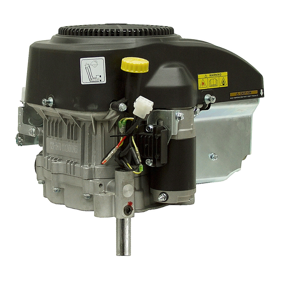
- Page 1 RESIDENTIAL PRODUCTS RIDING PRODUCT ENGINE SERVICE MANUAL LC1P92F (452cc)
- Page 2 An electronic version of this service manual is available on the Toro Dealer Portal. We are hopeful that you will find this manual a valuable addition to your service shop. If you have any questions or comments regarding this...
- Page 3 Chapter 1 – General Service Information Chapter 2 - Engine Service / Maintenance Chapter 3 - Engine Disassembly and Service Chapter 4 - Electrical...
- Page 4 NOTES:...
-
Page 5: Table Of Contents
Chapter 1 – General Service Information Safety Service Rules Engine Model / Serial Number Location Engine Fastener Torque Specification General Specifications Engine Specifications Troubleshooting... -
Page 6: Safety
This manual is intended as a service and repair manual only. The safety instructions provided herein are for troubleshooting, service, and repair of the Toro engine. The Toro operator’s manual contains safety information and operating tips for safe operating practices. -
Page 7: Service Rules
Service Rules 1. Only use genuine Toro parts and lubrication products. 2. Always install new gaskets, O-rings and seals when assembling engine. 3. Always torque fasteners to specification and in sequence. 4. Always lubricate friction components with clean engine oil or engine assembly lube when assembling engine. -
Page 8: Engine Fastener Torque Specification
Engine Fastener Torque Specifications Oil Drain Valve 7 ft-lbs (10 Nm) Oil Filter Adaptor Bolt 31 ft-lbs (42 Nm) Spark Plug 20 ft-lbs (28 Nm) Connecting Rod Bolts 12 ft-lbs (16 Nm) Crankcase Cover Bolt 20 ft-lbs (28 Nm) Fuel Pump Asm. Mounting Bolts 7 ft-lbs (10 Nm) Breather Plate Bolts 7 ft-lbs (10 Nm) -
Page 9: General Specifications
General Specifications Model 1P92F-1 Type Single Cylinder, 4-Stroke, Forced Air Cooling, OHV Bore X Stroke (mm) 92×68 Displacement (cc) Compression Ratio 8.8 :1 Lubrication Oil Pump with Oil Filter Starting Electric Rotation Counter Clockwise (From P.T.O. Side) Ignition System Transistorized Magneto Ignition Air Cleaner Foam and Paper Fuel Type... -
Page 10: Engine Specifications
Engine Specifications Part Item Standard Service Limit 3350 – 3450 RPM - Operating RPM Engine 1700 – 2000 RPM - Idle RPM 0.00393” (0.10 mm) - Cylinder Head Warpage Sleeve Taper / Out of Round 3.6220” - 3.6224” (92-92.01 mm) 3.6259”... -
Page 11: Troubleshooting
Troubleshooting Hard Starting / Poor Running - Incorrect Fuel (Level, Age, Octane, Ethanol Content) - Fuel System Contamination and / or Debris in Carburetor - Incorrect Oil Level - Weak Battery / Charging System - Spark Plug (Incorrect Gap, Fouled, Loose or Faulty) - Air Filter Restriction - Air Intake System Leaks - Ignition Coil to Flywheel Gap Incorrect... - Page 12 NOTES:...
- Page 13 Chapter 2 – Engine Service / Maintenance Engine Oil Change Procedure Air Cleaner Service Spark Plug Service Valve Clearance Inspection and Adjustment Engine Governor – Zero Point Setting Engine Idle Speed / Operating RPM Adjustment Fuel Filter Replacement...
-
Page 14: Engine Oil Change Procedure
Engine Oil Change Procedure 1. Warm engine, then remove the ignition key before changing the engine oil. 2. Drain oil through the drain valve / hose into an approved container. 3. When oil has drained completely, close the oil drain valve. Remove the oil drain hose and wipe up any excess oil on the frame. -
Page 15: Air Cleaner Service
Air Cleaner Service Remove the ignition key before servicing the air cleaner. Thoroughly clean the air filter area. Loosen the (2) Cover Knobs and remove the air cleaner cover. Remove the (2) air cleaner retainer nuts and the air cleaner retainer plate. Carefully remove and separate the foam and paper filter elements from the air cleaner housing. -
Page 16: Spark Plug Service
Spark Plug Service NOTE: Spark plugs of the wrong size or incorrect heat range can cause severe engine damage. High Voltage Ignition Systems can be Dangerous - Use Caution when Servicing Ignition Systems 1. Disconnect the spark plug boot and thoroughly clean the spark plug area. 2. -
Page 17: Valve Clearance Inspection And Adjustment
Valve Clearance Inspection and Adjustment NOTE: Valve clearance inspection and adjustment must be done with the engine cold 1. Rotate Engine to TDC (top-dead-center) of the compression stroke. 2. Remove the valve cover. Be sure both valves are completely closed and the decompression arm is not holding the valve open. -
Page 18: Engine Governor - Zero Point Setting
Engine Governor – Zero Point Setting 1. Loosen but do not remove the governor arm pinch bolt and nut. 2. Move the governor arm to fully open the throttle valve. Firmly hold the governor arm in this position. 3. Rotate the governor shaft fully clockwise and secure it in this position with a pair of pliers. 4. -
Page 19: Engine Idle Speed / Operating Rpm Adjustment
Engine Idle Speed 1. Start the engine and allow it to warm to normal operating temperature. 2. With the throttle control in the idle position and the engine idling, adjust the throttle stop screw (A) to achieve the recommended engine idle speed. Engine Idle Speed: 1700 - 2000 RPM Engine Operating RPM Adjustment 1. -
Page 20: Fuel Filter Replacement
Fuel Filter and Replacement - Fuel is Extremely Flammable - Use Extreme Caution When Servicing the Fuel System 1. Place a proper fuel drain pan under the fuel filter area. 2. Release the fuel filter / fuel hose clamps (A) and slide them away from the filter. 3. - Page 21 Chapter 3 - Engine Disassembly and Service Engine Service – Upper End 18-25 Air Cleaner and Muffler Exploded View Starter, Flywheel and Engine Cover Exploded View Carburetor and Linkage Exploded View Carburetor Exploded View Cylinder Head Exploded View and Service Information Valve Spring / Valve Seat / Cylinder Head Specifications Valve Stem / Valve Guide Specifications Valve Seat Reconditioning...
-
Page 22: Engine Service - Upper End
Engine Service – Upper End Air Cleaner and Muffler Exploded View Muffler Air Cleaner Retainer Nuts Heat Shield 6 ft-lbs (8 Nm) Spacer Gasket Air Filter Asm. Carburetor Mounting Nuts / Bolts Gasket 7 ft-lbs (10 Nm) Fuel Solenoid... -
Page 23: Starter, Flywheel And Engine Cover Exploded View
Starter, Flywheel and Engine Cover Exploded View Flywheel Nut 81 ft-lbs (110 Nm) Fan Shroud Bolts 7 ft-lbs (10 Nm) Ignition Coil and Alternator Bolts 7 ft-lbs (10 Nm) Ignition Coil Alternator Starter Bolts 20 ft-lbs (28 Nm) -
Page 24: Carburetor And Linkage Exploded View
Carburetor and Linkage Exploded View Governor Arm Governor Spring Governor Rod Throttle Control Asm. Throttle Rod Choke Rod Choke Bell Crank Governor Pinch Bolt... -
Page 25: Carburetor Exploded View
Carburetor Exploded View Needle Valve Float Gasket Bowl Bowl Bolt Gasket 6 ft-lbs (8 Nm) Solenoid Screw 3.5 ft-lbs (5 Nm) Fuel Solenoid... -
Page 26: Cylinder Head Exploded View And Service Information
Cylinder Head Exploded View and Service Information Shield Studs 23 ft-lbs (31 Nm) Cylinder Head Gasket 7.5 ft-lbs Lock Nut (10 Nm) 11 ft-lbs (15 Nm) Cylinder Head Bolt Torque Sequence: 1. Initially Torque the (4) Cylinder Head Bolts in a Crisscross Pattern to 10 ft-lbs (14 Nm). 2. -
Page 27: Valve Spring / Valve Seat / Cylinder Head Specifications
Valve Spring Free Length Specification Standard Service Limit 1.555 - 1.594” 1.535” (39.5-40.5 mm) (39.0 mm) Valve Seat Width Inspection Remove carbon deposits from the combustion chamber. Inspect the valve seats for pitting or other damage. Valve Seat Width Specification: Standard Service Limit 0.03149 - 0.0393”... -
Page 28: Valve Stem / Valve Guide Specifications
Valve Stem Inspection Inspect each valve for face irregularities, bending or abnormal wear. Valve Stem Diameter Specification Standard Service Limit 0.2584 - 0.2590” 0.2579” Intake (6.565-6.58 mm) (6.550 mm) 0.2577 - 0.2583” 0.2571” Exhaust (6.545-6.56 mm) (6.530 mm) Valve Guide Inspection Ream the exhaust valve guide to remove any carbon deposits before measuring. -
Page 29: Valve Seat Reconditioning
Valve Seat Reconditioning 1. Thoroughly clean the combustion chamber and valve seats to remove carbon deposits. 2. Apply a light coat of Prussian Blue or erasable felt-tipped marker ink to the valve faces. 3. Properly install valves, springs and keepers. Manually open the valves, then and snap them closed against their seats several times. -
Page 30: Engine Service - Lower End
Engine Service – Lower End Crankcase Exploded View and Service Information 7 ft-lbs (10Nm) A Oil Seal B Breather Reed Valve Asm. C Governor Shaft D Oil Seal Pin / Clip Washer G Bearing (2) H Balance Shaft (LH and RH) Thrust Washer Camshaft K Bearing... -
Page 31: Crankshaft / Piston / Exploded View And Service Info
Crankshaft / Piston / Exploded View and Service Info Connecting Rod Bolts Piston Asm. 12 ft-lbs (16 Nm) Crankshaft Connecting Rod Bearing Governor Exploded View Weight Governor Gear Slider / Spool Shaft Clip Washer... -
Page 32: Piston Connecting Rod Exploded View And Information
Piston Connecting Rod Exploded View and Service Information Assembly: Mark Install Rings with Orientation Mark “UP” Stagger the piston ring gap as shown: Top Ring Second Ring Top Ring Oil Ring Second Ring Oil Ring Check, refer to Piston Piston Pin Piston Pin Circlip: Install the circlip gap in the 12:00 Position (circlip gap... -
Page 33: Camshaft And Balance Shaft Timing
Camshaft and Balance Shaft Timing 1. Install crankshaft. 2. Align crankshaft and camshaft timing marks and install camshaft. 3. Align the left balance shaft timing marks and install the left balance shaft. 4. Align the right balance shaft timing marks and install the right balance shaft. Camshaft Crankshaft Timing Marks... -
Page 34: Crankcase / Piston / Cylinder / Pin Specifications
Crankshaft Bearing Free Play Clean the bearing in solvent and dry it. Spin the bearing by hand and check for play. Replace the bearing if it is noisy or has excessive free play. Piston Pin OD Standard Service Limit 0.7871 - 0.7873” 0.7834”... -
Page 35: Piston / Piston Ring Specifications
Piston Skirt Outside Diameter Measure and the piston skirt outside diameter 10mm from the skirt base and 90°to piston pin hole. Standard Service Limit 3.620 - 3.621” 3.6196” (91.96-91.975 mm) (91.940 mm) Piston to Cylinder Clearance Specification Standard Service Limit 0.00098 - 0.0017”... -
Page 36: Piston Ring / Connecting Rod Specifications
Piston Ring End Gap Standard Service Limit 0.0059 - 0.0118” 0.0137” (0.15-0.30 mm) (0.35 mm) Use the piston to position the rings squarely 1” down from the top of the cylinder. Connecting Rod Small End ID Standard Service Limit 0.79 - 0.788” 0.7881”... -
Page 37: Crankshaft Specifications
Crankshaft Pin OD Standard Service Limit 1.417 - 1.4165” 1.415” (35.966-35.981 mm) (35.946 mm) Connecting Rod Big End Side Clearance Standard Service Limit 0.00079 - 0.0138” 0.00157” (0.02-0.35 mm) (0.4 mm) Connecting Rod Big End Oil Clearance 1. Clean oil from the crankshaft and connecting rod. 2. -
Page 38: Camshaft Specifications
Camshaft Lobe Specifications Standard Service Limit 1.282 - 1.284” 1.276” Intake (32.563-32.603 mm) (32.40 mm) 1.262 - 1.264” 1.256” Exhaust (32.049-32.099 mm) (31.9 mm) Camshaft Journal OD Standard Service Limit 0.6298 - 0.6293” 0.6266” (15.996-15.984 mm) (15.916 mm) Check the camshaft bearing journal for scoring, wear or damage. NOTE: Verify that the decompression mechanism moves freely. - Page 39 Chapter 4 – Electrical System Information Ignition Coil Gap Adjustment Ignition Coil Resistance Inspection Spark Testing Fuel Solenoid Charging System Specifications...
-
Page 40: Ignition Coil Gap Adjustment
Ignition Coil Gap Adjustment High Voltage Ignition Systems can be Dangerous - Use Caution when Servicing Ignition Systems 1. Install the ignition coil and lightly tighten the ignition coil mounting bolts. 2. Rotate engine so ignition coil is aligned with the magnet portion of the flywheel. 3. -
Page 41: Spark Testing
Spark Testing - Fuel is Extremely Flammable - Use Extreme Caution When Servicing the Fuel System - High Voltage Ignition Systems can be Dangerous - Use Caution when Servicing Ignition Systems 1. Remove spark plug cap from the spark plug. 2. -
Page 42: Charging System Specifications
Charging System Specifications Charge Coil(s) Air Gap 0.011- 0.019” (.3-.5 mm) Measure Between the Magnet Area of the Flywheel and the Charge Coil Legs No Load DC Voltage Output @ 3000 RPM 14.5 +/- .5 Volts DC Measure Across Battery Terminals No Load AC Voltage Output @ 3000 RPM 30 VAC Measure Across Stator Leads –... - Page 43 NOTES:...
- Page 44 RESIDENTIAL PRODUCTS Form Number: 492-9234...