Advertisement
Quick Links
T
ECHNICAL INFORMATION
Model No.
Description
C
ONCEPT AND MAIN APPLICATIONS
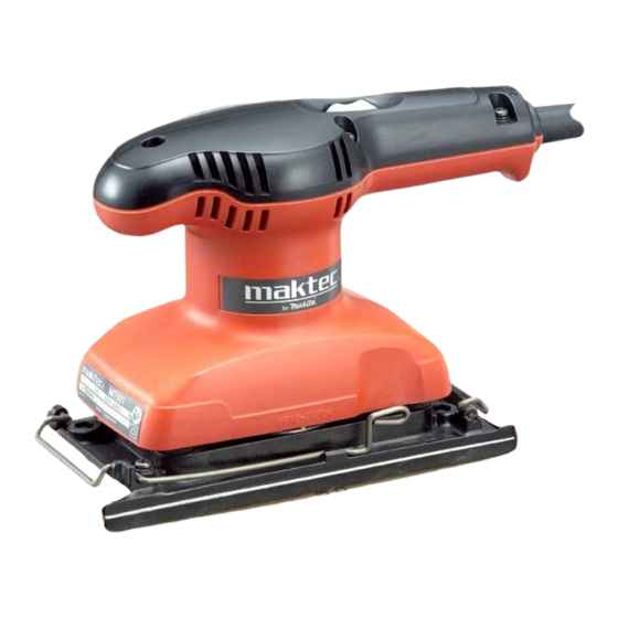
Model MT921 has been developed on the design concept;
"easy-to-control" is the key factor to a finishing sander with
strong marketability.
The main benefits are:
Ergonomic grip contoured for easy handling
both in single- and double-handed operation
Industrial performance and durability at less expense
S
pecification
Voltage (V)
110
120
220
230
240
Pad size: mm (")
Abrasive paper size: mm (")
Orbits per minute: min.
Strokes per minute: min.
Paper fastening
system
Double insulation
Power supply cord: m (ft)
Net weight: kg (lbs)
S
tandard equipment
Abrasive paper 93-120 ....................... 1 pc
Note: The standard equipment for the tool shown above may vary by country.
O
ptional accessories
Abrasive paper 93-60
Abrasive paper 93-80
Abrasive paper 93-100
Abrasive paper 93-120
Abrasive paper 93-150
MT921
Finishing Sander
Cycle (Hz)
Current (A)
1.7
50/60
1.6
50/60
0.9
50/60
0.9
50/60
0.8
50/60
93 x 185 (3-5/8 x 7-1/4)
= opm
-1
= spm
-1
Hook & loop
Clamp
Continuous Rating (W)
Input
180
---
180
180
180
93 x 228 (3-5/8 x 9)
12,000
24,000
No
Yes
Yes
2.0 (6.6)
1.3 (2.9)
PRODUCT
L
H
Dimensions: mm (")
Length (L)
214 (8-3/8)
Width (W)
92 (3-5/8)
Height (H)
147 (5-3/4)
Max. Output (W)
Output
45
60
45
60
45
60
45
60
45
60
P 1/ 5
W
Advertisement

Related Manuals for Makita Maktec MT921


Summary of Contents for Makita Maktec MT921
- Page 1 ECHNICAL INFORMATION PRODUCT P 1/ 5 Model No. MT921 Description Finishing Sander ONCEPT AND MAIN APPLICATIONS Model MT921 has been developed on the design concept; "easy-to-control" is the key factor to a finishing sander with strong marketability. The main benefits are: Ergonomic grip contoured for easy handling both in single- and double-handed operation Dimensions: mm (")
-
Page 2: Necessary Repairing Tools
P 2/ 5 epair CAUTION: Unplug the machine for safety before repair/ maintenance in accordance with the instruction manual! [1] NECESSARY REPAIRING TOOLS Code No. Description Use for Bearing setting pipe 18-10.2 Removing Armature 1R027 Removing Ball bearing 1R269 Bearing extractor [2] Disassembly/ Assembly [2]-1. - Page 3 P 3/ 5 epair [2] Disassembly/ Assembly Fig. 9 [2]-1. Armature (cont.) DISASSEMBLING 1R027 9) Remove Armature from Bearing box by striking the armature shaft end. When it is difficult to remove Armature in the above manner, put Bearing box on U-shape base of arbor press, then press down Ball bearing 6200LLB of Armature using 1R027 and arbor press.
-
Page 4: Circuit Diagram
P 4/ 5 ircuit diagram Fig. D-1 Color index of lead wires' sheath Black White Orange Purple Field Brush holder A Brush holder B Terminal block (if used) Viewed from Top cover Switch Brush Brush holder A holder B Noise suppressor (if used) Blue color is used for some countries. -
Page 5: Wiring Diagram
P 5/ 5 iring diagram Fig. D-2 Field lead wire Field lead wire Connect Insulated terminals A and B Fix Field lead wires with Brush holders A and B. with Lead wire holders And set each Brush holders carefully in to prevent slacks near place so as not to put on Areas A and B Armature.