Table of Contents
Advertisement
Form No. 3364-606 Rev A
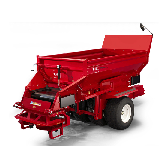
MH-400 Material Delivery Unit
Model No. 44930--Serial No. 310000001 and Up
Model No. 44931--Serial No. 310000001 and Up
Model No. 44933--Serial No. 310000001 and Up
Model No. 44934--Serial No. 310000001 and Up
Model No. 44937
Model No. 44938
Original Instructions (EN)
Register your product at www.Toro.com
Advertisement
Table of Contents
Troubleshooting

Related Manuals for Toro MH-400


Summary of Contents for Toro MH-400
- Page 1 Form No. 3364-606 Rev A MH-400 Material Delivery Unit Model No. 44930--Serial No. 310000001 and Up Model No. 44931--Serial No. 310000001 and Up Model No. 44933--Serial No. 310000001 and Up Model No. 44934--Serial No. 310000001 and Up Model No. 44937 Model No.
-
Page 3: Table Of Contents
Purchase Date and Distributor Information ...............1 Specifications ........................2 Introduction........................4 How to Use the Operator’s Manual................4 Message Boxes ......................4 About the MH-400 Material Delivery Unit ................5 Features and Benefits....................5 Spreading Options .....................5 Twin Spinner Option..................5 Cross Conveyor Option..................5 Swivel Kit Option ....................5 MH Processor Option..................5... - Page 4 How to Prepare the Electrical Connections on EH Model........21 Operating Instructions....................22 Connecting the MH-400 to the Tow Vehicle............22 How to Disconnect the MH-400 from the Tow Vehicle ........... 23 Operating the Hydraulic Control Valves on SH Models .......... 23 Left Valve....................... 23 Center Valve ....................
- Page 5 Hydraulic Schematic For EH Model.................45 Electrical Schematic For SH Model .................46 Electrical Schematic For EH Model .................47 How to Wash the MH-400..................48 Long-term Storage of the MH-400 ................48 How to Transport the MH-400 .................48 Troubleshooting ......................49 General Troubleshooting ..................49 Brake Troubleshooting.....................50 Electrical Troubleshooting................50...
- Page 6 Figure 15: Control Pendant For EH Models ............24 Figure 16: Open rear gate / close rear gate, side view ........... 27 Figure 17: Raise the MH-400 to unload into a smaller machine ......28 Figure 18: Positioning the Pendant Swing Arm............28 Figure 19: Twin Spinner Disc Settings ..............
-
Page 7: Product Identification
Information Model Name and Serial Number Date of purchase The MH-400 model number and serial number are located on a Model, Serial Number plate mounted on the left side of the front panel (Figures 1 and 2).When you contact an... -
Page 8: Specifications
Specifications : These specifications are subject to MPORTANT change without notice. They are provided for reference purposes only. Contact an authorized Toro Tires distributor for up-to-date or additional information. 82.5 x 40 x 40.25 cm – 10 ply Size (33 x 16 x 16.1 in) -
Page 9: Figure 3: Mh-400 Dimensions
(78 ft the hopper Maximum belt speed 2.9 rpm or 18 m (60 ft) per minute Vibration Under normal operating conditions, the MH-400 does not produce vibrations over 2.0 m/s (6.6 ft/s ) to the operator’s arms, or over 0.5 (1.6 ft/s... -
Page 10: Introduction
This Operator’s Manual contains message boxes that are Read this Operator’s Manual carefully before operating the labelled Danger, Warning, Caution, and Important. MH-400 Material Delivery Unit. Keep it in an accessible These boxes indicate potential safety concerns or location. equipment damage, and operating and servicing information. -
Page 11: About The Mh-400 Material Delivery Unit
• The option caddy allows one person to install or with a 270 degree range from the rear of the MH-400. The remove an option in minutes—no heavy lifting swivel action is useful for filling ditches and sand traps. -
Page 12: Hydraulic Power Pack Option
Use this option to supply hydraulic pressure to the operating this machine. They are recommended if you do MH-400 and its equipment when the tow vehicle has only not have a heavy-duty tow vehicle equipped with four- a PTO (power take-off unit). The power pack is a self- wheel drive. -
Page 13: Safety Instructions
Do not allow untrained people or persons under 16 roads. years of age to operate the MH-400. • Do not operate the MH-400 if you have any doubts Safe Operating Practices about any aspect of its operation. • The MH-400 has different balance, weight, and •... -
Page 14: Hoses And Lines
Another option is to tow a Be careful when installing or removing it. fully loaded MH-400 to a spot near the job and then load smaller machines from the MH-400 to complete the job. If an option is mounted on the rear, or the load has moved For best results, use a tow vehicle with a fixed to the rear, the MH-400 becomes heavier at the back. -
Page 15: Unloading
400 in the fully raised position. This increases the risk of tipping over. The MH-400 has a safe range for traveling with options Unloading attached as shown by the green section in decal (see safety decals on page 15). -
Page 16: Hills
See safety decals on page 12. Traveling across steep hills with the unit fully loaded could result in tipping over, or a loss of traction for the MH-400 or tow vehicle. Always travel straight up and down hills—do not travel sideways or diagonally. -
Page 17: Tongue Weight
Safety Attire Each time you operate the MH-400: Tongue Weight • The tongue is the area on the MH-400 where the hitch Wear safety glasses or safety goggles with side connects to the tow vehicle. The weight of the tongue shields. -
Page 18: Safety Decals
MH-400. If problems result, this may violate local Safety Decals regulations, void the warranty, or cause injury or death. Important safety decals on your MH-400 indicate areas : Install the hydraulic cylinder with potential safety hazards. Replace any decal that... - Page 19 119-6850: Shear hazard 115-2047: Warning - Hot Locking bar up 93-9899: Crush hazard Install the cylinder lock when extended 119-6822: Floor Conveyer On - Off 93-9852: Warning – Lift Cylinder 119-6821: Do not travel with cross conveyor extended Always center cross conveyor when traveling 119-6830: Base Unit 119-6804: Thrown object hazard Stay a safe distance from the machine...
- Page 20 119-6832: Adjustments 119-6831: Use ISO VG-68 Hydraulic fluid 90 L (23.8 U.S. gal) 119-6833: Consult Operator’s Manual Maximum loads for MH-400 Maximum load—11,800 lb (5,352 kg) Vehicle weight—3,000 lb (1,361 kg) Maximum gross vehicle weight—14,800 lb (6,713 kg) 119-6823: Hydraulic Controls 119-6851: Warning –...
- Page 21 119-6834: Consult Operator’s Manual Maximum load for optional caddy 1500 lb (680 kg) 119-6845: Tailgate Height Indicator Setup Instructions Page 15...
- Page 22 119-6825: Safe range for traveling with options attached Consult Operator’s Manual Page 16 Setup Instructions...
-
Page 23: Setup Instructions
An authorized Toro distributor normally sets up the MH- 5. Insert the front edge of the option up and under the 400 Material Delivery Unit at the time of purchase. See rear of the MH-400 into the front clamps on the the Setup Manual for more information. brackets. -
Page 24: How To Connect The Option's Hydraulics
3. Ensure that the connectors are pushed all the way in and are securely locked in place. To connect the hydraulic hoses to the option control valve on the MH-400 fender: 4. With the tow vehicle hydraulics operating, pull back on the option control lever, and ensure that the option is operating properly. -
Page 25: How To Install The Cross Conveyor
2. Position the swivel kit so that its two mounting 1. Install the cross conveyor into the quick-attach brackets face toward the rear (away from the brackets at the rear of the MH-400 (see How to MH-400). Mount the Options on page 17). -
Page 26: How To Install The Mh Processor
Note – Removing the power to the solenoid will force the the hopper of the processor. MH-400 SH to use hydraulic power from the tow vehicle. When not using the MH-400 SH, always disconnect the : Use your option caddy to lift... -
Page 27: How To Prepare The Electrical Connections On Eh Model
Figure 12: Control Pendant on Tow Vehicle Mount Connect the MH-400 EH electrical harness into the tow-vehicle’s plug. 3. Plug the control pendant cord into the MH-400 EH 2. Install the control pendant assembly into the pendant connector located at the end of the swing appropriate mount (swing arm or tow vehicle). -
Page 28: Operating Instructions
Note - You may have to relieve the pressure in the hoses 2. Adjust the hitch height by turning the jack stand of the MH-400 connecting to the tow vehicle, to ensure a handle to keep the MH-400 level. completed connection. -
Page 29: How To Disconnect The Mh-400 From The Tow Vehicle
MH-400. • To turn on the option, pull back on the control lever. 8. Lift the MH-400 with the jack until the weight is off the tow vehicle’s draw bar. Pull out the hitch pin. • To turn off the option, return the control lever to the center position. -
Page 30: Operating The Hydraulic Controls And Options On Eh Models
Figure 14: Hydraulic control valves A. Conveyor belt direction (left control valve) B. Raise and lower MH-400 (center control valve) C. Options on and off (right control valve) D. Option hydraulic quick connectors Operating the Hydraulic Controls and Figure 15: Control Pendant For EH Models... -
Page 31: Conveyor Belt
Bin Raise/Lower Lower Bin • To raise the MH-400, press and hold the “raise bin” button on the control pendant until the desired height is reached, then release it. • To lower the MH-400, press and hold the “lower Raise Bin bin”... -
Page 32: Option Control
: Do not press the “option start” button MPORTANT on the control pendant without an option connected. This can damage the hydraulics on the MH-400. Storing/Recalling a Preset on EH Models The control pendant has the ability to store 6 pre-set speeds for the belt and the option. -
Page 33: Loading Material
For materials such as landscaping ties or fertilizer bags, load from the rear by 3. If desired, raise the rear of the MH-400. This unloads placing the material on the conveyor belt and setting the material at a different angle, and allows quick hydraulics in the load position. -
Page 34: Unloading Into Smaller Machines
Unloading Into Smaller Machines Operating the Pendant Swing Arm on 1. Raise the rear of the MH-400 high enough to EH Models accommodate the smaller machine underneath (Figure 16). The pendant swing arm holds the control pendant when mounted on the MH-400. The following procedure 2. -
Page 35: Mh-400 Factory Recommended Settings Guide
Always test new materials by spreading them in an open 8. When the MH-400 is empty, turn off the hydraulics area away from people. before transporting the MH-400. 4. Start the tow vehicle and turn on the tow vehicle Note – When driving over uneven terrain, raise the MH- hydraulics. -
Page 36: Mh 400 Eh Twin Spinner Suggested Application Guide
Application Spinner Floor Base Disc Application Spread Application Rear Gate Factor Speed Control Setting Setting Width Ultra Light Maximum 25mm (1”) 12.2m (40’) Light Maximum 76mm (3”) 12.2m (40’) Medium Maximum 76mm (3”) 6.7m (22’) Medium Maximum 76mm (3”) 3.4m (11’) Heavy Heavy Maximum 127mm (5”) - Page 37 Disc Settings Figure 19: Twin Spinner Disc Settings Base Settings Figure 20: Twin Spinner Base Settings Operating Instructions Page 31...
-
Page 38: How To Operate The Cross Conveyor
Note – For SH models the on/off pendant switch stops the 5. Re-install the safety pins. MH-400 conveyor belt, not the cross conveyor. 6. On SH models adjust the speed of the cross conveyor 7. When finishing using the cross conveyor, always with the hydraulic lever on the right. -
Page 39: How To Operate The Swivel Kit
1. Turn on the tow vehicle hydraulics. Note – When traveling over uneven terrain, raise the MH-400 to the maximum safe traveling range. This 2. Open the adjustable section of the rear gate on the provides more ground clearance for the cross conveyor. -
Page 40: How To Operate The Option Caddy (1)
5. Transport the option to the rear of the MH-400 and raise it into position for mounting. 6. Install the option into the quick-attach brackets on the rear of the MH-400 (see How to Mount the Options on page 16). -
Page 41: How To Operate The Option Caddy (2)
227 kg storage stands. (500 lb). Do not carry people on it. 12. Transport the option to the rear of the MH-400 and raise it into position for mounting. 8. Position the caddy against the rear of the option. -
Page 42: How To Operate The Hydraulic Power Pack
1. Engage the tow vehicle’s PTO. Do not exceed the and instructions. maximum speed of 540 rpm. : Do not use the electric brakes on roads. 2. Test the MH-400 by operating a control valve, such MPORTANT as the lift cylinders. Page 36... -
Page 43: Maintenance Instructions
Tires and Wheels Maintenance Instructions The recommended tire pressure is 172 kPa (25 psi), Rely on an authorized Toro distributor to help you use or as recommended by the tire manufacturer. and maintain the MH-400 for best performance. Check for excessive wear or visible damage. -
Page 44: Belt And Rear Gate Seals
1. Jack up the MH-400 securely. • Inspect the magnet arm for any loose or worn parts. 2. Ensure that the wheel and drum rotate freely. -
Page 45: Lubrication
How to Measure Brake Amperage “lubriplate,” on the: The brake system amperage is the total current that is • brake anchor pin drawn by all brakes on the MH-400. To measure the total • amperage: actuating arm bushing and pin •... - Page 46 Tighten both locking nuts before running the MH-400. : Do not adjust the belt’s rear drive roller. MPORTANT 4. Load the MH-400 with material and run the load It is set to factory specifications. Contact your through until empty. Repeat multiple times.
-
Page 47: How To Tension The Conveyor Belt
How to Tension the Conveyor Belt How to Adjust the Conveyor Drive Chain 1. Park the MH-400 on level ground with the rear gate If the conveyor drive chain is loose, it needs to be and feed gate at least 6.25 mm (¼ in) off the floor tightened (Figure 32). -
Page 48: Grease And Lubrication Schedule
Parts Catalog or Toro distributor for part numbers.) Floor drive chain Every 2 months or 25 hours Alternate fluids: If the Toro fluid is not available, other fluids may be used provided they meet all the following : Do not over-grease, or the bearing seals MPORTANT material properties and industry specifications. - Page 49 One bottle is sufficient for 4-6 gal (15-21l) of hydraulic oil. Order part no. 44-2500 from your authorized Toro Distributor. : Toro recommends that the fluid used in MPORTANT the hydraulic components be maintained at ISO Cleanliness Code 18/13 per SAE J1165. This code allows a maximum of 2,500 p/ml greater than 5 µm and a maximum of 80 p/ml greater than 15 µm.
-
Page 50: Hydraulic Schematic For Sh Model
Hydraulic Schematic For SH Model Figure 34: Hydraulic schematic For SH Model 1. Electrically activated (12 V) hydraulic valve assembly 2. Note – SV1 and SV2 are energized simultaneously (turning conveyor belt off) 3. Forward/reverse floor motor valve 4. Floor motor 5. -
Page 51: Hydraulic Schematic For Eh Model
Hydraulic Schematic For EH Model Figure 35: Hydraulic schematic For EH Model 1. Tow vehicle reservoir 2. Tow vehicle pump 3. Quick coupler (pressure) 4. Quick coupler (return) 5. Conveyor belt motor 6. Lift Cylinders 7. Twin Spinner 8. Cross Conveyor 9. -
Page 52: Electrical Schematic For Sh Model
Electrical Schematic For SH Model Figure 36: Electrical schematic For SH Model 1. Solenoid assembly 2. Wire side of male on/off pendant plug on MH-400 3. Wire side of female on/off pendant plug on pendant switch 4. Rear of on/off pendant switch 5. -
Page 53: Electrical Schematic For Eh Model
Electrical Schematic For EH Model Figure 37: Electrical schematic For EH Model 1. Wiring Loom 2. Power Lead 3. Connection to Power Supply 4. Option Forward Lead 5. Bin Lower Lead 6. Bin Raise Lead 7. Floor Reverse Lead 8. Floor Forward Lead 9. -
Page 54: How To Wash The Mh-400
4. Grease all fittings and pivot points. Wipe off any 2. Remove the control pendant on the EH models. excess lubricant. 3. Wash the body of the MH-400 with warm water and 5. Lightly sand any painted areas that are scratched, a mild detergent. -
Page 55: Troubleshooting
Troubleshooting General Troubleshooting If the problem still occurs after all the checks listed below have been completed, contact an authorized Toro distributor for service. Symptom Cause The belt control valve is in the center position. The belt is incorrectly tensioned. -
Page 56: Brake Troubleshooting
If the high amperage reading drops to zero by troubleshooting the electric brakes. unplugging the MH-400, then the short is in the MH-400 wiring. If the amperage reading remains high with all the brakes magnets disconnected, the short is in the MH-400 wiring. - Page 57 Symptom Cause Improper brake adjustment Improper synchronization Locking brakes Faulty controller Loose, bent, or broken brake components Out-of-round brake drums (distorted shape) Faulty controller Broken wires Intermittent brakes Loose connections Faulty ground Under adjustment Harsh brakes Improper synchronization Faulty controller Under adjustment Lack of lubrication Noisy brakes...
-
Page 58: Mh-400 Maintenance Record
MH-400 Maintenance Record Service Performed Date Notes Page 52 Troubleshooting... - Page 59 Troubleshooting Page 53...