
Related Manuals for Toro CT2240


Summary of Contents for Toro CT2240
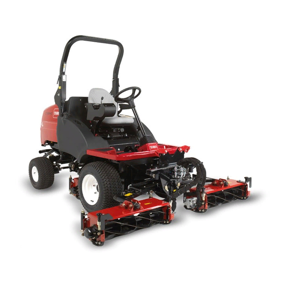
- Page 1 Form No. 3439-307 Rev B CT2240 Compact Triple 4-Wheel Drive Turf Mower Model No. 30654—Serial No. 405600000 and Up *3439-307* Register at www.Toro.com. Original Instructions (EN)
- Page 2 Whenever you need service, genuine Toro parts, or additional information, contact an Authorized Service Dealer or Toro Customer Service and have the model and serial numbers of your product ready. Figure 1 identifies the location of the model and serial numbers on the product.
-
Page 3: Table Of Contents
Contents Engine Maintenance ........... 38 Engine Safety ........... 38 Checking the Engine Overheat Warning Safety ............... 4 System............38 General Safety ........... 4 Servicing the Air Cleaner ........38 Safety and Instructional Decals ......5 Servicing the Engine Oil and Filter ....39 Setup .............. -
Page 4: Safety
Safety Storage Safety..........51 Preparing the Traction Unit ....... 51 Preparing the Engine ........52 This machine has been designed in accordance with Troubleshooting ............53 EN ISO 5395. General Safety This product is capable of amputating hands and feet and of throwing objects. -
Page 5: Safety And Instructional Decals
Safety and Instructional Decals Safety decals and instructions are easily visible to the operator and are located near any area of potential danger. Replace any decal that is damaged or missing. decal70-13-072 decal111-0773 70-13-072 111-0773 1. Jacking point 1. Warning—crushing of fingers, force applied from side. decal70-13-077 70-13-077 1. - Page 6 decal111-3901 111-3901 1. Transmission fluid—read the Operator's Manual. decal111-3566 111-3566 1. Falling, crushing hazard—ensure that the operator platform decal111-3902 111-3902 latch is engaged before operating. 1. The fan can cut your hand; warning 2. Hot surfaces; read the Operator's Manual. decal111-3567 111-3567 1.
- Page 7 decal134-1807 134-1807 1. Slope indicator 7. Raise 2. Right cutting unit controls 8. Fast 9. Engine speed 3. Center cutting unit controls 4. Left cutting unit controls 10. Slow 11. Horn 5. Lower/float 6. Transport...
- Page 8 decal111-8098 111-8098 Note: This machine complies with the industry standard stability test in the static lateral and longitudinal tests with the maximum recommended slope indicated on the decal. Review the instructions for operating the machine on slopes in the Operator’s Manual as well as the conditions in which you would operate the machine to determine whether you can operate the machine in the conditions on that day and at that site.
- Page 9 decal111-7249 111-7249 1. Daily service interval 6. Check hydraulic fluid level 11. Check cutting unit setting 16. Lubrication points for daily interval 2. 50 hour service interval 7. Check fuel level 12. Check engine coolant level 17. Lubrication points for 50 hour interval 3.
-
Page 10: Setup
Setup Media and Additional Parts Description Qty. Operator's Manual Read the manuals before operating the machine. Engine owner’s manual Store all documentation in a safe place for future use. Note: Determine the left and right sides of the machine from the normal operating position. -
Page 11: Product Overview
Controls Product Overview Control Panel Components g025164 Figure 3 1. Front cutting units 4. Operator's seat 5. Engine hood 2. Control arm 3. Steering wheel 6. Rear cutting unit g014418 Figure 4 1. Parking brake switch 11. Horn button 2. Limited lift in reverse 12. - Page 12 g014421 Figure 7 1. Parking brake g014419 Figure 5 Emergency Brake 1. Weight transfer control In the event of service brake failure, turn the ignition off to bring the mower to a standstill. WARNING Application of the emergency brake activates front wheel brakes of the mower;...
- Page 13 Transport Latches Always raise the cutting units to the transport position and secure with the transport latches and safety locks when travelling between work areas (Figure 10). g014547 Figure 8 1. Throttle control lever Traction Pedals Forward travel: Press the forward travel pedal to increase forward travel speed.
- Page 14 g014549 Figure 11 Operator Seat WARNING Damaged operator seat mechanisms may cause the seat to become loose, which may cause you to lose control of the machine. • Never operate the mower if the operator seat mechanisms are damaged or if the seat does not remain securely in position once adjusted and locked.
- Page 15 Warning Systems Low Battery Charge Warning Light The battery charge warning light illuminates when low Engine Coolant Overheating Warning Light battery charge occurs (Figure 15). The engine coolant warning light illuminates, the horn is actuated, and the cutting units stop (Figure 13).
- Page 16 Ignition Key Fuel Gauge The fuel gauge shows the amount of fuel in the tank 0 = Engine off (Figure 20). I = Engine run/Auxiliary on II = Engine pre-heat III = Engine start CAUTION If you leave the key in the ignition switch, g014558 someone could accidently start the engine Figure 20...
- Page 17 Cutting Unit Drive Switch Indicator Light This light illuminates when the cutting unit drive switch is in the F position and the ignition ORWARD EVERSE key is turned to position I (Figure 23). g014561 Figure 23 1. Cutting unit drive switch indicator light...
-
Page 18: Specifications
32 L (8.5 US gallons) Attachments/Accessories A selection of Toro approved attachments and accessories is available for use with the machine to enhance and expand its capabilities. Contact your Authorized Service Dealer or authorized Toro distributor or go to www.toro.com/en-gb for a list of all approved attachments and accessories. -
Page 19: Before Operation
• Before mowing, always inspect the machine to temperatures) ensure that the cutting units are in good working Toro Premium Engine oil is available from your condition. distributor in either 15W-40 or 10W-30 viscosity. • Inspect the area where you will use the machine... -
Page 20: Checking The Cooling System
CAUTION If the engine has been running, the pressurized, hot coolant can escape and cause burns. • Do not open the radiator cap when the engine is running. • Use a rag when opening the radiator cap, and open the cap slowly to allow steam to escape. -
Page 21: Adding Fuel
Adding Fuel DANGER In certain conditions, fuel is extremely Service Interval: Before each use or daily flammable and highly explosive. A fire or Use only clean, fresh diesel fuel with low (<50 ppm) explosion from fuel can burn you and others or ultra-low (<15 ppm) sulfur content. -
Page 22: Hydraulic Fluid Specifications
A machine using the recommended replacement fluid requires less frequent fluid and filter changes. Alternative fluids: If Toro PX Extended Life Hydraulic Fluid is not available, you may use another conventional, petroleum-based hydraulic fluid having specifications that fall within the listed range for all the following material properties and that it meets industry standards. -
Page 23: Checking The Torque Of The Wheel Nuts
Move the locking latch handle toward the front Front Axle 23 x 0.7 bar (10 1.4 bar (20 1.7 bar (25 of the mower as the platform nears the fully 10.5 - 12 psi) psi) psi) BKT turf lowered position. pattern Note: This ensures that the latch hooks clear... -
Page 24: During Operation
• You can start the engine only with the cutting unit drive Look behind and down before backing up to be switch in the O position. sure of a clear path. • Use care when approaching blind corners, shrubs, WARNING trees, or other objects that may obscure your vision. -
Page 25: Slope Safety
and use the seat belt when operating the machine – If possible, keep the cutting units lowered to with the roll bar in the raised position. the ground while operating on slopes. Raising the cutting units while operating on slopes can •... -
Page 26: Adjusting The Center Cutting Unit Height-Of-Cut Correction
WARNING Contact with hot or moving parts can result in personal injury. Keep all body parts away from any hot or moving parts of the engine. g014557 Figure 29 1. Engine pre-heat indicator light WARNING An illuminated warning light could indicate a serious problem that could lead to personal injury. -
Page 27: Adjusting The Cutting Unit Auto Limited Lift
To raise the cutting units, operate the lift control Auto limited lift in reverse causes the cutting units switches in an upward direction and hold in to rise automatically to the limited lift position when position 3. If the cutting unit drive switch is in reversing. -
Page 28: Clearing The Cutting Units
Clearing the Cutting Units Release the valve locknut 1/2 turn counterclockwise and hold (Figure 33). Rotate the valve hand wheel (Figure WARNING counterclockwise to reduce weight transfer or Never attempt to rotate the cutting units by clockwise to increase weight transfer. hand. -
Page 29: Operating Tips
• Ensure that the seat belt and mountings are in safe working order. • Wear the seat belt when the roll bar is raised and no seat belt when the roll bar is lowered. Important: The roll bar is an integral safety device. -
Page 30: After Operation
increase the height of cut. Check that the reels are WARNING not in heavy contact with their bedknives. Mechanical or hydraulic jacks may fail to support the machine and cause serious injury. Driving the Machine in Transport Use jack stands when supporting the Mode machine. -
Page 31: Towing The Machine
To transport the machine: Install a M12 x 40 mm long setscrew with washer into the hole in the center of the motor end plate • Ensure that your vehicle, hitch, safety chains, and (Figure 37). trailer are adequate for the load you are pulling and that they meet all local traffic regulations for your area. - Page 32 g014451 Figure 39 1. Front wheel motor 3. Washer M12 2. Hex plug 4. Setscrew M12 x 40 mm Identify the left front wheel motor disc brake assembly and repeat the previous g014450 Figure 38 procedure. 1. Transmission bypass valves Remove the wheel chocks.
-
Page 33: Maintenance
Note: Determine the left and right sides of the machine from the normal operating position. Note: To obtain an electrical schematic or a hydraulic schematic for your machine, visit www.toro.com/en-gb. Maintenance Safety • Support the machine with jack stands whenever you work under the machine. - Page 34 Maintenance Service Maintenance Procedure Interval • Drain moisture from the fuel tank and the hydraulic-fluid tank. Every 200 hours • Check the condition of the battery. • Check the condition of and clean the battery. Every 250 hours • Check the battery cable connections. •...
-
Page 35: Daily Maintenance Checklist
Daily Maintenance Checklist Duplicate this page for routine use. For the week of: Maintenance Check Item Mon. Tues. Wed. Thurs. Fri. Sat. Sun. Check the safety interlock operation. Check the brake operation. Check the engine-oil and fuel levels. Check the air-filter restriction indicator. Check the radiator and screen for debris. -
Page 36: Service Interval Chart
Service Interval Chart g025069 Figure 40... -
Page 37: Lubrication
Lubrication Replace any damaged grease fittings. Grease all cutting unit grease points and ensure that sufficient grease is injected such that clean Greasing the Bearings, grease is seen to escape from the roller end caps. This provides visible evidence that the roller seals Bushings, and Pivots have been purged of grass and debris and ensures maximum working life. -
Page 38: Engine Maintenance
Engine Maintenance Service the primary air-cleaner filter only when the service indicator (Figure 43) requires it. Changing the air filter before it is necessary only increases the Engine Safety chance of dirt entering the engine when the filter is removed. •... -
Page 39: Servicing The Engine Oil And Filter
Insert the new filter by applying pressure to the outer rim of the element to seat it in the canister. Do not apply pressure to the flexible center of the filter. Clean the dirt ejection port located in the removable cover. Remove the rubber outlet valve from the cover, clean the cavity and replace the outlet valve. -
Page 40: Fuel System Maintenance
Bleeding the Fuel System Fuel System Maintenance You must bleed the fuel system before starting the engine if any of the following situations have occurred: • Initial start up of a new machine. DANGER • Engine has ceased running due to lack of fuel. Under certain conditions, diesel fuel and fuel vapors are highly flammable and explosive. -
Page 41: Replacing The Fuel Filter
Replacing the Fuel Filter Electrical System Maintenance Service Interval: Every 400 hours Important: Replace the fuel filter canister periodically to prevent wear of the fuel injection Electrical System Safety pump plunger or the injection nozzle, due to dirt in the fuel. •... -
Page 42: Servicing The Battery
Servicing the Battery Drive System Maintenance Service Interval: Every 250 hours DANGER Changing the Transmission Battery electrolyte contains sulfuric acid which is fatal if consumed and causes severe Oil Filter burns. Service Interval: After the first 50 hours • Do not drink electrolyte and avoid contact Every 500 hours with skin, eyes, or clothing. -
Page 43: Changing The Hydraulic Return Filter
Changing the Hydraulic Checking the Rear Wheel Return Filter Alignment Service Interval: After the first 50 hours Service Interval: Every 500 hours Every 500 hours To prevent excessive tire wear and ensure safe machine operation, the rear wheels must be correctly Remove the return filter. -
Page 44: Inspecting The Transmission Control Cable And Operating Mechanism
Inspecting the Cooling System Transmission Control Maintenance Cable and Operating Cooling System Safety Mechanism • Swallowing engine coolant can cause poisoning; Service Interval: Every 250 hours keep out of reach from children and pets. Check the condition and security of the cable and •... - Page 45 collected on other parts of the machine (Figure 54) with compressed air. g018023 Figure 52 1. Engine cover 3. Oil cooler 2. Oil cooler release clip g004137 Figure 54 Clean the screen thoroughly with compressed 1. Radiator air. Pivot the latch inward to release the oil cooler Pivot the oil cooler back into position and secure (Figure 53).
-
Page 46: Belt Maintenance
Belt Maintenance Controls System Maintenance Check the condition and tension of the alternator belt after the first day of operation and every 100 operating hours thereafter. Checking the Tensioning the Alternator Forward/Reverse Travel Belt Pedal Action Service Interval: After the first 8 hours With the engine shut off, operate the forward and reverse travel pedals through the full range of Every 100 hours... -
Page 47: Checking The Parking Brake Interlock Switch
Checking the Parking Brake Hydraulic System Interlock Switch Maintenance Shut off the engine. Hydraulic System Safety Engage the parking brake. Turn the ignition key to position I. The parking • Seek immediate medical attention if fluid is injected brake indicator light should illuminate. into skin. -
Page 48: Servicing The Hydraulic System
Servicing the Hydraulic Checking the Hydraulic System Fluid Overheat Warning System Service Interval: Every 500 hours Note: Keep water away from electrical components. Service Interval: Every 500 hours Use a dry cloth or brush to clean such areas. This procedure is best carried out when the hydraulic fluid is warm (not hot). -
Page 49: Cutting Unit Maintenance
Cutting Unit Maintenance 80-grade carborundum paste Part No. 0.45 kg (1 lb) 63-07-088 Blade Safety 11.3 kg (25 lb) 63-07-086 A worn or damaged blade or bedknife can break, and a piece could be thrown toward you or bystanders, resulting in serious personal injury or death. •... -
Page 50: Grinding The Cutting Units
Dispose of hazardous substances grind the bedknife. All such grinding should be carried correctly. out by your authorized Toro distributor on a quality, Do not dispose of batteries with a separate well-maintained reel/bedknife grinding machine collection mark into general waste. -
Page 51: Cleaning
Clean the battery, terminals, and posts with a wire brush and baking soda solution. Coat the cable terminals and battery posts with Grafo 112X skin-over grease (Toro Part No. 505-47) or petroleum jelly to prevent corrosion. Slowly recharge the battery every 60 days for 24 hours to prevent lead sulfation of the battery. -
Page 52: Preparing The Engine
Preparing the Engine Drain the engine oil from the oil pan and install the drain plug. Remove and discard the oil filter. Install a new oil filter. Refill the oil pan with designated quantity of motor oil. Start the engine and run it at idle speed for approximately 2 minutes. -
Page 53: Troubleshooting
Troubleshooting Problem Possible Cause Corrective Action There are areas of uncut grass at the 1. You are turning too tightly. 1. Increase the turning radius overlap between cutting units. 2. The machine slides sideways when 2. Mow up/down the slope. travelling across the face of a slope. - Page 54 Problem Possible Cause Corrective Action There is scalping of the turf. 1. The undulations are too severe for the 1. Use floating cutting units. height of cut setting. 2. The height of cut is too low. 2. Raise the height of cut. There is excessive bedknife wear.
- Page 55 Problem Possible Cause Corrective Action There is no machine movement in forward 1. The parking brake is engaged. 1. Disengage the parking brake. or reverse. 2. The fluid level is low. 2. Fill the reservoir to the correct level. 3. The reservoir has the wrong kind of 3.
- Page 56 4. The pressure relief valve is jammed 4. Have the relief valve pressure open or wrongly set. checked. Consult your authorized Toro distributor. 5. A cutting unit is jammed. 5. Clear any jams as necessary.
- Page 57 Notes:...
- Page 58 Notes:...
- Page 59 The Toro Company (“Toro”) respects your privacy. When you purchase our products, we may collect certain personal information about you, either directly from you or through your local Toro company or dealer. Toro uses this information to fulfil contractual obligations - such as to register your warranty, process your warranty claim or to contact you in the event of a product recall - and for legitimate business purposes - such as to gauge customer satisfaction, improve our products or provide you with product information which may be of interest.
- Page 60 Countries Other than the United States or Canada Customers who have purchased Toro products exported from the United States or Canada should contact their Toro Distributor (Dealer) to obtain guarantee policies for your country, province, or state. If for any reason you are dissatisfied with your Distributor's service or have difficulty obtaining guarantee information, contact your Authorized Toro Service Center.