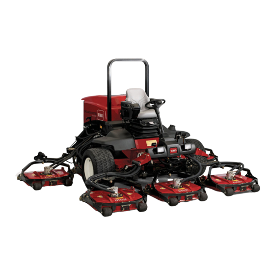
Toro Groundsmaster 4500-D Operator's Manual
Traction unit
Hide thumbs
Also See for Groundsmaster 4500-D:
- Service manual (474 pages) ,
- Operator's manual (92 pages) ,
- Installation instructions manual (28 pages)
Table of Contents

Related Manuals for Toro Groundsmaster 4500-D


Summary of Contents for Toro Groundsmaster 4500-D
- Page 1 Form No. 3417-109 Rev A Groundsmaster ® 4500-D and 4700-D Traction Unit Model No. 30881—Serial No. 401333001 and Up Model No. 30882—Serial No. 401333001 and Up *3417-109* A Register at www.Toro.com. Original Instructions (EN)
- Page 2 Authorized Service specific Declaration of Conformity (DOC) sheet. Dealer or Toro Customer Service and have the model and serial numbers of your product ready. Figure 1 identifies the location of the model and serial numbers WARNING on the right front frame member of the product.
-
Page 3: Table Of Contents
Contents Maintenance ............51 Recommended Maintenance Schedule(s) ... 51 Daily Maintenance Checklist......52 Safety ............... 4 Service Interval Chart ........53 General Safety ........... 4 Pre-Maintenance Procedures ......54 Engine Emission Certification ......4 Pre-Maintenance Safety ........54 Safety and Instructional Decals ......5 Preparing the Machine for Maintenance.... -
Page 4: Safety
Safety Replacing the Hydraulic Filters ......75 Checking the Hydraulic Lines and Hoses............76 This machine has been designed in accordance with Cutting Unit Maintenance ........76 EN ISO 5395:2013 and ANSI B71.4-2012. Removing the Cutting Units ......76 Installing the Cutting Units ........ 77 Servicing the Front Roller ......... -
Page 5: Safety And Instructional Decals
Safety and Instructional Decals Safety decals and instructions are easily visible to the operator and are located near any area of potential danger. Replace any decal that is damaged or missing. decal93-7818 93-7818 decal107-1971 1. Warning—read the Operator's Manual for instructions on 107–1971 torquing the blade bolt/nut to 115 to 149 N∙m (85 to 110 ft-lb). - Page 6 decal117-2718 117-2718 decal117-4765 117-4765 1. Read the Operator's Manual. 2. Do not use starting aids. decal117-4766 117-4766 1. Cutting/dismemberment hazard; fan—stay away from moving parts, keep all guards and shields in place. decal117-4763 117-4763 1. To engage the parking 2. To disengage the parking brake, secure the brake brake, disengage the pedals with the locking pin,...
- Page 7 decal121-3887 121-3887 1. Read the Operator’s Manual. decal120-8947 120-8947 1. Warning—read the 4. If the roll bar is raised, decal136-2931 Operator’s Manual. wear the seat belt. 136-2931 2. There is no rollover 5. If the roll bar is lowered, For Groundsmaster 4500 Only protection when the roll do not wear the seat belt.
- Page 8 decal125-4605 125-4605 1. Power seat (10 A) 6. Power supplied (10 A) decal125-4606 2. Work light (10 A) 7. GM4700 controller (2 A) 125-4606 3. Engine (10 A) 8. Power supplied (7.5 A) 1. Read the Operator’s Manual for information on 4.
- Page 9 decal121-3627 121-3627 1. Height-of-cut settings decal127-6447 127-6447 (Affix over Part No. 112-5297 for CE* for 4500 series machines) Note: This machine complies with the industry standard stability test in the static lateral and longitudinal tests with the maximum recommended slope indicated on the decal. Review the instructions for operating the machine on slopes in the Operator's Manual and the conditions in which the machine is being operated to determine whether the machine can be operated in the conditions on that day and at that site.
- Page 10 decal127-6448 127-6448 (Affix over Part No. 112-5297 for CE* for 4700 series machines) Note: This machine complies with the industry standard stability test in the static lateral and longitudinal tests with the maximum recommended slope indicated on the decal. Review the instructions for operating the machine on slopes in the Operator's Manual and the conditions in which the machine is being operated to determine whether the machine can be operated in the conditions on that day and at that site.
-
Page 11: Setup
Setup Loose Parts Use the chart below to verify that all parts have been shipped. Procedure Description Qty. Replace the warning decal (CE Warning decal machines only). Hood-latch bracket Rivet Install the hood latch (CE machines Washer only). Screw (1/4 x 2 inches) Locknut (1/4 inch) –... - Page 12 Remove the 2 rivets securing the hood-latch bracket to the hood (Figure 3). Remove the hood-latch bracket from the hood. g012630 Figure 5 1. Hood latch Screw the bolt into the other arm of the hood-latch bracket to lock the latch in position g012628 Figure 3 (Figure...
-
Page 13: Adjusting The Roller Scraper (Optional)
Adjusting the Roller Installing the Mulching Scraper (Optional) Baffle (Optional) No Parts Required No Parts Required Procedure Procedure Thoroughly clean debris from the mounting holes The optional rear roller scraper is designed to work on the rear wall and left wall of the chamber. best when there is an even gap of 0.5 to 1 mm (0.020 to 0.040 inch) between the scraper and roller. -
Page 14: Preparing The Machine
Product Overview Controls Preparing the Machine No Parts Required Procedure Park the machine on a level surface. Lower the cutting units. Engage the parking brake. g009979 Shut off the engine and remove the key. Figure 9 Check the tire pressure before use; refer to 1. - Page 15 down on the right brake pedal while engaging the toe or decrease the engine speed in 100 rpm increments. pedal. To release the parking brake, press 1 of the Hold down the switch to automatically move to High brake pedals until the parking brake latch retracts. or Low idle, depending on which end of the switch you press.
- Page 16 Power Point Use the power point (Figure 12) to power optional 12 V electrical accessories. g024916 Figure 13 1. Weight gauge 4. Seat-back adjustment lever g036845 2. Weight adjustment lever 5. Armrest adjustment knob Figure 12 3. Seat adjustment lever 1.
- Page 17 Using the InfoCenter LCD Display InfoCenter Icon Description SERVICE DUE Indicates when scheduled service The InfoCenter LCD display shows information about should be performed your machine, such as the operating status, various diagnostics and other information about the machine Hours remaining until service (Figure 14).
- Page 18 InfoCenter Icon Description (cont'd.) InfoCenter Icon Description (cont'd.) Start the engine. Operator should change to indicated state The PTO is on. Symbols are often combined to form sentences. Some The cruise control is on. examples are shown below Shut off the engine Operator should put machine in neutral Engine...
- Page 19 Description Left Cutting Unit Refer to the Service Manual To access the InfoCenter menu system, press the or your authorized Toro menu access button while at the main screen. This Center Cutting Unit distributor for more information brings you to the main menu. Refer to the following...
- Page 20 0000 or 1234. g028522 Figure 16 If you changed the PIN code and forgot the code, contact your Authorized Toro Distributor for assistance. To enter the PIN code, press the center button From the M , use the center button to...
- Page 21 When finished with the Protected Menu, press the left Viewing and Changing the Protected Menu Settings button to exit to the Main Menu, then press the left In the Protected Menu, scroll down to Protect button to exit to the Run Menu. Settings.
-
Page 22: Specifications
Specifications g198614 Figure 17... -
Page 23: Machine Specifications
88 kg (195 lb) Attachments/Accessories A selection of Toro approved attachments and accessories is available for use with the machine to enhance and expand its capabilities. Contact your Authorized Service Dealer or Distributor or go to www.Toro.com for a list of all approved attachments and accessories. -
Page 24: Before Operation
Checking the Engine-Oil Operation Level Note: Determine the left and right sides of the machine from the normal operating position. Before you start the engine and use the machine, check the oil level in the engine crankcase; refer to Checking the Engine-Oil Level (page 58). -
Page 25: Filling The Fuel Tank
• Do not use fuel additives. • Contact your Authorized Toro Distributor if you wish for more information on biodiesel. Petroleum Diesel Cetane rating: 45 or higher Sulfur content: Ultra-low sulfur (<15 ppm) -
Page 26: Checking The Tire Pressure
Adding Fuel Checking the Tire Pressure Service Interval: Before each use or daily The correct air pressure in the tires is 138 kPa (20 psi). Important: Maintain the recommended pressure in all tires to ensure a good quality of cut and proper machine performance. -
Page 27: Adjusting The Roll Bar
not use the seat belt when the roll bar is in the lowered position. Lowering the Roll Bar Important: Lower the roll bar only when necessary. g033359 Important: Ensure that the seat is secured with Figure 21 the seat latch. Rear Wheels WARNING Failing to maintain proper torque of the wheel... -
Page 28: Adjusting The Height Of Cut
Adjusting the Height of Cut Install the bolt finger-tight. Repeat steps through for each side Important: The cutting units often cut adjustment. approximately 6 mm (1/4 inch) lower than a reel Torque all 3 bolts to 41 N∙m (30 ft-lb). Always cutting unit with the same bench setting. -
Page 29: Checking The Blade-Stopping Time
If this time is greater than 7 seconds, Using the high-lift blade with the mulching adjust the braking valve. Call your authorized Toro baffle could cause the blade to break, distributor for assistance in making this adjustment. -
Page 30: Choosing Accessories
Choosing Accessories Angle Sail Blade High-Lift, Parallel-Sail Mulching Baffle Roller Scraper Blade (Do not use with the mulching baffle) Recommended in most May work well in light or Has been shown to Grass Cutting—1.9 to Can be used whenever 4.4 cm (3/4 to 1-3/4 applications sparse turf improve dispersion and... -
Page 31: During Operation
Never carry passengers on the machine and keep • Use accessories and attachments approved by bystanders and pets away from the machine The Toro® Company only. during operation. • Operate the machine only in good visibility. Avoid Rollover Protection System holes or hidden hazards. -
Page 32: Starting The Engine
include surveying the site to determine which starter failure may result. If the engine fails slopes are safe for machine operation. Always to start after 15 seconds, turn the key to use common sense and good judgment when the O position, check the controls and performing this survey. -
Page 33: Diesel Particulate Filter Regeneration
• Press the PTO switch to prepare cutting units Passive regeneration occurs continuously while for operation. the engine is running—run the engine at full engine speed when possible to promote DPF Use the joystick to raise the cutting units off the regeneration. - Page 34 DPF Ash Accumulation • When enough ash accumulates, the engine computer sends information to the InfoCenter • The lighter ash is discharged through the exhaust in the form of an engine fault to indicate the system; the heavier ash collects in the soot filter. accumulation of ash in the DPF.
- Page 35 Types of Diesel Particulate Filter Regeneration Types of diesel particulate filter regeneration that are performed while the machine is operating: Type of Regeneration Conditions that cause DPF regeneration DPF description of operation Passive Occurs during normal operation of the machine at •...
- Page 36 Types of diesel particulate filter regeneration that require you to park the machine: (cont'd.) Type of Regeneration Conditions that cause DPF regeneration DPF description of operation Recovery Occurs because the operator ignored requests for • When the reset-standby/parked or recovery a parked regeneration and continued operating the machine, adding more soot to the DPF regeneration icon...
- Page 37 press the right button to select the Technician entry DPF Operation Table (cont'd.) (Figure 33). State Description Reset Regen The engine computer is running a reset regeneration. The engine computer is requesting that Parked Stby you run a parked regeneration. Parked Regen You initiated a parked regeneration request and the engine computer is...
- Page 38 Assist DPF Regeneration • The icon displays in the InfoCenter while the reset regeneration is processing. • The engine computer adjusts engine settings to • Whenever possible, do not shut off the engine or raise the exhaust temperature. reduce engine speed while the reset regeneration •...
- Page 39 g227304 g224394 Figure 38 Figure 40 Press the right button to change the inhibit Note: If the engine exhaust temperature is too low, regeneration setting from On to Off (Figure the InfoCenter displays A #186 (Figure 41) to DVISORY or from Off to On (Figure 39).
- Page 40 Parked or Recovery Regeneration regeneration required—power takeoff disabled #189 (Figure 45). DVISORY • When the engine computer requests either a parked regeneration or a recovery regeneration, the regeneration request icon (Figure 42) displays in the InfoCenter. g224398 Figure 45 Important: Perform a parked regeneration to restore the PTO function;...
- Page 41 Important: Perform a recovery regeneration Move the machine outside to an area away from to restore the PTO function; refer to Preparing combustible materials. to Perform a Parked or Recovery Regeneration Park the machine on a level surface. (page 41) Performing a Parked or Recovery Regeneration (page 41).
- Page 42 At the DPF checklist screen, verify that the parking brake is engaged and that the engine speed is set to low idle (Figure 53). g224402 g224407 g224629 Figure 51 At the V screen, verify that you g227679 ERIFY FUEL LEVEL Figure 53 have 1/4 tank of fuel if you are performing the parked regeneration or 1/2 tank of fuel if you are...
- Page 43 The InfoCenter displays the I NITIATING Check Message and Corrective Action Table message (Figure 55). EGEN (cont'd.) g224411 Corrective Action: Start and run the engine. g227681 Figure 55 Corrective Action: Run the engine to warm the coolant The InfoCenter displays the time to complete temperature to 60°C (140°F).
- Page 44 Canceling a Parked or Recovery Regeneration displays A #183 (Figure 58). Press the DVISORY left button to exit to the home screen. Use the Parked Regen Cancel or Recovery Regen Cancel setting to cancel a running parked or recovery regeneration process. Access the DPF Regeneration menu (Figure 60).
-
Page 45: Understanding The Operating Characteristics Of The Machine
Understanding the Operating the Operating Characteristics Engine-Cooling Fan of the Machine The engine cooling fan is normally controlled by the machine. The machine can reverse the fan to blow Practice driving the machine because it has a debris off the rear screen. Under normal operating hydrostatic transmission, and its characteristics are conditions, the machine controls the fan speed different than many turf maintenance machines. -
Page 46: Using Cruise Control
Using Cruise Control Operating Tips The cruise-control switch locks in the pedal position to Operating the Machine maintain the desired ground speed. Pressing the rear of the switch turns the cruise control off, the middle • Start the engine. If the A function is position of the switch enables the cruise-control turned off, run it at H... - Page 47 Resolving After-Cut Appearance Checking the Condition of the Mower Deck Refer to the After-cut Appearance Troubleshooting Guide available at www.Toro.com. Ensure that the cutting chambers are in good condition. Straighten any bends in the chamber components to ensure correct blade tip/chamber Using Proper Mowing Techniques clearance.
-
Page 48: After Operation
Securing the Cutting Units After Operation Ensure that the PTO is disengaged. After Operation Safety Park the machine on a level surface. Engage the parking brake. • Clean grass and debris from the cutting units, mufflers, and engine compartment to help prevent Fully raise the cutting units. -
Page 49: Hauling The Machine
With the cutting units lowered, slip the loop of the lanyard into the slot in the reinforcement plate of the roller support (Figure 66). g036666 g225685 g225485 Figure 67 Figure 66 1. Bypass valves 1. Reinforcement-plate slot 2. Lanyard loop (roller support) Rotate each valve 3 turns counter-clockwise to open and allow the oil to bypass internally. -
Page 50: Locating The Tie-Down Points
Locating the Tie-Down Points Note: Use properly-rated DOT-approved straps in 4 corners to tie down the machine. • On each side of the frame by the operator’s platform • On the rear bumper g208989 Figure 68 g036665 Figure 69... -
Page 51: Maintenance
Setting the Inhibit Regen (page 38). Note: Download a free copy of the electrical or hydraulic schematic by visiting www.Toro.com and searching for your machine from the Manuals link on the home page. Note: Determine the left and right sides of the machine from the normal operating position. -
Page 52: Daily Maintenance Checklist
Maintenance Service Maintenance Procedure Interval • Disassemble, clean, and assemble the soot filter of the DPF or clean the soot filter if engine faults 3251 3720 0, or 3720 16 display in the Every 6,000 hours InfoCenter. • Drain and clean the fuel tank. •... -
Page 53: Service Interval Chart
For the week of: Maintenance Check Item Monday Tuesday Wednesday Thursday Friday Saturday Sunday Lubricate all the grease fittings. Touch up any damaged paint. Check the glow plug and injector nozzles if starting is hard, there is excess smoke, or rough running is noted. Immediately after every washing, regardless of the interval listed. -
Page 54: Pre-Maintenance Procedures
Pre-Maintenance Important: Do not support the machine at the wheel-drive motors. Keep the lifting equipment Procedures clear of hydraulic tubing and hoses. Pre-Maintenance Safety • Before adjusting, cleaning, repairing, or leaving the machine, do the following: – Park the machine on a level surface. –... -
Page 55: Opening The Hood
Opening the Hood Accessing the Hydraulic Lift Compartment Tilt the hood to access the chassis as shown in Figure Tilt the seat to access the hydraulic lift compartment as shown in Figure g036674 g036706 Figure 73 Figure 74... -
Page 56: Lubrication
Lubrication • Steering-cylinder ball joints (2) as shown in Figure Greasing the Bearings and Bushings Service Interval: Every 50 hours (also after every washing). Grease specification: No. 2 lithium grease The grease fitting locations and quantities are as follows: • Brake-shaft pivot bearings (5) as shown in Figure g009706... -
Page 57: Engine Maintenance
Engine Maintenance • Cutting-unit spindle-shaft bearings (2 per cutting unit) as shown in Figure 79 Note: You can use either fitting, whichever is Engine Safety more accessible. Pump grease into the fitting until a small amount appears at the bottom of the •... -
Page 58: Servicing The Engine Oil
Preferred oil: SAE 15W-40 (above 0°F) • Alternate oil: SAE 10W-30 or 5W-30 (all temperatures) Toro Premium Engine Oil is available from your Authorized Toro Distributor in either 15W-40 or 10W-30 viscosity grades. See the parts catalog for part numbers. - Page 59 Crankcase Oil Capacity If the engine oil level is above the Full mark, change the engine oil. Approximately 5.7 L (6 US qt) with the filter. The best time to check the engine oil is when the engine is cool before it has been started for the day. Changing the Engine Oil and Filter If it has already been run, allow the oil to drain back down to the sump for at least 10 minutes before...
-
Page 60: Servicing The Diesel-Oxidation Catalyst (Doc) And The Soot Filter
Manual for information on disassembling and assembling the diesel-oxidation catalyst and the soot filter of the DPF. Inspecting the Fuel Lines Refer to your authorized Toro distributor for and Connections diesel-oxidation catalyst and the soot filter replacement parts or service. -
Page 61: Servicing The Fuel-Water Separator
Servicing the Fuel-Water Replacing the Fuel-Filter Canister Separator Service Interval: Every 400 hours—Replace the fuel-filter canister. Replace the fuel-filter canister as shown in Figure g198661 Figure 87 Draining Water from the Fuel/Water Separator Service Interval: Before each use or daily—Drain water or other contaminants from the fuel filter/water separator Drain water from the fuel/water separator as shown... -
Page 62: Servicing The Fuel Filter
Servicing the Fuel Filter Service Interval: Every 400 hours Clean the area around the fuel-filter head (Figure 90). g036687 Figure 91 1. Fitting (fuel-pickup tube) 4. Rubber bushing 2. Hose clamp 5. Screen 3. Fuel supply hose Separate the hose from the fitting (Figure 91). -
Page 63: Electrical System Maintenance
Coat the battery posts and cable connectors with severe burns. Grafo 112X (skin-over) grease (Toro Part No. 505-47) or petroleum jelly to prevent corrosion. • Do not drink electrolyte and avoid contact with skin, eyes, or clothing. -
Page 64: Locating The Fuses
WARNING WARNING Incorrect battery cable routing could Charging the battery produces gasses damage the machine and cables, causing that can explode. sparks. Sparks can cause the battery Never smoke near the battery and keep gasses to explode, resulting in personal sparks and flames away from battery. -
Page 65: Drive System Maintenance
Drive System Maintenance g225611 Figure 97 g009985 Figure 95 Checking for End-Play in 1. Latch 2. Right storage box the Planetary Drives Replace the open fuse(s) as needed (Figure 96). Service Interval: Every 400 hours There should be no end-play in the planetary drives/drive wheels (i.e., the wheels should not move when you pull or push them in a direction parallel to the axle). -
Page 66: Checking The Planetary Gear-Drive Lubricant
Repeat step for the other drive wheel. If either wheel moves, contact your authorized g225606 Figure 100 Toro distributor to have the planetary drive rebuilt. 1. Check-plug hole 2. Check plug Checking the Planetary If the oil level is low, remove the fill plug at the 12 o’clock position and add oil until it begins to... - Page 67 Filling the Planetary-Gear-Drive with Lubricant Through the fill-plug hole, slowly fill the planetary with 0.65 L (22 fl oz) of high quality SAE 85W-140 wt gear lube. Important: If the planetary fills before the 0.65 L (22 fl oz) of oil is added, wait 1 hour or install the plug and move the machine approximately ten feet to distribute the oil through the brake system.
-
Page 68: Checking The Rear Axle And Gearbox For Leaks
Checking the Rear Axle and Gearbox for Leaks Service Interval: Before each use or daily Visually inspect the rear axle and rear-axle gearbox for leaks. g009716 Figure 106 1. Check plug 2. Fill plug Changing the Rear-Axle Lubricant Service Interval: After the first 200 hours Every 800 hours Lubricant specification: high-quality SAE 85W-140 g036704... -
Page 69: Checking The Rear-Axle-Gearbox Lubricant
Checking the Rear Wheel lube or until the lubricant is up to the bottom of the hole. Toe-In Install the check plug. Service Interval: Every 800 hours/Yearly (whichever comes first) Checking the Park the machine on a level surface, engage the Rear-Axle-Gearbox parking brake, lower the mower decks, shut off the engine, and remove the key. -
Page 70: Cooling System Maintenance
Cooling System revolution and tighten the clamp at the connected end of the tie rod. Maintenance Install the ball joint in the axle-case support, tighten the nut finger-tight, and measure the toe-in. Cooling System Safety Repeat procedure if necessary. • Swallowing engine coolant can cause poisoning;... -
Page 71: Cleaning The Cooling System
Clean the screen thoroughly of all debris. g198662 Figure 112 g009702 Figure 111 1. Rear-screen latch 1. Expansion tank Thoroughly clean both sides of the oil cooler and the radiator with compressed air (Figure 113). Check the coolant level in the radiator. The radiator should be filled to the top of the filler Note: Start from the front and blow the debris... -
Page 72: Brake Maintenance
Brake Maintenance damage to components and compacts debris. Close the rear screen and secure it with the Adjusting the Service latch. Brakes Adjust the service brakes when there is more than 25 mm (1 inch) of free travel of the brake pedal, or when the brakes do not work effectively. -
Page 73: Belt Maintenance
(Available in 19 L (5 US gallon) pails or 208 L (55 US gallon) drums. See the Parts Catalog or your authorized Toro distributor for part numbers). Alternative fluids: If the Toro fluid is not available, other conventional, petroleum-based fluids may be used, provided they meet all the following material properties and industry specifications. - Page 74 Mobil EAL EnviroSyn 46H is the only synthetic biodegradable fluid approved by Toro. This fluid is compatible with the elastomers used in Toro hydraulic systems and is suitable for a wide-range of temperature conditions. This fluid is compatible with conventional mineral oils, but for...
-
Page 75: Changing The Hydraulic Fluid
Service Interval: After the first 200 hours Service Interval: Every 800 hours Every 800 hours If the fluid becomes contaminated, contact your Toro Distributor because the system must be flushed. Use Toro replacement filters Part No. 94-2621 for Contaminated fluid looks milky or black when the rear (mower decks) of the machine and Part No. -
Page 76: Checking The Hydraulic Lines And Hoses
Cutting Unit Maintenance Removing the Cutting Units Park the machine on a level surface, engage the parking brake, lower the cutting units, shut off the engine, and remove the key. Disconnect and remove the hydraulic motor g036709 from the cutting unit (Figure 119). -
Page 77: Installing The Cutting Units
Installing the Cutting Units Assembling the Front Roller Press the first bearing into the roller housing Move the cutting unit into position in front of the (Figure 121). Press on the outer race only or machine. equally on the inner and outer race. Slide the cutting unit-carrier frame onto the Insert the spacer (Figure... -
Page 78: Blade Maintenance
Blade Maintenance Rotate the marked end of the blade to the 3 and 9 o’clock positions (Figure 122) and measure the heights. Blade Safety Compare the 12 o’clock measured height to the height-of-cut setting. It should be within 0.7 mm A worn or damaged blade can break, and a piece (0.030 inch). -
Page 79: Removing And Installing The Cutting-Unit Blade(S)
Park the machine on a level surface, raise the Replace the blade if it hits a solid object, is out cutting units, engage the parking brake, put the of balance, or is bent. Always use genuine Toro traction pedal in , put the PTO lever... - Page 80 Note: Remove the blades and sharpen them on a grinder. After sharpening the cutting edges, install the blade with the anti-scalp cup and blade bolt; refer to Removing and Installing the Cutting-Unit Blade(s) (page 79). g004653 Figure 125 1. Cutting edge 3.
-
Page 81: Storage
1. Spindle plug 2. Spindle sprocket a wire brush and baking soda solution. Coat the cable terminals and battery posts with Grafo 112X skin-over grease (Toro Part No. 505-47) or petroleum jelly to prevent corrosion. Slowly recharge the battery every 60 days for 24 hours to prevent lead sulfation of the battery. - Page 82 Notes:...
- Page 83 The Way Toro Uses Information Toro may use your personal information to process warranty claims, to contact you in the event of a product recall and for any other purpose which we tell you about. Toro may share your information with Toro's affiliates, dealers or other business partners in connection with any of these activities. We will not sell your personal information to any other company.
- Page 84 Countries Other than the United States or Canada Customers who have purchased Toro products exported from the United States or Canada should contact their Toro Distributor (Dealer) to obtain guarantee policies for your country, province, or state. If for any reason you are dissatisfied with your Distributor's service or have difficulty obtaining guarantee information, contact the Toro importer.