Husqvarna Automower 305 Technical Manual
Hide thumbs
Also See for Automower 305:
- Technical manual (86 pages) ,
- Operator's manual (80 pages) ,
- Workshop manual (52 pages)
Table of Contents
Advertisement
Advertisement
Chapters
Table of Contents
Troubleshooting

Related Manuals for Husqvarna Automower 305


Summary of Contents for Husqvarna Automower 305
- Page 1 TEC H N ICAL MANUAL ® H U SQVARNA AUTOMOWE R 305/308 GARDE NA R40LI/R70LI...
-
Page 3: Table Of Contents
5.20 Replacing the rear wheel bearings 1.3 Introduction 5.21 Replacing the rear rubber dampers 1.4 Technical data Husqvarna Automower 5.22 Replacing the Husqvarna front rubber dampers ® 1.5 Technical data Gardena 5.23 Replacing the GARDENA front rubber dampers 1.6 Software 5.24 Mounting Screws... - Page 4 Only use original spare parts. More support for dealers can be found at: support.husqvarna.co.uk Husqvarna AB has a policy of continuous product development and therefore reserves the right to modify the design, appearance and function of products without prior notice. English - 2...
-
Page 5: Function
1. FUNCTION 1 Function 1.1 Husqvarna Automower 305 and 308, what is what? ® 3012-999 The numbers in the picture correspond to: Body 13. Charging strips Cover for display, keypad and cutting height 14. Keypad adjustment 15. Display Stop button/Catch to open the cover 16. -
Page 6: Gardena R40Li And R70Li, What Is What
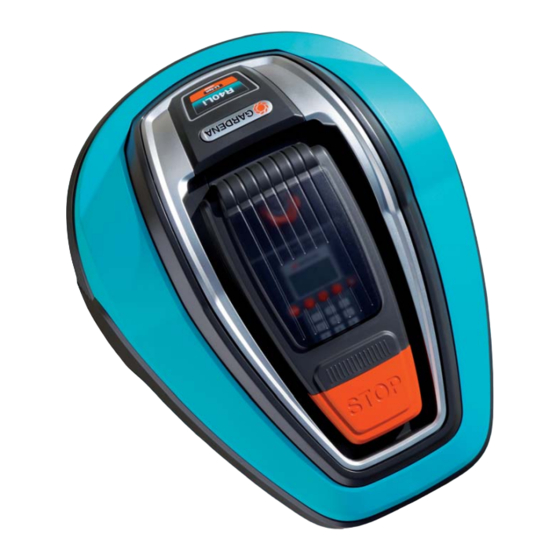
1. FUNCTION 1.2 GARDENA R40Li and R70Li, what is what? Start 3018-036 The numbers in the picture correspond to: Body 13. Charging strips Display cover, keyboard and cutting height 14. Keypad adjustment 15. Display Stop button/Catch to open the cover 16. -
Page 7: Introduction
1. FUNCTION 1.3 Introduction This Technical Manual contains important information about the Husqvarna Automower 305, 308 and ® GARDENA R40Li, R70Li robotic lawnmowers and their function, how to install them and a number of installation examples. It also contains information about... -
Page 8: Technical Data Husqvarna Automower
1. FUNCTION 1.4 Technical data Husqvarna Automower ® Table 1: Technical data Husqvarna Automower ® Data Dimensions Length 55 cm 55 cm Width 39 cm 39 cm Height 25 cm 25 cm Weight 6.4 kg 6.4 kg Electrical system Battery... -
Page 9: Technical Data Gardena
1. FUNCTION 1.5 Technical data Gardena Table 1: Technical data Gardena Data R40Li R70Li Dimensions Length 58 cm 58 cm Width 46 cm 46 cm Height 26 cm 26 cm Weight 7.4 kg 7.4 kg Electrical system Battery Specialised Lithium-Ion battery, Specialised Lithium-Ion battery, 18 V / 1.6 Ah 18 V/1.6 Ah... -
Page 10: Software
Quick Check and go to the main menu. It is important that the robotic lawnmower is programmed with the latest software versions. The Husqvarna Group is continuously improving the mower’s behaviour and performance, which results in new software versions. -
Page 11: Mowing Technique
Use only approved lawnmowers, the robotic lawnmower cuts the grass original blades from the Husqvarna Group. From the instead of knocking it off. start of 2011, these are marked with a Husqvarna or GARDENA symbol. 1.7.1 Mowing in different weather conditions 1.7.3 Irregular mowing pattern... -
Page 12: The Loop System's Control Signals
1. FUNCTION 1.8 The loop system’s control • Guide signal The signal that the charging station transmits signals through the guide wire. The guide signals The loop system consists of a boundary wire and lead the mower to the charging station, a guide wire connected to the charging station. -
Page 13: Boundary Wire
1. FUNCTION The strength of the A signal also varies along Table 2: Colours in the charging station’s LED the boundary wire depending on the proximity Colour Status to other parts of the loop. The strength of the Solid green light All signals are OK signal is affected by the size of the working area, islands, headlands, passages and corners. -
Page 14: Guide Wire
1. FUNCTION 1.11 Guide wire 1.12 Guide width The guide wire, together with the part of the boundary Guide width is a measure of how far from the guide wire that comprises the return to the charging station, wire the mower is allowed to travel when it is following is called the guide wire. -
Page 15: Searching Methods To Find The Charging Station
1. FUNCTION The default guide width setting for Automower 305, ® Guide 308 and Gardena R70Li is Medium. In general as wide a corridor as possible should be used. As well as reducing the risk of tracks forming, it also makes it easier for the robotic lawnmower to follow the guide 45˚... -
Page 16: Battery
1. FUNCTION 1.15 Battery 1.16 Sensors The robotic lawnmower is equipped with a Li-Ion There are several different types of sensor in the battery. Compared with a NiMH, for example, Li- mower. A collision sensor (1), tilt sensor (2) and lift Ion has very good properties, even at high ambient sensor (3) have the task of protecting both mower temperatures. -
Page 17: Special Menu Functions
2. SPECIAL MENU FUNCTIONS 2 Special menu functions 2.1 List, menu functions 2.2 Quick Check _____________________________________________16 2.3 Ascertain the PIN code ____________________________________18 2.4 Tools menu ______________________________________________18 2.5 305 main menu overview __________________________________19 2.6 R40Li main menu overview ________________________________20 2.7 Tools menu overview _____________________________________21 2.8 Tools menu, functions ____________________________________22 2.8.1 Info (5-1) ____________________________________________22 General (5-1-1) _______________________________________22... -
Page 18: Quick Check
2. SPECIAL MENU FUNCTIONS 2.2 Quick Check The display mode Battery shows: Quick Check is a display mode where you can quickly see information about program versions, Voltage: 20.1V battery, loop signals, sensors and operating history. No of chargings: Charge level: 1160 mAh When the start page or the main menu is displayed: Current:... - Page 19 2. SPECIAL MENU FUNCTIONS 2.2.2 History robotic lawnmower is directly over the loop, the value is 0 and when the mower is In display mode Messages the last 20 messages outside of the loop, the value is negative. can be read. The list of messages can also be •...
-
Page 20: Ascertain The Pin Code
2. SPECIAL MENU FUNCTIONS 2.3 Ascertain the PIN code 2.4 Tools menu If you forget the PIN code for the robotic lawnmower In addition to the main menu selections which are or when a mower is blocked because an incorrect described in the Operator’s Manual, there is a code has been entered, you can find out the right further one called Tools. -
Page 21: Main Menu 305, 308 And R70Li, An Overview
2. SPECIAL MENU FUNCTIONS 2.5 Main menu 305, 308 and R70Li, an overview English - 19... -
Page 22: R40Li Main Menu Overview
2. SPECIAL MENU FUNCTIONS 2.6 R40Li main menu overview English - 20... -
Page 23: Tools Menu Overview
2. SPECIAL MENU FUNCTIONS 2.7 Tools menu overview English - 21... -
Page 24: Tools Menu, Functions
2. SPECIAL MENU FUNCTIONS 2.8.1 Info (5-1) 2.8 Tools menu, functions The values displayed in this sub-menu show Via the Tools menu you can access data about the current status of the mower’s different sub- the mower’s function, test functions and special systems, e.g. -
Page 25: Loop (5-1-3)
2. SPECIAL MENU FUNCTIONS Battery (5-1-2) Sensors (5-1-4) The Battery sub-menu shows: The Loop sub-menu shows: • Voltage: The battery’s current voltage level. • Collision: One way of testing the collision A value of about 21V indicates a fully charged sensor is to hold the mower chassis by the battery and about 18V indicates a low battery. - Page 26 2. SPECIAL MENU FUNCTIONS 2.8.2 History (5-2) • Compl. chargings Counts number of complete chargings. You can use the values shown in this sub-menu to A complete charging is defined as a determine how well the mower has been working. charging that has proceeded for more than When a value deviates from the norm, this may be 20 minutes and that has been terminated as...
- Page 27 2. SPECIAL MENU FUNCTIONS 2.8.3 Test (5-3) NOTE ! If you have to help the wheel to go round by hand in order to get the wheel You can use this function to manually test how well motor started and if the wheel motor stops as the components in the robotic lawnmower work.
- Page 28 2. SPECIAL MENU FUNCTIONS 2.8.4 Special settings (5-4) User interface (5-3-2) The sub-menu consists of two part menus which giver access to specialised settings. Keypad (5-3-2-1) The display indicates which button is pressed down. Info Press Arrow back to exit the test. Loop signal History Display (5-3-2-2)
-
Page 29: Installation
3. INSTALLATION 3 Installation 3.1 Charging station The placement of the charging station should be min 1,5m min 2m well planned in order to give the best installation and operation of the robotic lawnmower. • The charging station should have a central position in the working area so that the 3020-012 robotic lawnmower is close to it from all... -
Page 30: Boundary Wire
3. INSTALLATION it rains if the joint between two cables is on • The charging station must not be positioned the ground. in a corner of the boundary loop. • It is recommended to use an earth-fault breaker when connecting the transformer to the wall socket. - Page 31 3. INSTALLATION Couplers The robotic lawnmower interprets an odd number of wires next to each other as an outer edge where it If the supplied boundary wire is not long enough has to turn. The mower will however run over an even to cover the entire working area, extra wire can be number of wires close to each other.
-
Page 32: Guide Wire
3. INSTALLATION 3.3 Guide wire If the guide wire must be laid in a passage: 3.3.1 Installation of the guide wire • Check that the charging station is in the best position. • The position of the charging station and where the guide wire is connected along the boundary wire has an impact on how long the guide loop will be, see “1.11 Guide wire”... -
Page 33: Testing The Installation
3. INSTALLATION 3.4 Testing the installation If the mower collides with any obstacle while it follows the guide wire via Remote start, it will This section does not apply to the GARDENA change direction and begin mowing. R40Li. Use a regular boundary wire as a guide wire. As a part of the installation, selected settings for the The guide wire must be connected to the boundary installation must be tested. -
Page 34: Testing The R40Li Installation
3. INSTALLATION Test the selected guide width Place the mower in the charging station and activate Test out (2-3-2) again to check that Place the mower in the charging station. the distance indicated is correct. Select the required Guide width (2-1). Indicate a distance in Remote start - IMPORTANT INFORMATION Distance (2-2-2) that definitely exceeds the... -
Page 35: Calibrate Guide
3. INSTALLATION 3.6 Calibrate guide To determine the signal strength at various distances from the guide wire in the actual installation, the robotic lawnmower performs a calibration in some situations. The calibration is performed automatically on the following occasions. • The first time a new robotic lawnmower leaves the charging station. -
Page 36: Even Mowing Results In Complex Working Areas
For regular use of a mower for several working • If the robotic lawnmower is travelling areas, one of the models from Husqvarna Group forward on a downhill slope and reaches a which do not require the generation of a new loop gradient of 50%, the same action is taken as signal is recommended. -
Page 37: Slope Conditions
Automower 305, 308 and GARDENA R40Li, R70Li ® in any way, which the PIN code in Husqvarna G2 delivers a very good mowing result when it is installed models does. correctly and in a working area for which the mower is intended. -
Page 38: Installation Examples
3. INSTALLATION 3.13 Installation examples The following pages contain a number of examples of installations. The aim of these examples is to demonstrate how quickly it is possible to get started with the robotic lawnmower’s basic settings and get a good installation. However, the examples also show that good planning and correctly selected settings can turn a satisfactory installation into a very good one. - Page 39 3. INSTALLATION 3.13.1 Example 1 This mower installation works well without having to change its factory settings. The mower will be able to navigate through the passage and access the entire working area. The passage width does not allow one to use the Guide width Wide setting in Automower 305, 308 and GARDENA R70Li.
- Page 40 3. INSTALLATION 3.13.2 Example 2 For Automower 305, 308 and GARDENA R70Li, this installation is not approved with the factory settings. ® The passage is too narrow for Guide width Medium which means that the mower will not be able to follow the guide through the passage and thus not find its way back to the charging station from area 2.
- Page 41 3. INSTALLATION 3.13.3 Example 3 The installation in the picture on the left below is not approved due to the position of charging station. The charging station is positioned too close to the boundary wire on the right side (viewed in the direction towards the charging station), which can affect the Guide signal.
- Page 42 3. INSTALLATION 3.13.4 Example 4 With Automower 305, 308 and GARDENA R70Li, there is a risk Area 1 will not be mown enough using the ® factory settings. Because Area 1 is just over half of the working area, Remote Start - Proportion has to be increased to ensure an even mowing result.
- Page 43 3. INSTALLATION 3.13.5 Example 5 In this installation there is a risk of tracks forming alongside the guide wire as the bulk of the working area is accessed via a narrow passage, thus requiring that Remote start - Proportion be set to Often. The mowing time is also reduced as the robotic lawnmower does not mow when it follows the guide wire.
-
Page 44: Autocheck Exp Service Program
The Autocheck EXP service program is a tool to use in connection with service of robotic lawnmowers 4.1.2 Log in to Autocheck EXP from the Husqvarna Group. Its uses include: Start the program by double clicking on the • Updating software in the robotic lawnmower program icon on the desktop. -
Page 45: Connection To The Robotic Lawnmower
4. AUTOCHECK EXP SERVICE PROGRAM 4.2 Connection to the robotic lawnmower Connect the service cable between your computer and the robotic lawnmower: • Remove the protective cover for the battery on the bottom of the mower. The service outlet is located under the cover, beside the battery. -
Page 46: Use
4. AUTOCHECK EXP SERVICE PROGRAM 4.3 Use Autocheck EXP has been designed to be as self-instructional as possible. There are a lot of help texts and illustrations in the program to guide the user. The program’s main functions are grouped in a number of menus that are accessed via buttons in a list in the upper part of the program. - Page 47 4. AUTOCHECK EXP SERVICE PROGRAM 4.3.1 Auto test In Auto test, a comprehensive test of the components in the robotic lawnmower is carried out. The test is semi- automatic, which means each component is started and stopped by the service program. Auto test is a suitable function to use for an overall review of the components, for example, in connection with winter service or to start troubleshooting.
- Page 48 4. AUTOCHECK EXP SERVICE PROGRAM 4.3.2 Manual test Fault memory This list displays the last 50 faults to occur. The Every component in the robotic lawnmower can be fault is displayed with the date and time and where tested in the manual test. The function consists of the last fault to occur is shown at the top of the four parts: list.
- Page 49 4. AUTOCHECK EXP SERVICE PROGRAM Programming new main circuit board If the main circuit board is replaced, the new main circuit board must be programmed. The main circuit board includes for instance information about the robotic lawnmower’s serial number. A new main circuit board may for safety reasons be only assigned one serial number which is never changed.
- Page 50 4. AUTOCHECK EXP SERVICE PROGRAM 4.3.5 Logbook 4.3.7 The Assistant Logbook is used to simply save information about The Assistant is found in the program’s bottom a large number of mowers in a database. The corner. It provides information about the status of information can then be searched and used even both Autocheck EXP and the mower connected.
- Page 51 There is a complete collection of documents for robotic lawnmowers from the Husqvarna Group, with models from 2003 and later. Current service plans for many mower models are also here. Documents marked in red are newly added and unopened documents.
-
Page 52: Repair Instructions
5. REPAIR INSTRUCTIONS 5 Repair Instructions 5.1 Design and Function All repairs to robotic lawnmowers should be done 5.1.1 Chassis and body indoors on a clean work bench to protect sensitive components from moisture and dirt. The robotic lawnmower is mechanically built using the following major components: •... - Page 53 5. REPAIR INSTRUCTIONS 5.1.2 Circuit boards 5.1.3 Sensors There are three circuit boards in the robotic The robotic lawnmower is equipped with the following lawnmower: sensors: • Main circuit board (1) • Collision sensor (1) • MMI circuit board (2) •...
- Page 54 Use only an original battery from the Husqvarna Group. The battery must not be mixed up with similar batteries used for instance with other GARDENA lawn care products.
-
Page 55: Wheel Motors (5-1-5)
5. REPAIR INSTRUCTIONS 3020-024 3020-026 5.1.7 Blade motor 5.1.9 Charging station The blade motor is a highly effective brushless Automower 305,308 and GARDENA R40Li, ® motor of the three-phase type. The nominal rotation R70Li are charged with direct current (in contrast speed for optimum mowing results is 2,900 rpm. -
Page 56: Disassembling And Assembling The Robotic Lawnmower
5. REPAIR INSTRUCTIONS 5.2 Disassembling and assembling the robotic lawnmower IMPORTANT INFORMATION Clean any grass and dirt from the robotic lawnmower before you begin disassembling. 3020-029 5.2.1 Disassembling the body 5.2.3 Disassembling the chassis The body is screwed to the chassis with four screws. - Page 57 5. REPAIR INSTRUCTIONS 5.2.4 Assembling the chassis, display cover and body IMPORTANT INFORMATION When assembling: Make sure parts are clean and that no cables will be pinched. An unsealed chassis can let in moisture, 3020-033 which can result in faults in the mower. Screw the upper and lower parts of the Always use new sealing strips before chassis together with the 10 screws...
-
Page 58: Disassembling The Charging Station
5. REPAIR INSTRUCTIONS 5.3 Disassembling the charging Fit the display cover on the chassis. Check that neither the MMI cable nor the buzzer station cable are pinched between chassis and display cover. When assembling it is Replacing the wiring in the charging station important to first feed as much as possible requires the charging station to be completely of the cables down into the chassis and... -
Page 59: Assembling The Charging Station
5. REPAIR INSTRUCTIONS Replace the circuit board. Insert the card in the correct slot in the charging station, fit the circuit board holders in place and secure them with screws (Torx 20). The circuit board for R40Li and R70Li must be mounted in the rear slot and for 305 and 308 in the front slot, seen facing the charging station. -
Page 60: Replacing Charging Strips
Fit a new original battery from the charging strips in the rear wheel bracket. Husqvarna Group. NOTE! Note the position for the red and NOTE! Press on the connector to fit the black cables respectively to ensure that battery in place. -
Page 61: Replacing The Main Circuit Board
5. REPAIR INSTRUCTIONS Fit the battery cover. The sealing strip is Select the correct serial number in the reusable and does not need to be replaced. logbook. Autocheck EXP now automatically transfers the operating information saved in Tighten the four screws for the battery step 1. -
Page 62: Replacing The Keypad
5. REPAIR INSTRUCTIONS 3020-046 Remove the MMI circuit board. IMPORTANT INFORMATION 3020-047 Remove the protective film from the new Only touch the edges of the circuit keypad and then press it onto the display board. Never touch the card’s cover. Remember to thread the cable components and pin terminals. -
Page 63: Replacing The Buzzer
5. REPAIR INSTRUCTIONS 5.14 Replacing the main switch Clean the filter carefully with a clean and soft brush. Disassemble the body, display cover and If damaged, the filter must be changed. chassis. See “5.2 Disassembling and To change the filter: assembling the robotic lawnmower”... -
Page 64: Replacing The Husqvarna Microswitch
5. REPAIR INSTRUCTIONS 5.15 Replacing the Husqvarna microswitch Disassemble the body. See “5.2.1 Disassembling the body” on page 54. Remove the display cover. See “5.2.2 Disassembling the display cover” on page 54. Turn the display cover upside down. Place the mower on a soft and clean surface to 3020-050 avoid scratching the body. -
Page 65: Replacing The Sensors
5. REPAIR INSTRUCTIONS 5.17 Replacing the sensors 5.17.2 Collision sensor, tilt sensor and rear loop sensor The rear loop sensor, collision sensor and tilt sensor 5.17.1 Lift sensor and Front loop sensor are parts of the main circuit board. The sensors cannot The front loop sensor and lift sensor are mounted be replaced separately. -
Page 66: Replacing The Wheel Motor
5. REPAIR INSTRUCTIONS Remove the hub cap on the drive wheel. The hub cap is secured by means of three snap fasteners that are accessed from the inside of the drive wheel. 3020-052 16. Simultaneously assemble the blade motor housing and the screws that adjust the cutting height in the chassis’... -
Page 67: Replacing The Rear Wheel Bearings
To further improve protection of the bearings and reduce the risk of noise between the seals and the shaft, it is recommended to apply grease to the shaft before the seals are fitted. Use Husqvarna Automower chassis grease. ®... -
Page 68: Replacing The Husqvarna Front Rubber Dampers
5. REPAIR INSTRUCTIONS 5.22 Replacing the Husqvarna 5.23 Replacing the GARDENA front front rubber dampers rubber dampers Disassemble the body. See “5.2.1 NOTE! When disassembling the body’s components, it is normal that the GARDENA plate is damaged and Disassembling the body” on page 54. -
Page 69: Mounting Screws
5. REPAIR INSTRUCTIONS 5.24 Mounting Screws 5.25 Mounting thread plugs It is extremely important how screws are mounted If the threads in plastic parts are worn, thread in plastic. If the screws are mounted incorrectly, plugs can be inserted. A repair kit containing there is a risk of damaging the threads in the plastic thread plugs and suitable metal screws is and thereby shortening the service life of the plastic... -
Page 70: Screw Fasteners
5. REPAIR INSTRUCTIONS 5.26 Screw fasteners All screws are made from stainless material or rustproofed with zinc plating. Article numbers are to be found in the separate Spare Parts List. Table 6: Screw fasteners Fastener Hardware Tool Total Tightening Remark torque (Nm) Chassis, lower section Battery cover... - Page 71 5. REPAIR INSTRUCTIONS Body Front bumper Screw Torx 20 0.7 - 1.0 Not for R40Li/ R70Li 4 x 14 mm Front collision column Screw Torx 25 1.0 - 1.5 M5 x 12 mm Rear collision column Screw Torx 20 0.7 - 1.0 holder 4 x 14 mm Rear collision column...
-
Page 72: Troubleshooting
5. REPAIR INSTRUCTIONS 6 Troubleshooting The troubleshooting section consists of two main areas; Messages Symptoms Each message and symptom is explained using one or more possible causes of the problem, followed by one or more solutions. First go through the basic and installation-related possible causes described in the following sections in this chapter. -
Page 73: Messages
See “5.8 Replacing the battery” on page 58. Wrong type of battery Use only original batteries from the Husqvarna Group. Temporary battery Wrong type of battery. Use only original batteries from the problem Husqvarna Group. - Page 74 6. TROUBLESHOOTING 22/23 Wheel motor The wheel motor is defective Check the wheel motors’ function problem, right/le when idling. See “Motors (5-3-1)” on page 25. The main circuit board is Replace the main circuit board. See defective “5.9 Replacing the main circuit board” on page 59.
- Page 75 6. TROUBLESHOOTING Outside working The boundary wire Check that the boundary wire is area connections to the charging connected correctly. See Connecting station are crossed. the boundary wire in the Operator’s Manual. The working area slopes too Check that the boundary wire much at the boundary wire.
- Page 76 See “5.21 Replacing the rear rubber dampers” on page 65 and “5.22 Replacing the Husqvarna front rubber dampers” on page 66 or “5.23 Replacing the GARDENA front rubber dampers” on page 66.
- Page 77 Thus, one cannot, for instance use an MMI circuit board in a Husqvarna 305 if it has previously been fitted to a GARDENA R40Li. English - 75...
- Page 78 6. TROUBLESHOOTING Settings restored User settings failed to save If the fault occurs repeatedly, program and the mower has been the mower with the most recent main reset to factory settings. program. See “4.3.4 Programming” on page 46. If the fault occurs repeatedly, even using the most recent main program, replace the main circuit board.
-
Page 79: Symptoms
6. TROUBLESHOOTING 6.2 Symptoms The most commonly occurring symptoms are described below. All symptoms are grouped according to the situation where they most frequently occur. Mowing Searching Following the guide wire Docking Charging Other 6.2.1 Symptoms during mowing Table 8: Symptoms during mowing Symptom Cause Action... - Page 80 6. TROUBLESHOOTING The robotic The wheel motor’s gearbox is Check the wheel motors’ function lawnmower travels in slipping. when idling via the Tools menu or use a small circle or one Autocheck EXP. The battery voltage wheel locks up when should be more than 18 V in this test.
- Page 81 6. TROUBLESHOOTING 6.2.3 Symptoms during remote start Table 10: Symptoms during remote start Symptom Cause Action The robotic The guide width is too high for Reduce the guide width until the robotic lawnmower cannot the robotic lawnmower to get lawnmower is able to get through the passage. get through a through the passage.
- Page 82 6. TROUBLESHOOTING 6.2.4 Symptoms during docking Table 11: Symptoms during docking Symptom Cause Action The robotic The guide wire is incorrectly Check that the guide wire is placed correctly lawnmower detects positioned in the charging in its groove on the underside of the charging the guide wire and station.
- Page 83 6. TROUBLESHOOTING The mower HOME-mode is activated. Press the HOME button down and select Auto never leaves the or MAN. charging station TIMER settings are preventing Check the TIMER settings. the mower from leaving the charging station. The mower never becomes Check that the mower is receiving the charging fully charged.
- Page 84 6. TROUBLESHOOTING The display Defective microswitch Check the functioning of the microswitch and background lighting (for STOP button) and/or the keypad. Replace defective parts. is on but pressing defective keypad. the keyboard does not produce a reaction Using Test in The mower does not have a Place the mower in the charging station and run (2-3-1), the mower...
-
Page 85: Loop Signal Strength
6. TROUBLESHOOTING 6.4 Troubleshooting loop signal 6.3 Loop signal strength Always start by checking the LED in the charging When measuring loop signal strength the mower station. This usually provides a good indication of should be placed in the charging station. Use menu where troubleshooting should begin. - Page 86 6. TROUBLESHOOTING 6.4.2 Green flash • Value <20 Ohm: Indicates that the loop is intact. Check instead the connections to the ECO mode is enabled in the mower and no charging station. Replace the circuit board in loop signals are at present being transmitted in the charging station if the fault remains, see “5.5 the loop wires.
-
Page 87: Finding A Break In The Boundary Wire
LED still flashes blues, the fault is in the charging station’s cabling or the A wire break can be found by using Husqvarna’s circuit board. See “5.5 Replacing the circuit break detection tool or with the manual method that board, charging station”... - Page 88 If that is the case, cut away. Use only original couplers from move the connection for the new wire closer the Husqvarna Group. to the disconnected end (approximately in the middle of the suspected stretch) and check again whether the LED has turned green.
-
Page 89: Battery Test
6. TROUBLESHOOTING 6.6 Battery test is dead and needs to be replaced. Note that the values are approximate and vary between different If the mower’s battery starts to perform poorly, mowers and assume that the measuring is done the robotic lawnmower will mow for shorter time as described. -
Page 90: Maintenance And Service
6. TROUBLESHOOTING 7 Maintenance and 7.2 Winter storage service Before the robotic lawnmower is put away for the winter, the following should be done: • Clean the entire mower thoroughly. • Remove the blade disc and clean around 7.1 Cleaning the blades so that they can be freely rotated and also around the motor shaft. -
Page 91: Service Plan
Make sure there are no cracks and that the rubber dampers are not deformed. Refer to ”5.20 Replacing the rear wheel bearings” and ”5.22 Replacing the Husqvarna front rubber dampers” or ”5.23 Replacing the GARDENA front rubber dampers”. Check mobility and condition of both Make sure the collision columns can move front lifting columns. -
Page 92: Restore User Settings
7. MAINTENANCE AND SERVICE Clean the inner space's charging Refer to ”5.7 Replacing charging strips” for plate and apply more grease to the dismantling the rear wheel bracket. Apply contact pins. grease to the cable lugs. 3020-042 Clean the charging station. Inspect and polish charging plates on Polish contact surfaces on both mower and mower and in charging station. - Page 94 ® AUTOMOWER is a trademark owned by Husqvarna AB. Copyright © 2014 HUSQVARNA. All rights reserved. 115 67 75-26...