
Related Manuals for Siemens HT-direct


Summary of Contents for Siemens HT-direct
- Page 1 Three-phase synchronous motor HT-direct Type 1FW4 Operating Instructions • 01/2009 ht-direct...
- Page 2 14.01.2009 16:26...
- Page 3 Safety information Description, technical data Transport, installation and assembly Commissioning Three-phase synchronous motor Operation HT-direct Maintenance 1FW4 Disposal and recycling Operating Instructions Replacement parts Edition 01/2009...
- Page 4 Note the following: WARNING Siemens products may only be used for the applications described in the catalog and in the relevant technical documentation. If products and components from other manufacturers are used, these must be recommended or approved by Siemens. Proper transport, storage, installation, assembly, commissioning, operation and maintenance are required to ensure that the products operate safely and without any problems.
-
Page 5: Table Of Contents
Connecting the ground conductor....................48 3.10 Connection of the machine ......................50 3.11 Instructions for terminal box type 1XB1 631 ................55 3.12 Connecting the anti-condensation heating and auxiliary circuits..........56 3.13 Connection of the external fan motor...................57 A5E01083943A AB Siemens AG Operating Instructions 2.02 1FW4... - Page 6 Replacement parts........................... 91 Orders for spare parts ......................... 91 Information on the anti-condensation heating................91 Stators and rotors for water-cooled 1FW4 motors ..............92 Stators and rotors for air-cooled 1FW4 motors................93 A5E01083943A AB Siemens AG Operating Instructions 2.02 1FW4...
- Page 7 Stator and rotor ..........................93 Table 8-3 Bearing bush DE..........................94 Table 8-4 Bearing bush NDE ........................95 Table 8-5 External fan ..........................96 Table 8-6 Pulse encoder ..........................97 Table 8-7 Spare parts list for terminal box 1XB1631 ...................98 A5E01083943A AB Siemens AG Operating Instructions 2.02 1FW4...
- Page 8 Figure 8-3 Bearing bush DE ......................... 94 Figure 8-4 Bearing bush NDE ........................95 Figure 8-5 Mounted external fan ........................96 Figure 8-6 Pulse encoder ..........................97 Figure 8-7 Terminal box 1XB1631........................ 98 A5E01083943A AB Siemens AG Operating Instructions 2.02 1FW4...
-
Page 9: Safety Information
1. Isolate 2. Protect against reconnection 3. Make sure that the equipment is de-energized 4. Ground and short-circuit 5. Cover or enclose adjacent components which are still live [ID 800.01] A5E01083943A AB Siemens AG Operating Instructions 2.02 1FW4... -
Page 10: Safety And Application Instructions
These instructions therefore only contain the information which is necessary for the motors to be used by qualified persons in accordance with their intended purpose. Note We recommend engaging the support and services of your local Siemens service center for all planning, installation, commissioning and maintenance work. [ID 2.01]... -
Page 11: Magnetic Fields Of 1Fw4 Motors
The permanent magnet rotor may only be removed by the manufacturer and the bearing may only be replaced by certified service partners. Should on-site removal of the magnetic rotor or a bearing change prove necessary, please contact the Siemens Service Center. WARNING Effect of strong magnetic fields on personnel Strong magnetic fields can directly affect persons and cause damage. - Page 12 Magnetic fields can cause loss of data on magnetic or electronic data media. Do not carry any magnetic or electronic data media with you! [ID 1146.00] See also SIEMENS Service Center (Page 23) A5E01083943A AB Siemens AG Operating Instructions 2.02 1FW4...
-
Page 13: Ec Declaration By The Manufacturer
Safety information 1.5 EC Declaration by the Manufacturer EC Declaration by the Manufacturer A5E01083943A AB Siemens AG Operating Instructions 2.02 1FW4... - Page 14 Safety information 1.5 EC Declaration by the Manufacturer A5E01083943A AB Siemens AG Operating Instructions 2.02 1FW4...
- Page 15 Safety information 1.5 EC Declaration by the Manufacturer A5E01083943A AB Siemens AG Operating Instructions 2.02 1FW4...
- Page 16 Safety information 1.5 EC Declaration by the Manufacturer A5E01083943A AB Siemens AG Operating Instructions 2.02 1FW4...
- Page 17 Safety information 1.5 EC Declaration by the Manufacturer A5E01083943A AB Siemens AG Operating Instructions 2.02 1FW4...
-
Page 18: Eu Declaration Of Conformity 73/23/Eec
Safety information 1.6 EU Declaration of Conformity 73/23/EEC EU Declaration of Conformity 73/23/EEC A5E01083943A AB Siemens AG Operating Instructions 2.02 1FW4... - Page 19 Safety information 1.6 EU Declaration of Conformity 73/23/EEC A5E01083943A AB Siemens AG Operating Instructions 2.02 1FW4...
- Page 20 Safety information 1.6 EU Declaration of Conformity 73/23/EEC A5E01083943A AB Siemens AG Operating Instructions 2.02 1FW4...
- Page 21 Safety information 1.6 EU Declaration of Conformity 73/23/EEC A5E01083943A AB Siemens AG Operating Instructions 2.02 1FW4...
- Page 22 Safety information 1.6 EU Declaration of Conformity 73/23/EEC A5E01083943A AB Siemens AG Operating Instructions 2.02 1FW4...
- Page 23 Safety information 1.6 EU Declaration of Conformity 73/23/EEC A5E01083943A AB Siemens AG Operating Instructions 2.02 1FW4...
-
Page 25: Description, Technical Data
Details regarding the design of this electrical machine and the permissible operating conditions are described in these Operating Instructions. If you have any questions or suggestions, or if you require additional information, please contact the Siemens Service Center: Table 2-1... -
Page 26: Figure 2-1 1Fw4 Water-Cooled Motor
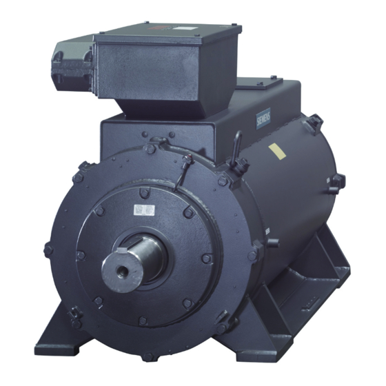
If you connect the motor directly to the electrical power supply it may be destroyed. The motor may only be operated with a frequency converter. Figure 2-1 1FW4 water-cooled motor Figure 2-2 1FW4 air-cooled motor [ID 1147.00] A5E01083943A AB Siemens AG Operating Instructions 2.02 1FW4... -
Page 27: Converter Assignment
1FW4-motors. The selection of the converter module depends on many influencing factors, e.g., torque, speed, overload, load cycles, control precision, regenerative capability, etc. You can find more detailed information in Catalog "HT-direct 1FW4". For more complex questions, contact your Siemens sales representative. CAUTION... -
Page 28: 1Fw4 Water-Cooled Version Rating Plate
The data regarding the actual degree of protection, cooling, and the construction type should be taken from the rating plate. [ID 1129.00] 1FW4 water-cooled version rating plate rating plate SIEMENS Figure 2-3 Rating plate for water-cooled 1FW4 motors A5E01083943A AB Siemens AG Operating Instructions 2.02 1FW4... -
Page 29: 1Fw4 Air-Cooled Version Rating Plate
[°C] Power factor (19) Maximum water pressure [bar] (10) Motor weight [t] [ID 804.02] 1FW4 air-cooled version rating plate rating plate SIEMENS Figure 2-4 Rating plate for air-cooled 1FW4 motors A5E01083943A AB Siemens AG Operating Instructions 2.02 1FW4... -
Page 30: Table 2-4 Rating Plate Data
Rotors, standards and regulations Temperature class (14) Rated output [kW] Degree of protection (15) Rated current [A] Rated torque [Nm] (16) Rated frequency [Hz] Rated speed [1/min] (17) Rated voltage [V] Power factor [ID 1131.00] A5E01083943A AB Siemens AG Operating Instructions 2.02 1FW4... -
Page 31: Definitions Of The Electrical Data
Damage to the insulation Continuous duty above the S1 characteristic is not thermally permitted for the motor. The insulation can get damaged. - Also see Figure "Rotation-to-speed characteristic of the synchronous motors". A5E01083943A AB Siemens AG Operating Instructions 2.02 1FW4... - Page 32 This current limit is only determined by the magnetic circuit. Even if this is briefly exceeded, it can result in irreversible de-magnetization of the magnetic material. Maximum speed n The maximum permissible speed is n A5E01083943A AB Siemens AG Operating Instructions 2.02 1FW4...
- Page 33 (step increase) up to the permissible S1 torque. The motor has reached 63% of its final temperature after T A5E01083943A AB Siemens AG Operating Instructions 2.02 1FW4...
-
Page 34: Technical Design
Water-cooling (Page 34) Air cooling (Page 37) Technical design Technical data Table 2-6 Technical data of the standard version Features Design/values Type of motor Permanent-magnet synchronous motor Magnet material Rare-earth magnet material A5E01083943A AB Siemens AG Operating Instructions 2.02 1FW4... - Page 35 1) The specified values only refer to the motor. These values can be increased at the motor due to the overall vibration characteristics of the complete system after the drive has been mounted. 2) At temperatures below 0°C, anti-freeze is required for water-cooled motors. [ID 1149.00] A5E01083943A AB Siemens AG Operating Instructions 2.02 1FW4...
-
Page 36: Cooling
To prevent the formation of condensation water, the coolant supply temperature for a stationary motor and still running cooling system must be higher than the ambient temperature. ≥ T +2°C cooling ambient A5E01083943A AB Siemens AG Operating Instructions 2.02 1FW4... -
Page 37: Table 2-7 Derating Factors Depending On The Coolant Supply Temperature And The Ambient
Table 2-9 Chemical requirements of the water quality Contents and chemical composition Value pH value 6.0 to 8.0 pH Total hardness < 170 ppm Chloride < 40 ppm Sulphate < 50 ppm A5E01083943A AB Siemens AG Operating Instructions 2.02 1FW4... -
Page 38: Figure 2-6 Example Of A Cooling Circuit
The recooling unit is not part of the motor's scope of delivery. Filter Temperature-sensing coolant Throughput quantity display Compressor/recooling unit Flow regulating valve Motor Pump Recooling unit Cooling-medium reservoir 1) These components are not absolutely necessary. Figure 2-6 Example of a cooling circuit A5E01083943A AB Siemens AG Operating Instructions 2.02 1FW4... -
Page 39: Air Cooling
O. R. O. R. O. R. O. R. O. R. O. R. O. R. The ambient temperature is rounded up to 5°C. The site altitude is rounded up to 500 m. [ID 1140.00] A5E01083943A AB Siemens AG Operating Instructions 2.02 1FW4... -
Page 41: Transport, Installation And Assembly
Covers or tarpaulins used to protect the equipment against the weather must not make contact with the surfaces of the equipment. Place wooden spacer blocks between the covers and the motor. This ensures sufficient air circulation. A5E01083943A AB Siemens AG Operating Instructions 2.02 1FW4... -
Page 42: Protection Of The Cooling Water Ducts For The Water-Cooled Version
If the cooling water has been removed, you must flush the cooling circuit with an anti- corrosive agent if the motor is going to sit idle for a long period of time. A5E01083943A AB Siemens AG Operating Instructions 2.02 1FW4... -
Page 43: Installation
• Unable to come into contact with any rotating parts Observe the technical data in these operating instructions and on the rating plate! If any transport locks are in place, remove them before installation. A5E01083943A AB Siemens AG Operating Instructions 2.02 1FW4... - Page 44 Depending on the ambient conditions, it might make sense to remove the plastic plugs. NOTICE Reducing the degree of protection Nominally, the degree of protection of the motor is reduced to IP44 by removal of the plastic plug. A5E01083943A AB Siemens AG Operating Instructions 2.02 1FW4...
-
Page 45: Aligning
Rolling-contact bearings The permissible values for the longitudinal and transverse forces can be found in the catalog and can be obtained from your local Siemens sales office if required. The 1FW4 motor may only be operated using a flexible coupling. -
Page 46: Table 3-1 Permissible Deviations
Permissible deviation for Radial shaft offset [e] Axial shaft offset [Δh] Rigid coupling 0.03 mm 0.02 mm Flexible coupling 0.05 mm 0.05 mm [ID 845.01] See also SIEMENS Service Center (Page 23) A5E01083943A AB Siemens AG Operating Instructions 2.02 1FW4... -
Page 47: Mounting
Also consider the pressure load and compatibility with the materials from which the cooler is made. 2. Route and support the water pipes so that the connecting flanges are not exposed to excessive stress or strain or vibration loads. A5E01083943A AB Siemens AG Operating Instructions 2.02 1FW4... -
Page 48: Connection To The Converter
With each rotation of the rotor, a voltage occurs at the motor terminals. As a result of this, there is also a voltage at the converter output terminals via the connecting cable. When working on the drive system, you must prevent any rotational movement of the motor shaft. A5E01083943A AB Siemens AG Operating Instructions 2.02 1FW4... -
Page 49: Figure 3-2 Cable With Symmetrical Cable Cross-Section
Cable with symmetrical cable cross-section ● To ensure good discharging of high-frequency currents, provide contacting over a large surface area. Establish a 360° contact of the cable shielding on the motor housing and on A5E01083943A AB Siemens AG Operating Instructions 2.02 1FW4... -
Page 50: Connecting The Ground Conductor
– Use a separate RF equipotential bonding cable between the motor housing and the protective grounding bar of the converter ● Use the common-mode filter (damping cores) at the converter output. The Siemens sales representative is responsible for selection and dimensioning. -
Page 51: Table 3-2 Tightening Torques Of Bolts (Cable Lug)
In the terminal box, use the connection terminals designated for the ground conductor. Connecting the radio-frequency ground for forced-ventilated motors Note For water-cooled motors, a radio-frequency ground is required between the terminal box and the housing due to the steel housing. A5E01083943A AB Siemens AG Operating Instructions 2.02 1FW4... -
Page 52: Connection Of The Machine
Select the connecting cables in accordance with DIN VDE 0100 and in accordance with the rated current and the installation-specific conditions (e.g. ambient temperature, routing method etc. according to DIN VDE 0298 or IEC/EN 60204-1). The necessary connection data regarding A5E01083943A AB Siemens AG Operating Instructions 2.02 1FW4... -
Page 53: Figure 3-4 Connection Of The Power Cable In The Main Terminal Box
(6 to 9 mm). When the length is correct, the conductor should reach the stop in the terminal and at the same time the conductor insulation should reach the contact part of the terminal. A5E01083943A AB Siemens AG Operating Instructions 2.02 1FW4... -
Page 54: Table 3-4 Terminal Designations (With The 1U1-1 As An Example)
Index showing the start (1) / end (2) or tapping point of the winding (if there is more than one connection per winding) Additional index for cases in which it is obligatory to connect parallel power feed cables to several terminals with otherwise identical designations A5E01083943A AB Siemens AG Operating Instructions 2.02 1FW4... - Page 55 This temperature effect can be reduced by altering the conditions at the entry points or by using modified cable entry plates after consultation with the manufacturing plant. A5E01083943A AB Siemens AG Operating Instructions 2.02 1FW4...
-
Page 56: Figure 3-6 Strain Relief Device And Sealing Insert
5 Nm (see illustration). On cables without secured routing, cable entries should be used with a strain relief device which is protected against twisting (e.g. similar to DIN 22419). A5E01083943A AB Siemens AG Operating Instructions 2.02 1FW4... -
Page 57: Instructions For Terminal Box Type 1Xb1 631
The cable entry gland must be aligned in relation to the terminal box housing such that the contact surface for the gasket in the terminal box cover is flat. This is the only way in which a perfect seal can be obtained. [ID 165] A5E01083943A AB Siemens AG Operating Instructions 2.02 1FW4... -
Page 58: Connecting The Anti-Condensation Heating And Auxiliary Circuits
● the connecting cables are laid in an open arrangement, and the cable insulation cannot be damaged. A5E01083943A AB Siemens AG Operating Instructions 2.02 1FW4... -
Page 59: Connection Of The External Fan Motor
● Then establish the other electrical connections as per the circuit diagram. ● If the fan is supplied with a connector already attached, then you must check whether the pin allocation of the connector matches the pin allocation of the socket. [ID 1157.00] A5E01083943A AB Siemens AG Operating Instructions 2.02 1FW4... -
Page 61: Commissioning
During a short circuit of a cable or converter, a short-circuit current is driven by the induced voltage which is present at the motor terminals due to the rotation of the permanent magnet rotors. [ID 817.01] A5E01083943A AB Siemens AG Operating Instructions 2.02 1FW4... -
Page 62: Danger And Warning Notices
If the supply feeder cables are connected, you must ensure that the line voltage cannot be connected. Once you have measured the insulation resistance, discharge the winding by connecting the ground potential. A5E01083943A AB Siemens AG Operating Instructions 2.02 1FW4... -
Page 63: Table 4-1 Insulation Resistance At 25°C
500 V 500 V Minimum insulation resistance with 10 MΩ 100 MΩ new, cleaned or repaired windings Critical specific insulation 0.5 MΩ/kV 5 MΩ/kV resistance after long operating period Note the following points: A5E01083943A AB Siemens AG Operating Instructions 2.02 1FW4... -
Page 64: Measures To Be Performed Prior To Start-Up
● the operating conditions are in accordance with the data specified on the nameplate. ● the bearings have been regreased (depending on model). Rolling-contact bearing motors which have been in storage for more than 2 years must be regreased. A5E01083943A AB Siemens AG Operating Instructions 2.02 1FW4... - Page 65 This is done by limiting the field weakening operation to 120%. Note This list does not claim to be exhaustive. It may be necessary to make additional checks and tests corresponding to the actual plant/system situation. [ID 828.01] A5E01083943A AB Siemens AG Operating Instructions 2.02 1FW4...
-
Page 66: Commissioning Of The Separate Fan
1,500 V (peak-to-peak). If higher voltages occur, change the configuration of the system, e.g., cable lengths and grounding concept, in such a manner that these voltages are not exceeded during operation. [ID 819.01] A5E01083943A AB Siemens AG Operating Instructions 2.02 1FW4... -
Page 67: Switching On
You must not switch on the anti-condensation heating until at least one hour after the motor has been switched off. This prevents damage to the winding insulation. [ID 965.01] A5E01083943A AB Siemens AG Operating Instructions 2.02 1FW4... -
Page 68: Switching Off Air-Cooled Motors
You must not switch on the anti-condensation heating until at least one hour after the motor has been switched off. This prevents damage to the winding insulation. [ID 618.02] A5E01083943A AB Siemens AG Operating Instructions 2.02 1FW4... -
Page 69: Operation
Cleaning To ensure proper functioning of the motor cooling system, the cooling circuits must be free of dirt, e.g., the grilles, ducts, ribs and pipes. A5E01083943A AB Siemens AG Operating Instructions 2.02 1FW4... -
Page 70: Stoppages
In the event that electrical faults occur during the operation of the motor with a converter, please also refer to the operating instructions of the frequency converter. The tables below list general faults caused by mechanical and electrical influences. A5E01083943A AB Siemens AG Operating Instructions 2.02 1FW4... -
Page 71: Table 5-1 Fault Table, Electrical Causes
Balance the coupled motor Coupled motor knocking Check coupled motor Resonance of the overall system comprising motor and After consultation, reinforce foundations foundation Changes in foundation Determine cause of changes, eliminate if necessary; realign motor A5E01083943A AB Siemens AG Operating Instructions 2.02 1FW4... - Page 72 (1) Apart from eliminating the cause of the fault (as described under "Remedial measures"), you must also rectify any damage the motor may have suffered. 2) Take any changes into account for heating up. [ID 829.01] A5E01083943A AB Siemens AG Operating Instructions 2.02 1FW4...
-
Page 73: Maintenance
When changing the bearings, you must avoid passing metallic objects through the rotor field into the motor. Should an on-site bearing change prove necessary, please contact the Siemens Service Center. DANGER Strong magnetic fields can directly affect persons and cause damage. -
Page 74: Preparations For Maintenance
Cleaning with compressed air When cleaning with compressed air, ensure there is an adequate exhaust system and observe personnel protection measures. For example, wear protective eyewear, a breathing filter or something similar! A5E01083943A AB Siemens AG Operating Instructions 2.02 1FW4... -
Page 75: Regreasing Intervals For Rolling-Contact Bearings, Grease Type
2. Apply a portion of an appropriate type of grease in the amount specified on the lubricant plate. The shaft must rotate so that the new grease can be distributed throughout the A5E01083943A AB Siemens AG Operating Instructions 2.02 1FW4... -
Page 76: Servicing The External Fan
The rolling-contact bearings of the motor are greased for life and should be replaced after no more than 40,000 hours of service or 5 years. [ID 621] A5E01083943A AB Siemens AG Operating Instructions 2.02 1FW4... -
Page 77: Cleaning The Heat Exchanger
WARNING Hazard due to magnetic fields Do not disassemble the bearing. Do not remove the rotor. Should on-site removal of the magnetic rotor or a bearing change prove necessary, please contact the Siemens Service Center. NOTICE Different intervals for regreasing and inspection The required regreasing intervals for rolling-contact bearings are not the same as the servicing intervals. -
Page 78: First Service After Installation Or Repair
– the cooling system is in good condition, i.e. that the pressure drop (inlet/outlet) is not significantly higher. – cables and insulating parts and components are in good condition and are not discolored. [ID 665] A5E01083943A AB Siemens AG Operating Instructions 2.02 1FW4... -
Page 79: Corrective Maintenance
40,000 operating hours. WARNING Strong magnetic fields The rotor may only be removed at the manufacturing plant or by authorized workshops! [ID 822.01] See also SIEMENS Service Center (Page 23) Insulated bearings (Page 45) A5E01083943A AB Siemens AG Operating Instructions 2.02 1FW4... -
Page 80: Replacing The Sensor For The Water-Cooled 1Fw4 Motor
To disassemble the speed sensor, proceed as follows: 1. Screw off the sensor cover. 2. Detach the electrical connection. – Pull the cable carefully out of its holder. – Pull out the connector. A5E01083943A AB Siemens AG Operating Instructions 2.02 1FW4... -
Page 81: Figure 6-2 Replacing The Sensor For The Water-Cooled 1Fw4 Motor
2. Screw an appropriate lever into the tapped hole on the front side of the end of the shaft. You can use the centering hole at the end of the shaft for this purpose. A5E01083943A AB Siemens AG Operating Instructions 2.02 1FW4... - Page 82 9. Screw on the sensor cover. Take care that you do not catch the cable as you screw it in. Note Identifying the position of the rotor After replacing the sensor, you must start a rotor position identification (automatic sensor calibration) via the converter's motor module. [ID 1138.00] A5E01083943A AB Siemens AG Operating Instructions 2.02 1FW4...
-
Page 83: Replacing The Sensor For The Air-Cooled 1Fw4 Motor
Touch protection Shaft extension Torque transmission element Auxiliary terminal box Sensors Figure 6-3 Detailed view of the speed sensor for the air-cooled 1FW4 motor To disassemble the speed sensor, proceed as follows: A5E01083943A AB Siemens AG Operating Instructions 2.02 1FW4... -
Page 84: Figure 6-4 Replacing The Sensor For The Air-Cooled 1Fw4 Motor
4. If the height of the shaft journal is more than 0.1 mm, dismantle the contact guard with the outer bearing cover. Adjust the shaft journal using the three grub screws in such a A5E01083943A AB Siemens AG Operating Instructions 2.02 1FW4... -
Page 85: External Fan
(≥ 2 mm). Welded hub A ring-shaped groove is provided in the impeller hub for attaching commonly available types of pulling device. A5E01083943A AB Siemens AG Operating Instructions 2.02 1FW4... -
Page 86: Tightening Torques For Screw And Bolt Connections
Table 6-2 Tightening torques (tolerance ± 10%) The tightening torques in the different rows apply to the following cases: A5E01083943A AB Siemens AG Operating Instructions 2.02 1FW4... - Page 87 (e.g. gray cast iron, steel or cast steel). Please refer to the relevant sections and drawings for all other tightening torques (electrical connections and bolted connections for parts with flat gaskets). [ID 78] A5E01083943A AB Siemens AG Operating Instructions 2.02 1FW4...
-
Page 89: Disposal And Recycling
General Protecting the environment and preserving its resources are company goals of the highest priority for Siemens. Its worldwide environmental management system to DIN ISO 14001 ensures compliance with legislation and sets high standards in this regard. Environmentally- friendly design, technical safety and health protection are always firm goals even at the product development stage. -
Page 90: Disposing Of Permanent Magnets
To do this, the motor must be heated to 350°C. This is necessary to ensure that no hazards result from the rotors during and after disposal. The disposal process must be performed by a specialized disposal company. A5E01083943A AB Siemens AG Operating Instructions 2.02 1FW4... - Page 91 +350°C. NOTICE Preventing emissions Escaping exhaust must be collected and rendered harmless without damaging the environment. [ID 826.01] A5E01083943A AB Siemens AG Operating Instructions 2.02 1FW4...
-
Page 93: Replacement Parts
[ID 1153.00] Information on the anti-condensation heating Installing the anti-condensation heating The anti-condensation heating must only be installed by experts from the SIEMENS Service Centers (refer to the note in the "Repair" section. [ID 81] A5E01083943A AB... -
Page 94: Stators And Rotors For Water-Cooled 1Fw4 Motors
Table 8-1 Stator and rotor Part Description Part Description 10.00 Stator housing (with laminated core and 20.11 Intermediate plate winding) 20.00 Terminal box 20.60 Cable gland 20.04 Auxiliary terminal box [ID 1132.00] A5E01083943A AB Siemens AG Operating Instructions 2.02 1FW4... -
Page 95: Stators And Rotors For Air-Cooled 1Fw4 Motors
Table 8-2 Stator and rotor Part Description Part Description 10.00 Stator housing (with laminated core and 20.04 Auxiliary terminal box winding) 10.84 Cover with seal 20.10 Adapter flange 20.00 Terminal box [ID 1133.00] A5E01083943A AB Siemens AG Operating Instructions 2.02 1FW4... -
Page 96: Bearing Bush De
Description 3.10 V-ring 3.40 Deep-groove ball bearing (locating bearing) 3.20 Outer bearing cover 3.50 Bearing housing 3.30 Retaining ring 3.61 Inner bearing cover 3.35 Grease slinger 5.00 Bearing shield, DE [ID 1134.00] A5E01083943A AB Siemens AG Operating Instructions 2.02 1FW4... -
Page 97: Bearing Bush Nde
Insulating washer 4.30 Retaining ring 4.71 Insulating tube 4.35 Grease slinger 4.72 Insulating washer 4.41 Deep-groove ball bearing (floating bearing) 4.73 Insulating ring 4.50 Bearing housing 6.00 Bearing shield, NDE [ID 1135.00] A5E01083943A AB Siemens AG Operating Instructions 2.02 1FW4... -
Page 98: Mounted External Fan
Table 8-5 External fan Part Description Part Description 12.00 Fan cowl assembly 32.50 Fan motor IK (normal or internal fan) 32.10 Housing 32.53 Fan impeller 32.22 Guard for air inlet [ID 1136.00] A5E01083943A AB Siemens AG Operating Instructions 2.02 1FW4... -
Page 99: Pulse Encoder
Pulse encoder Replacement parts Figure 8-6 Pulse encoder Table 8-6 Pulse encoder Part Description Part Description 55.10 Tachometer/speed sensor 55.21 Adapter flange 55.32 Shaft journal (with cone) 55.63 Torque transmission element [ID 1137.00] A5E01083943A AB Siemens AG Operating Instructions 2.02 1FW4... -
Page 100: Terminal Box 1Xb1 631
Terminal supports 20.62 Cable gland (lower part) 21.61 Terminal strip for auxiliary circuit 20.65 Strain relief (upper part) 22.05 Terminal body 20.65.1 Socket head cap screw DIN 912, M8 22.07 Terminal strip A5E01083943A AB Siemens AG Operating Instructions 2.02 1FW4... - Page 101 Replacement parts 8.9 Terminal box 1XB1 631 Part Description Part Description 20.66 Strain relief (lower part) 22.43 Terminal link, stepped (2 bores) 20.66.1 Hexagon bolt DIN EN 24017, M8 [ID 635.02] A5E01083943A AB Siemens AG Operating Instructions 2.02 1FW4...
- Page 103 (for attaching them to the conductor) and they generally have a drill hole on the other end (for screwing them tight with a connecting bolt). A5E01083943A AB Siemens AG Operating Instructions 2.02 1FW4...
- Page 104 (driven machine) of a machine set. Equipotential bonding An electrically conductive connection is a type of equipotential bonding, which is meant to prevent or at least reduce an electrical voltage between conductive components. A5E01083943A AB Siemens AG Operating Instructions 2.02 1FW4...
- Page 105 Disassembling or disconnecting a part of the coupling or a bearing from the shaft. Rated current The rated current is the rms value of the motor current at rated voltage, which is needed in order to exert the rated torque on the motor shaft. A5E01083943A AB Siemens AG Operating Instructions 2.02 1FW4...
- Page 106 ● Overcome the friction under the head or the nut contact and in the threads. The tightening torque is set on the tool, e.g., on a torque wrench. Winding The wire coils inserted into the grooves of the laminated cores are called windings. A5E01083943A AB Siemens AG Operating Instructions 2.02 1FW4...
- Page 107 Glossary Work machine The driven machine is the element of the machine set that is driven by the motor via the shaft. A5E01083943A AB Siemens AG Operating Instructions 2.02 1FW4...
-
Page 109: Index
DC link voltage of the converter, 29 Cable lug, 49 Deep-groove ball bearings, 33, 94, 95 Chemical cleaning agents, 73 Degree of protection, 27, 28, 33 Circuit breaker, 59, 65 Reduction, 42 A5E01083943A AB Siemens AG Operating Instructions 2.02 1FW4... - Page 110 Magnetic fields, 9, 71, 89 Full-shaft rotor, 23 Magnetic losses Fusing the cable sections, 59 Low, 34 Magnetic rotor, 37 Main circuits, 72 Materials used in the cooling circuit, 34 Maximum current, 30 A5E01083943A AB Siemens AG Operating Instructions 2.02 1FW4...
- Page 111 Static torque, 30 Pulse encoder, 97 Stator, 92, 93 Pulse frequency, 64 Stator winding Pulse inhibit, 30 Limits, 61 Pump, 36 Stator winding heads, 37 Stator winding insulation, 33 Stoppages, 46, 68 A5E01083943A AB Siemens AG Operating Instructions 2.02 1FW4...
- Page 112 Vibrations, 46 Voltage, 47, 72 Voltage at the motor terminals, 7, 60 Voltage constant, 31, 32 Voltage limiting characteristics, 29 Voltage via the converter, 7, 47, 60 Voltages, 59, 60 V-ring, 94 A5E01083943A AB Siemens AG Operating Instructions 2.02 1FW4...