Advertisement
Quick Links
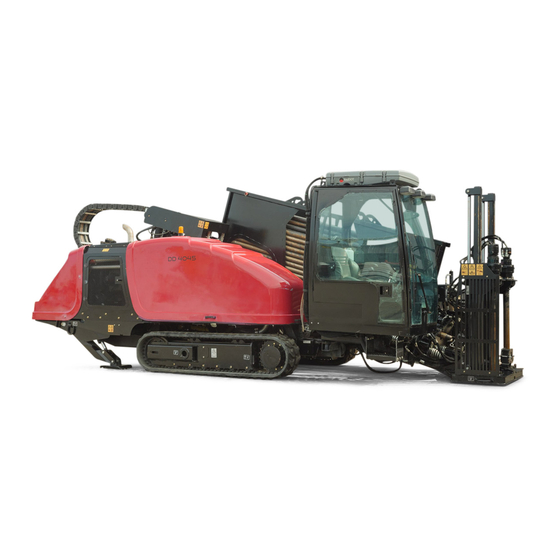
4045 Directional Drill
Software Versions A–C
Model No. 23823/A/C/TE/W—Serial No. 315000001 and Up
Model No. 23825/A/C/TE/W—Serial No. 315000001 and Up
Read this information carefully to learn how to operate
and maintain your product properly and to avoid
injury and product damage. You are responsible for
operating the product properly and safely.
Whenever you need service, genuine Toro parts, or
additional information, contact an Authorized Service
Dealer or Toro Customer Service and have the model
and serial numbers of your product ready.
You may contact Toro directly at www.Toro.com
for product safety and operation training materials,
accessory information, help finding a dealer, or to
register your product.
Main Information Screen
This is the first screen that appears after the initial
splash screen. To navigate between screens, use the
left and right arrows.
1. Drill speed (rpm)
2. Rotary torque
3. Thrust force
© 2019—The Toro® Company
8111 Lyndale Avenue South
Bloomington, MN 55420
Figure 1
4. Engine speed (rpm)
5. Drilling-fluid flow rate
6. Drilling-fluid / Air-hammer
pressure
Register at www.Toro.com.
1. Pipe functions
2. Fuel gauge
3. Limit setting options
4. Select pipe row
Go to the
Mud or Air Hammer Selection Screen (page
12)
to switch between mud pressure and air hammer
functions.
Push button 1 to switch between the pipe functions
pull pipe, push pipe, and neutral.
Push button 5 to switch between thrust force, drill
speed (rpm), and rotary torque limits.
Use the up and down arrows to set the limits for
maximum drill speed (rpm), rotary torque, and thrust
force.
g214633
•
Thrust force: Change the thrust force limit by
pushing 6 or 7.
•
Drill speed (rpm): Change the drill speed rpm limit
by pushing 6 or 7.
•
Rotary torque: Change the rotary torque limit force
by pushing 6 or 7.
Original Instructions (EN)
Form No. 3419-198 Rev B
Software Guide
Figure 2
5. Engine temperature gauge
6. Engine droop
7. Horn
8. Thrust force, drill speed
(rpm), or rotary torque
adjustment
All Rights Reserved *3419-198* B
Printed in the USA
g214634
Advertisement

Related Manuals for Toro DD4045


Summary of Contents for Toro DD4045
- Page 1 Whenever you need service, genuine Toro parts, or additional information, contact an Authorized Service Dealer or Toro Customer Service and have the model and serial numbers of your product ready. You may contact Toro directly at www.Toro.com...
- Page 2 Pulling Pipe in SmartTouch Mode Start the SmartTouch mode with the cam assembly in the home position (row 4 of the pipe box). Important: Ensure that you hold the lower section of the cam rocker switch, on the left joystick, completely down until the action is complete in each step (Figure...
- Page 3 Push buttons 2 and 3 to select the row where you want to place the pipe (Figure g232381 Figure 7 1. Pull pipe 2. Select pipe row Hold the lower section of the rocker switch (Figure 9) until the following 3 things happen (Figure 10): The cam assembly rotates toward the...
- Page 4 Release the rocker switch to proceed to the next Hold the lower section of the rocker switch step in the sequence (Figure 11). (Figure 15) until the arms rotate with the pipe back to the home position and the grippers open as the pipe enters the cam assembly pocket (Figure 16).
- Page 5 Release the rocker switch to proceed to the next Release the rocker switch to proceed to the next step in the sequence (Figure 17). step in the sequence (Figure 20). g231715 g231716 Figure 17 Figure 20 Hold the lower section of the rocker switch Hold the lower section of the rocker switch (Figure 18) until the cam assembly rotates to the...
- Page 6 Pushing Pipe in SmartTouch Mode Start the SmartTouch mode with the cam assembly in the home position (row 4 of the pipe box). Important: Ensure that you hold the lower section of the cam rocker switch, on the left joystick, completely down until the action is complete in each step (Figure...
- Page 7 Release the rocker switch to proceed to the next Release the rocker switch to proceed to the next step in the sequence (Figure 29). step in the sequence (Figure 32). g231718 g231719 Figure 29 Figure 32 Hold the lower section of the rocker switch Hold the lower section of the rocker switch (Figure 30) until the cam assembly fully rotates...
- Page 8 Release the rocker switch to proceed to the next Hold the lower section of the rocker switch step in the sequence (Figure 35). (Figure 39) until the loader arms rotate back and the cam assembly returns to the home position (row 4) (Figure 40).
- Page 9 Hours Screen Options Lubrication and Maintenance Screens Machine Hours Screen To access this screen, push button 3 on the Hours screen. To access this screen, push button 1 on the Hours screen. These screens provide the user with the daily maintenance schedules in the increments listed below.
- Page 10 Settings Screen Options Carriage Settings Screen Push button 1 on the Settings screen. Use this screen to change the carriage settings. Use the up and down arrows to rotate between push pipe, pull pipe, and neutral. Push the OK button to turn SmartTouch™ on and off. g034779 Figure 45 g233212...
- Page 11 Parameters Options Screen Screen Settings Push button 3 on the Settings screen. Push button 6 on the Settings screen to switch between zoom delay, brightness, and day or night The pin number to change the parameters is mode. Use the up and down arrows to adjust the 73236531.
- Page 12 Mud or Air Hammer Selection • The rotary voltage ranges from 0.0 to 8.5 V and can be present for either make (upper icon) or Screen break (lower icon) as the selected rotary joystick is moved. Push button 8 on the Settings screen to access this screen.
- Page 13 • If the engine is shut off, the voltage is measured or lower indicates either sensor failure or incorrect by the Toro controller. calibration. • If the engine is running, the voltage is supplied by engine controller. Auxiliary I/O Screen Engine temperature icon: displays the engine To access this screen push button 5 on the I/O screen.
- Page 14 Travel Pendant I/O Screen Seat switch icon: shows an arrow out when the operator seat is empty; the switch shows a figure icon To access this screen push button 7 on the I/O screen. when you are in the operator seat. The travel pendant screen shows the voltage and •...
- Page 15 Engine Errors Screen Carriage Crash Warning Icon The carriage crash warning screen (Figure To access this screen push button 2 on the Errors and Machine Information screen. appears if the following occurs: • The carriage is in the drill area and you try to This screen displays any engine errors.
- Page 16 Stake Down Cage Warning Icon (CE models only) This icon (Figure 67) displays if the stake down cage door is not closed. g223941 Figure 67...