Bosch RADION B810 Installation Manual
Hide thumbs
Also See for RADION B810:
- Reference manual (62 pages) ,
- Installation manual (2 pages) ,
- Installation manual (4 pages)
Table of Contents
Advertisement
Advertisement
Table of Contents

Related Manuals for Bosch RADION B810


Summary of Contents for Bosch RADION B810
- Page 1 RADION receiver SD B810 Installation manual...
-
Page 3: Table Of Contents
RADION receiver SD Table of contents | en Table of contents Introduction About documentation Bosch Security Systems, Inc. product manufacturing dates General installation Installation workflow Unpacking information Wall tamper switch installation Magnet cover installation Complete installation Maintenance RADION receiver SD... - Page 4 13.1 Installation considerations RADION contact RM 14.1 Installation considerations RADION specialty 15.1 Applications for this product 15.2 Installation consideration RADION universal transmitter 16.1 Installation considerations 16.2 Reed switch settings RADION keyfob 2020.05 | 13 | F.01U.261.834 Bosch Security Systems B.V.
- Page 5 RADION receiver SD Table of contents | en 17.1 RADION keyfob FB 17.2 RADION keyfob TB RADION panic FP Appendices Bosch Security Systems B.V. 2020.05 | 13 | F.01U.261.834...
-
Page 6: Introduction
RADION documentation. Icons and symbols When you see the following logo in the RADION graphical installation guides listed in Table 3.1, refer to the appropriate section in this document. 2020.05 | 13 | F.01U.261.834 Bosch Security Systems B.V. -
Page 7: About Documentation
Refer to the Appendices, page 91 for more information. About documentation Copyright This document is the intellectual property of Bosch Security Systems, Inc. and is protected by copyright. All rights reserved. Trademarks All hardware and software product names used in this document are likely to be registered trademarks and must be treated accordingly. -
Page 8: General Installation
Wire all objects according to their specifications. – RADION devices use batteries of varying types. When installing batteries, observe safety and polarity recommendations as indicated in the documentation for those products. 2020.05 | 13 | F.01U.261.834 Bosch Security Systems B.V. -
Page 9: Installation Workflow
Review signal strength and margin of each point Complete the installation Unpacking information When unpacking the receiver, repeater, or bill trap device, it is important to remove the cardboard insert as illustrated below; Bosch Security Systems B.V. 2020.05 | 13 | F.01U.261.834... -
Page 10: Wall Tamper Switch Installation
– Failure to insert a screw into the wall tamper slot prevents the wall tamper feature from generating a tamper signal when the transmitter is pulled away from a wall. 2020.05 | 13 | F.01U.261.834 Bosch Security Systems B.V. -
Page 11: Magnet Cover Installation
PIR chapters of this guide. – Magnet testing can be performed by opening or closing the door/window in which the magnet is installed on. Maintenance Bosch Security Systems B.V. 2020.05 | 13 | F.01U.261.834... - Page 12 In the normal operating mode, an alarm can be transmitted only after three (3) minutes have passed since the previous alarm restoral. This 3 minute lockout time reduces unnecessary RF transmissions in high traffic areas, thereby extending battery life. 2020.05 | 13 | F.01U.261.834 Bosch Security Systems B.V.
-
Page 13: Radion Receiver Sd
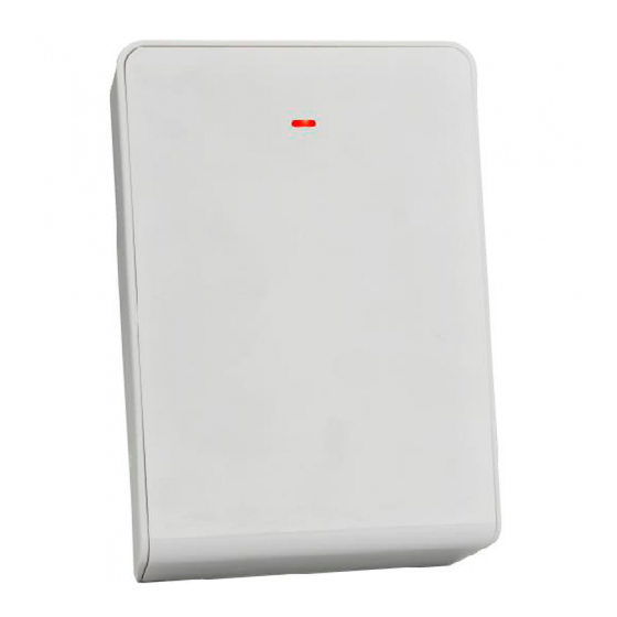
RADION receiver SD RADION receiver SD | en RADION receiver SD The receiver connects RADION wireless peripherals to supported Bosch control panels using the SDI2 bus connection. A compatible control panel powers the receiver through the wiring connection. Features include: –... -
Page 14: Certifications And Approvals
Tab. 3.1: Check-in differences Certifications and approvals Listings and approvals The B810 is UL listed for Commercial/Residential Burglar Alarm Systems, and Household Fire Warning System Units. 2020.05 | 13 | F.01U.261.834 Bosch Security Systems B.V. - Page 15 RFDW-SM/RFDW-SM-CHI standard door/window contact – RRDW-RM/RFDW-RM-CHI recessed door/window contact – RFDL-11/RFDL-11-CHI motion detector – RFPR-12/RFPR-12-CHI motion detector – RFPR-C12/RFPR-C12-CHI motion detector (curtain) – RFUN/RFUN-CHI universal transmitter – RFSM/RFSM-CHI smoke detector – RFKF-FB/RFKF-FB-CHI keyfob Bosch Security Systems B.V. 2020.05 | 13 | F.01U.261.834...
- Page 16 However, there is no guarantee that interference will not occur in a particular installation. If this equipment does cause harmful interference 2020.05 | 13 | F.01U.261.834 Bosch Security Systems B.V.
- Page 17 Conformément à la réglementation d'Industrie Canada, le présent émetteur radio peut fonctionner avec une antenne d'un type et d'un gain maximal (ou inférieur) approuvé pour l'émetteur par Industrie Canada. Bosch Security Systems B.V. 2020.05 | 13 | F.01U.261.834...
-
Page 18: Ul Product Requirements
When selecting a suitable 18 VAC Class 2 plug-in transformer, the following transformers are suggested: – TDC Part No DA-22-18, Primary Rated 120 VAC, 60 Hz, 30 VA, Secondary Rated 18 VAC, 1.22 Amps, 22 VA. 2020.05 | 13 | F.01U.261.834 Bosch Security Systems B.V. - Page 19 8 Hours for HOLD UP Burglar Alarms – 4 Hours for Burglar Alarm Mercantile Installations RADION glassbreak Notice! The RFGB-A has not been investigated by UL, and not part of a UL Listed system. Bosch Security Systems B.V. 2020.05 | 13 | F.01U.261.834...
- Page 20 When programming the bill trap, special programming for a hold up device is required. Program the point as follows: – P## Type = 2 (Point is constantly armed regardless of the status of the system). 2020.05 | 13 | F.01U.261.834 Bosch Security Systems B.V.
- Page 21 P## Type = 1 Instant on open or short (Point is constantly armed regardless of the status of the system). – ᅳP## Invisible Point/Silent Bell = Yes (Keypads do not display alarm activity from this point). Bosch Security Systems B.V. 2020.05 | 13 | F.01U.261.834...
-
Page 22: Installation
Install the receiver in a location away from metal objects. Metal objects (duct work, wire mesh screens, boxes) reduce RF range. 3.4.1 Configuration RADION Wireless System operates on a radio frequency of 433.42 MHz. 2020.05 | 13 | F.01U.261.834 Bosch Security Systems B.V. - Page 23 If the RADION keyfob no longer operates as originally programmed, try resetting the receiver. RF IDs remain active if previously enrolled, and will not have to be re-enrolled when resetting the receiver. Bosch Security Systems B.V. 2020.05 | 13 | F.01U.261.834...
-
Page 24: Base Installation
The base must be installed to provide plenty of accessible space to insert a flat- headed screwdriver, and remove the receiver cover for maintenance and troubleshooting. 2020.05 | 13 | F.01U.261.834 Bosch Security Systems B.V. -
Page 25: Wiring Considerations
Ensure that the wiring used meets the following specifications: – Four-conductor unshielded 0.65 mm (22 AWG) to 2.0 mm (18 AWG) maximum. – Wire length must not exceed 243 m (800 ft) from the control panel Bosch Security Systems B.V. 2020.05 | 13 | F.01U.261.834... -
Page 26: Programming Wireless Points In The Control Panel
Using Remote Programming Software (RPS) on a supported laptop computer, or – Compatible keypad devices to enable your points A “point” can be a detection device, or a group of devices connected to your security system. 2020.05 | 13 | F.01U.261.834 Bosch Security Systems B.V. - Page 27 The workflow listed below is a generic representation of the programming/enablement process. Refer to the Points Menu Parameters section inside the Keypad Installer Menu chapter of the compatible Bosch control panel Installation and System Reference Guides, or Points - Point Assignments in RPS Help File for more information.
- Page 28 Assign the attributes of the point index (how the device will respond to various circumstances). Save changes and exit the menu. Signal strength test (for repeaters) From the keypad, access the Wireless Menu, and select Diagnostics. 2020.05 | 13 | F.01U.261.834 Bosch Security Systems B.V.
-
Page 29: Enroll Point Rf Id For Wireless Points (Auto-Learn Mode)
Perform the following to enroll in the RF ID: From the keypad, access the Wireless Menu, and select the Points menu option. If adding a repeater, select the Repeater menu option. Bosch Security Systems B.V. 2020.05 | 13 | F.01U.261.834... -
Page 30: Walk Test (For Motion Detectors)
Although generally not required, if masking is desired, the lens diagram shows the appropriate areas to be masked. Use an opaque material (such as, electrical tape) to mask the desired areas. 2020.05 | 13 | F.01U.261.834 Bosch Security Systems B.V. -
Page 31: Signal Level And Margin
The concept of signal margin can be related to two people conversing in a room; when the room is quiet they hear each other clearly and the “signal margin” would be very high. In a Bosch Security Systems B.V. 2020.05 | 13 | F.01U.261.834... - Page 32 From the keypad, access Wireless Menu, and select Diagnostics. Select RF Repeaters. Select the Signal menu and choose the repeater. Various sub-categories display including: – Signal strength – Level – Margin Exit the menu. 2020.05 | 13 | F.01U.261.834 Bosch Security Systems B.V.
-
Page 33: Complete The Installation
. The receiver remains in this state as long as the communication link is present, and no other issues are present that would prevent the receiver from operating in a normal condition. LED condition State description Bosch Security Systems B.V. 2020.05 | 13 | F.01U.261.834... - Page 34 3 pulse failure. This error could be a (Communication error) result of either: – A communication failure between the control panel and receiver, or – An invalid address switch setting 2020.05 | 13 | F.01U.261.834 Bosch Security Systems B.V.
-
Page 35: Leds
Indicates there is a power failure to the receiver. Check the wire connections for proper wiring. 3.5.1 LEDs The receiver utilizes an external LED indicator to status the operation of the receiver. Refer to the table below for LED descriptions. Bosch Security Systems B.V. 2020.05 | 13 | F.01U.261.834... - Page 36 A communication failure with internal Off states hardware components within the (Trouble state) receiver Flash 3 times: Indicates the receiver has obtained a new radio frequency ID while in “Learn Mode”. 2020.05 | 13 | F.01U.261.834 Bosch Security Systems B.V.
-
Page 37: Specifications
Tab. 3.2: Specifications 3.6.1 Battery requirements Use sealed lithium or alkaline batteries for supported RADION wireless system peripherals. Replace the batteries annually to ensure optimal performance. Bosch Security Systems B.V. 2020.05 | 13 | F.01U.261.834... - Page 38 RADION PIR C CR123A Lithium 3 VDC motion detector RADION Non- Lithium 3.7 VDC repeater replacea polymer nominal RADION CR123A Lithium 3 VDC smoke detector RADION CR123A Lithium 3 VDC universal transmitter 2020.05 | 13 | F.01U.261.834 Bosch Security Systems B.V.
- Page 39 RADION CR123A Lithium 3 VDC glassbreak detector RADION CR2032 Lithium 3 VDC keyfob FB key (coin fobs cell) RADION CR2032 Lithium 3 VDC keyfob TB key (coin fobs cell) Bosch Security Systems B.V. 2020.05 | 13 | F.01U.261.834...
- Page 40 RADION panic CR123A Lithium 3 VDC FP panic button RADION CR123A Lithium 3 VDC Smoke and Heat RADION Heat CR123A Lithium 3 VDC RADION CO Alkaline 1.5 VDC Tab. 3.3: Battery requirements 2020.05 | 13 | F.01U.261.834 Bosch Security Systems B.V.
-
Page 41: Radion Repeater
Re-apply the AC and battery power to the current repeater. Repeat steps 2-5 until all repeaters in your environment have gone through the verification process and a redundant communication path is confirmed. Bosch Security Systems B.V. 2020.05 | 13 | F.01U.261.834... -
Page 42: Installation Considerations
139.70 mm x 209.60 mm x 31.80 mm (5.50 in x 8.25 in x 1.25 in) Compatible plug-in transformers for use with the RFRP-A repeater within US installations: These transformers are approved by UL: 2020.05 | 13 | F.01U.261.834 Bosch Security Systems B.V. - Page 43 RADION receiver SD RADION repeater | en – BOSCH CX4010 Plug-in Transformer – (F.01U.020.504) primary rated 110 VAC primary voltage input, 18 VAC, 22 – BOSCH D1640 Plug-in Transformer – (4.998.125.832) primary rated 16.5 VAC, 40 VA – MG Electronic (MGT-1640), primary rated 120 VAC, 60 Hz, 0.48 Amps, secondary rated 16.5 VAC, 40 VA...
-
Page 44: Leds
– A communication failure within internal continuous pulse hardware components inside the between On and receiver Off states with a short delay after the 2 pulse Tab. 4.5: LED descriptions 2020.05 | 13 | F.01U.261.834 Bosch Security Systems B.V. - Page 45 RADION receiver SD RADION repeater | en Bosch Security Systems B.V. 2020.05 | 13 | F.01U.261.834...
-
Page 46: Radion Glassbreak
(3/32 in to 1/4 in) Tempered 3.2 mm to 6.4 mm (1/8 in to 1/4 in) Laminated 3.2 mm to 6.4 mm (1/8 in to 1/4 in) Wired 6.4 mm (1/4 2020.05 | 13 | F.01U.261.834 Bosch Security Systems B.V. -
Page 47: Installation Considerations
In a suitable environment: temperature between -18 and 50゚C (0 and 120゚F); and humidity between 10 and 90% non-condensing Avoid mounting the detector in: – Glass airlocks and glass vestibule areas – Humid rooms Bosch Security Systems B.V. 2020.05 | 13 | F.01U.261.834... -
Page 48: Testing
Each time the sensor alarms, it also goes into test mode for one minute. Initiating test mode with the Sentrol 5709C hand-held tester: 2020.05 | 13 | F.01U.261.834 Bosch Security Systems B.V. - Page 49 Check the battery strength of the hand-held testing device before the test. Bosch Security Systems B.V. 2020.05 | 13 | F.01U.261.834...
- Page 50 When the detector is in normal mode, the LED is off unless a loud sound is detected. Therefore, to ensure the glassbreak has power and that the microphone is functional, perform a simple hand clap test. 2020.05 | 13 | F.01U.261.834 Bosch Security Systems B.V.
-
Page 51: Low Battery
Maintenance Clean the cover with a damp (water) cloth as needed to keep it free of dust and dirt. Always test the sensor after cleaning it. Bosch Security Systems B.V. 2020.05 | 13 | F.01U.261.834... -
Page 52: Radion Tritech
Features include: – 11m x 11m (35 ft by 35 ft) coverage – Flexible mounting height – Compatible with Bosch RADION wireless systems – Draft and Insect immune – Cover activated tamper indication. Optional wall-activated tamper is included Dimension 138.00 mm x 72.00 mm x 64.00 mm... -
Page 53: Mounting Height And Range Adjustment
2.4 m (8.0 ft) -10゚ -7゚ Tab. 6.8: Mounting height Notice! The mounting height must be 2 m (6.5 ft) and the vertical angle must be set at -5゚ for installations containing pets. Bosch Security Systems B.V. 2020.05 | 13 | F.01U.261.834... -
Page 54: Sensitivity Settings
In the normal operating mode, an alarm can be transmitted only after three (3) minutes have passed since the previous alarm restoral. This 3 minute lockout time reduces unnecessary RF transmissions in high traffic areas, thereby extending battery life. 2020.05 | 13 | F.01U.261.834 Bosch Security Systems B.V. - Page 55 Set the adjustment as low as possible for proper catch performance. Adjust the Microwave Range Adjustment Potentiometer to as low a setting as possible for proper catch performance. Bosch Security Systems B.V. 2020.05 | 13 | F.01U.261.834...
- Page 56 Walk test from the opposite direction to determine the coverage pattern boundaries from both sides. When walk test is completed, the detector returns to normal operation after 90 sec of inactivity. 2020.05 | 13 | F.01U.261.834 Bosch Security Systems B.V.
-
Page 57: Radion Pir
Wall and cover tamper Transmits a tamper signal when switch someone removes the device from its base or pulls it away from the wall. Bosch Security Systems B.V. 2020.05 | 13 | F.01U.261.834... -
Page 58: Walk Testing
Refer to the LED table below for LED descriptions. LED condition Cause Steady blue PIR activation (Walk Test) Flashing blue Warm-up period after power-up 2020.05 | 13 | F.01U.261.834 Bosch Security Systems B.V. - Page 59 Walk Test mode is ending. This occurs when there is no activity in the sensor’s coverage pattern during the 90-sec interval. When walk testing is completed. the detector returns to normal operation after 90 seconds of inactivity. Bosch Security Systems B.V. 2020.05 | 13 | F.01U.261.834...
-
Page 60: Radion Pir C
Wall and cover tamper Transmits a tamper signal when switch someone removes the device from its base or pulls it away from the wall. 2020.05 | 13 | F.01U.261.834 Bosch Security Systems B.V. -
Page 61: Walk Testing
Refer to the LED table below for LED descriptions. LED condition Cause Steady blue PIR activation (Walk Test) Flashing blue Warm-up period after power-up Bosch Security Systems B.V. 2020.05 | 13 | F.01U.261.834... - Page 62 Walk Test mode is ending. This occurs when there is no activity in the sensor’s coverage pattern during the 90-sec interval. When walk testing is completed. the detector returns to normal operation after 90 seconds of inactivity. 2020.05 | 13 | F.01U.261.834 Bosch Security Systems B.V.
-
Page 63: Radion Smoke Rfsm2
Callout - Description 1 - Mounting plate 2 - Test/Silence button 3 - LED 4 - Sounder For more information, refer to the RADION Life Safety Installation Manual P/N: F.01U.361.555. Bosch Security Systems B.V. 2020.05 | 13 | F.01U.261.834... -
Page 64: Radion Co
POWER Callout - Description 1 - LEDs 2 - Test/Silence button 3 - Sounder 4 - Mounting plate For more information, refer to the RADION Life Safety Installation Manual P/N: F.01U.361.555. 2020.05 | 13 | F.01U.261.834 Bosch Security Systems B.V. -
Page 65: Radion Heat
Callout - Description 1 - Mounting plate 2 - Test/Silence button 3 - LED 4 - Sounder For more information, refer to the RADION Life Safety Installation Manual P/N: F.01U.361.555. Bosch Security Systems B.V. 2020.05 | 13 | F.01U.261.834... -
Page 66: Radion Smoke
Minimum of 5 years or greater Device testing To ensure proper functionality, the device must be tested at least once every year. Sensitivity 0.14+/- 0.04 bM/m (0.97 – 2.99%/ft obscuration – RFSM-A only) 2020.05 | 13 | F.01U.261.834 Bosch Security Systems B.V. - Page 67 Sounder 85 dBA at 3 m Self-diagnostics Monitors detector sensitivity and feature operational status. Frequency 433.42 MHz Tab. 12.14: Specifications Figure 12.1: Smoke detector 1 ᅳ High intensity LED 2 ᅳ Test/Silence button Bosch Security Systems B.V. 2020.05 | 13 | F.01U.261.834...
-
Page 68: Battery Replacement
The detector includes a Sensitivity Level Test mode for determining the detector’s sensitivity: Press and hold the Test/Silence button for 4 sec. The LED flashes 1 to 9 times. 2020.05 | 13 | F.01U.261.834 Bosch Security Systems B.V. -
Page 69: Test/Silence Button
After a few minutes, the sounder and alarm resume if smoke is still present. Remote monitoring station alarm test Press the button for fifteen (or 20) seconds to send a fire alarm signal to the remote monitoring station. Bosch Security Systems B.V. 2020.05 | 13 | F.01U.261.834... -
Page 70: Led
Remove the detector from the mounting base. Remove the batteries. Slide a slotted screwdriver into the slot on the detector cap and gently push down to pry off the cap. Figure 12.2: Remove the detector cap 2020.05 | 13 | F.01U.261.834 Bosch Security Systems B.V. - Page 71 If the batteries are not installed properly, the detector will not fit onto the mounting base. Ensure that the batteries are properly installed. Mount the detector onto the mounting base. 10. Test the detector’s sensitivity. Bosch Security Systems B.V. 2020.05 | 13 | F.01U.261.834...
-
Page 72: Radion Contact Sm
UL only: 0゚C to +49゚C (+32゚F to +120゚ Relative humidity 0% to 93% (non-condensing) Wall and Cover Transmits a tamper signal when Tamper Switch someone removes the device from its base or pulls it away from the wall. 2020.05 | 13 | F.01U.261.834 Bosch Security Systems B.V. -
Page 73: Installation Considerations
When installing the magnet base, install the face of the magnet base flush to the surface edge of the installation location. This prevents damage to the magnet plastic base whenever a window or door is opened. Bosch Security Systems B.V. 2020.05 | 13 | F.01U.261.834... - Page 74 (wood or metal). Notice! The content in the Installation Guide table applies to EN installations. 2020.05 | 13 | F.01U.261.834 Bosch Security Systems B.V.
-
Page 75: Radion Contact Rm
(0.87 in x 1.10 in x 0.59 in) Relative humidity 0% to 93%, non-condensing Temperature Functional range: -10°C to +49°C (+14°F (operating) to +120°F) UL only: 0゚C to +49゚C (+32゚F to+120゚F) Frequency 433.42 MHz Tab. 14.18: Specifications Bosch Security Systems B.V. 2020.05 | 13 | F.01U.261.834... -
Page 76: Installation Considerations
Guide is a graphical table along with the X ᅳ Y coordinates graphic. Use the table in conjunction with the graphic to determine desired distances between the magnet and the transmitter based on the type of installation. 2020.05 | 13 | F.01U.261.834 Bosch Security Systems B.V. -
Page 77: Radion Specialty
Relative humidity Up to 93%, non-condensing Temperature Functional range: -10°C to +49°C (+14°F (operating) to +120°F) UL only: 0゚C to +49゚C (+32゚F to+120゚F) Frequency 433.42 MHz Tab. 15.19: Specifications Bosch Security Systems B.V. 2020.05 | 13 | F.01U.261.834... -
Page 78: Applications For This Product
For this occasion, the hook and loop may be a more suitable mounting technique. 2020.05 | 13 | F.01U.261.834 Bosch Security Systems B.V. -
Page 79: Installation Consideration
Warning! It is important to check the Velcro strips on a weekly basis for wear and replace when appropriate in order to prevent potential false alarms. Bosch Security Systems B.V. 2020.05 | 13 | F.01U.261.834... -
Page 80: Radion Universal Transmitter
Temperature Functional range: -10°C to +49°C (operating) (+14°F to +120°F) UL only: 0゚C to +49゚C (+32゚F to+120゚ Relative Humidity 0% to 93% (non-condensing) 2020.05 | 13 | F.01U.261.834 Bosch Security Systems B.V. -
Page 81: Installation Considerations
3 ᅳ Input disabled – no contact 16.1 Installation considerations You have a variety of installation options to consider when installing the device. You must acknowledge the unique installation approach prior to installation. Some installation considerations include: Bosch Security Systems B.V. 2020.05 | 13 | F.01U.261.834... - Page 82 Use the table in conjunction with the graphic to determine desired distances between the magnet and the transmitter based on the type of installation (wood or metal). Notice! The content in the graphical table applies to EN installations. 2020.05 | 13 | F.01U.261.834 Bosch Security Systems B.V.
-
Page 83: Reed Switch Settings
Failure to do so may result in unexpected operation of the device. Figure 16.2: Reed switch Callout ᅳ Description 1 ᅳ No jumper disables the internal reed switch 2 ᅳ Jumper on enables the internal reed switch Bosch Security Systems B.V. 2020.05 | 13 | F.01U.261.834... -
Page 84: Radion Keyfob
Encrypted keyfobs Non-encrypted keyfobs RFKF-FBS (P/N: RFKF-FB (P/N: F.01U.253.609) F.01U.313.182) RFKF-TBS (P/N: RFKF-TB (P/N: F.01U.260.847) F.01U.313.185) Encrypted keyfobs Non-encrypted keyfobs RFKF-FBS-CHI (P/N: RFKF-FB-CHI (P/N: F.01U.313.184) F.01U.253.626) RFKF-TBS-CHI (P/N: RFKF-TB-CHI (P/N: F.01U.313.187) F.01U.260.848) 2020.05 | 13 | F.01U.261.834 Bosch Security Systems B.V. - Page 85 Please note, the battery does not come installed. Refer to the specification table for the correct battery type when replacing an old battery. Keyfob buttons Refer to your control panel’s documentation to program the functions of the programmable buttons. Bosch Security Systems B.V. 2020.05 | 13 | F.01U.261.834...
- Page 86 Uniquely coded arm and disarm buttons – Panic alarm – LED indicator – Programmable option buttons The RFKF-FBS-CHI keyfob includes synchronized encryption and is compatible only with RADION receivers having firmware v1.3 or higher. 2020.05 | 13 | F.01U.261.834 Bosch Security Systems B.V.
- Page 87 To operate these buttons, simply press and hold either button for at least one sec in order for the desired feature to work. – Uniquely coded arm and disarm buttons – Panic alarm – LED indicator Bosch Security Systems B.V. 2020.05 | 13 | F.01U.261.834...
- Page 88 The RFKF-TBS-CHI keyfob includes synchronized encryption and is compatible only with RADION receivers having firmware v1.3 or higher. Figure 17.2: Keyfob buttons and LED 1 ᅳ Arm button 2 ᅳ LED 3 ᅳ Disarm button 2020.05 | 13 | F.01U.261.834 Bosch Security Systems B.V.
- Page 89 UL only: 0゚C to +49゚C (+32゚F to +120゚F) Relative Humidity 0% to 93% (non-condensing) Tamper switch Transmits a tamper signal when an unauthorized person removes the detector from its base or attempts to remove the cover. Bosch Security Systems B.V. 2020.05 | 13 | F.01U.261.834...
- Page 90 | RADION panic FP RADION receiver SD Frequency 433.42 MHz 2020.05 | 13 | F.01U.261.834 Bosch Security Systems B.V.
- Page 91 Pet friendly (appropriate height and weights below graphic. Point away from rotating machines. Point away from objects that rapidly change temperature Do not mount the device that has direct exposure to sunlight. Bosch Security Systems B.V. 2020.05 | 13 | F.01U.261.834...
- Page 92 | Appendices RADION receiver SD Do not point toward window. Intended for indoor use only. Electrostatic discharge symbol Symbol against disposing batteries into the garbage Humidity range Temperature range Frequency range 2020.05 | 13 | F.01U.261.834 Bosch Security Systems B.V.
- Page 93 RADION receiver SD Appendices | en Duration of time Questions are answered in the reference guide. Universal sign for connecting or disconnecting power. Universal sign for connecting to a power source. Battery-related information. Bosch Security Systems B.V. 2020.05 | 13 | F.01U.261.834...
- Page 94 | Appendices RADION receiver SD Perform a walk test Walk test has concluded Device has wall tamper detection. 2020.05 | 13 | F.01U.261.834 Bosch Security Systems B.V.
- Page 96 Bosch Security Systems, Inc. Bosch Sicherheitssysteme GmbH 130 Perinton Parkway Robert-Bosch-Ring 5 Fairport, NY 14450 85630 Grasbrunn Germany www.boschsecurity.com © Bosch Security Systems, Inc., 2020...