
Related Manuals for Philips TeleMon B M2636B


Summary of Contents for Philips TeleMon B M2636B
- Page 1 M2636B TeleMon B Monitor Service Manual Part Number M2636-90034 Printed in the U.S.A. December, 2001 First Edition...
- Page 2 This document contains proprietary information which is protected by copyright. All Rights Reserved. Reproduction, adaptation, or translation without prior written permission is prohibited, except as allowed under the copyright laws. Copyright Philips Medical Systems, 1999-2001 All rights reserved. Printed in U.S.A. December, 2001 Part No.
- Page 3 Printing History Printing History New editions of this document incorporate all material updated since the previous edition. Update packages may be issued between editions and contain replacement and additional pages to be merged by a revision date at the bottom of the page.
- Page 4 About this Book C User’s Guide. See also the Information Center User’s Guide for operating information on the Information Center. Document Warnings Conventions Warning Warnings are information you should know to avoid injuring patients and personnel. Cautions Caution Cautions are information you should know to avoid damaging your equipment and software.
-
Page 5: Table Of Contents
Contents 1. Introduction........... . . 1-1 Overview and Functional Description . - Page 6 3. Site Planning—Specific Requirements ....... 3-1 Environmental Considerations ........... 3-2 Temperature .
- Page 7 Upgrading the Software ........... . 5-19 Getting Started .
- Page 8 The Battery Compartment ..........5-45 Removal of Battery Compartment .
- Page 9 9. Safety and System Specifications........9-1 Safety Information .
- Page 10 Contents-6...
-
Page 11: Introduction
Introduction Overview and Functional Description The M2636B TeleMon Monitor is a telemetry extension device providing non- invasive blood pressure (NBP) capability, a bedside/patient-side display, and isolated line power or battery power to extend the M2601A Telemetry Transmitter battery life. As part of the Telemetry System, TeleMon with a docked transmitter provides local display of ECG waveforms, a pleth wave, a delayed/annotated ECG wave, heart rate, %SpO2, and NBP while simultaneously transmitting ECG, %SpO2 and NBP via a unidirectional RF telemetry link to the Information Center. -
Page 12: A Quick Description Of The Monitor
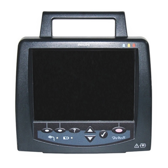
A Quick Description of the Monitor A Quick Description of the Monitor Front of TeleMon Handle NBP Connector Transmitter Docking Recess Battery Compartment Back of TeleMon NBP Cuff Holder Power ON/OFF AC Power Connector* Product Label (18V, 1.83A) Upgrade Port Speaker (underneath) Use only a TeleMon-specific power supply. -
Page 13: Direct Action Keys
A Quick Description of the Monitor • Help key - provides access to operational information during product use. Below the keys, two indicators provide information on the power status of the monitor. RECORD at Central SUSPEND HELP Input Keys START NBP (Silence) STOP NBP Battery Charge Status... -
Page 14: Indicators
A Quick Description of the Monitor Indicators AC Power On/Green—AC power is connected Off—No AC power is connected. Battery Charge Status On/Yellow—Charging the battery On/Blinking Yellow—Initiating communication with the battery, or error condition Off—No charging because either no battery or battery charged Main Screen The Main Screen presents the data in graphical and alphanumeric formats. -
Page 15: Major Assemblies
A Quick Description of the Monitor Other information on the Main Screen includes alarm and information message status, battery and AC power status, and access to monitor setup and service functions. Information Message Battery Gauge Alarm Status—Central AC Power ON Setup &... -
Page 17: Hardware And Software Description
Hardware and Software Description Hardware The following is a summary of the major TeleMon subassemblies. Front Panel The Front Panel Assembly (Figure 5-3 on page 5-31) contains: Assembly • Molded plastic front housing • Anti-glare panel bonded to the inside of the window in the front housing. •... -
Page 18: The Nbp Board
Hardware – When OFF, applies line power to the battery for charging if the External Power Supply is connected. Only the various power and battery indicators are functional. – When OFF, shuts off all power if the External Power Supply is not connected. The coin battery on the Main Board continues to drive the Real Time (RT) clock and some memory circuits. -
Page 19: The Rear Housing Assembly
Hardware • Connector for the Display-to-Main Cable, a ribbon cable conducting LCD control signals from the Main Board. The Rear The Rear Housing Assembly consists of: Housing • Molded plastic rear housing. Assembly • Speaker Mount (Figure 5-16 on page 5-44), a formed stainless metal piece bent into extensions for the Speaker mount and the data path reflector. -
Page 20: Software
Software Software TeleMon interfaces to the Information Center using an RF link provided by the transmitter and an SDN interface provided by the Receiver Mainframe. However, this link is for clinical purposes only. There is a serial port on the bottom of the rear housing of TeleMon, for use in upgrading software. -
Page 21: Site Planning-Specific Requirements
Site Planning—Specific Requirements This chapter provides an overview of site planning for your telemetry system. It includes the following sections: • Environmental Considerations ........3-2 •... -
Page 22: Environmental Considerations
Environmental Considerations Environmental Considerations The monitor should be used in an area reasonably free from vibration, dust, corrosive or explosive gases, and extremes of temperature and humidity. The following paragraphs give information concerning environmental considerations. Temperature The monitor operates within specifications at ambient temperatures between 0 and 35 Celsius. -
Page 23: Power Requirements
Power Requirements Power Requirements The monitor is a mobile extension of the Telemetry System and can display and broadcast information through the antenna on battery power alone for up to a five hours. However, for bedside use it should be connected to a grounded wall outlet through its own external power supply. -
Page 25: Installation
Installation This chapter describes the alternatives available for the installation of a TeleMon monitor and its External Power Supply. • Placement on a Flat Surface ....... 4-2 •... -
Page 26: Placement On A Flat Surface
Placement on a Flat Surface Placement on a Flat Surface The easiest and most mobile way to mount the TeleMon is simply to stand it on a flat surface. The monitor needs to be visible and in a safe place, as free as possible from the danger of accidental pulling, knocking over, or spilling of fluids. -
Page 27: Mounting On A Pole
Mounting on a Pole Mounting on a Pole Mounting on an IV pole combines mobility with stability. The External Power Supply can be mounted apart or near the TeleMon on the same pole. For example, mount the power supply at the bottom of the IV pole. The power input cord must run from the TOP of the power supply to the monitor, to Note—... -
Page 28: Use Of Pole Clamp With External Power Supply
Mounting on a Pole Warning Warning Do not mount the TeleMon below fluids, which may drip or leak onto it. Use of Pole Clamp with External Power Supply Figure 4-2 Mounting Power Supply with Pole Clamp Step 1. Screw the External Power Supply Bracket to a Pole Clamp with the screws provided. -
Page 29: Mounting On The Wall (General)
Mounting on the Wall (General) Mounting on the Wall (General) Wall mounting requires the most preparation and is the most stable, but least mobile, configuration. Caution These mounting instructions are neither applicable in California nor sanctioned by the California OSHPD for installation in the State of California, U.S.A., in conformance to that state’s requirements for seismic protection. - Page 30 Mounting on the Wall (General) Warning Warning Existing wall construction and reinforcement: The wall mounts must be capable of supporting four times the specified weight capacity after they have been properly installed. To provide this support in plaster, plasterboard, or gypsum board walls, the wall covering must be removed in the area of work and a reinforcement must be provided within the wall structure.
- Page 31 Mounting on the Wall (General) Warning Warning Do not install wall mount onto solid brick walls or tile veneer walls, or onto weak or crumbly wall material such as cinder blocks, brick, brick veneer, clay or rubble construction. Installation...
-
Page 33: Troubleshooting, Service And Repair
Troubleshooting, Service and Repair This chapter describes maintenance, troubleshooting and service. It includes the following sections: • Troubleshooting ......... 5-2 –... -
Page 34: Troubleshooting
Troubleshooting Troubleshooting Purpose This section provides troubleshooting instructions for TeleMon. To properly troubleshoot TeleMon, a clear understanding of the Telemetry system is required. When troubleshooting TeleMon consider that problems can occur because of: • Equipment malfunctions: hardware failures, etc. • Application faults: usually leads off, battery problems, ECG equipment malfunction, transmitter malfunction, %SpO malfunction. -
Page 35: Suspending Patient Alarms
Troubleshooting Suspending You can suspend central telemetry alarms from TeleMon for 3 minutes to prevent false alarms Patient Alarms from occurring during a change of electrodes or other activity that could cause motion artifact alarms. Visual Indicators on TeleMon for Suspended Alarms: Message CENTRAL ALARMS SUSPENDED displayed in red on top banner •... - Page 36 Troubleshooting The following table lists all of the information signals (in alphabetic order) that could appear in the information message area at the top center of the TeleMon display. Table 5-1. TeleMon Information Messages Information Message Problem Corrective Action CHARGE MON BAT TeleMon battery is <= 25%.
- Page 37 Troubleshooting Table 5-1. TeleMon Information Messages Information Message Problem Corrective Action NBP CUFF Cuff pressure increased above Remove cuff from patient and OVERPRESS overpressure safety limits disconnect from tubing. Gently expel any air. [If water in cuff, use new cuff.] Reconnect and reapply cuff to patient.
- Page 38 Troubleshooting Table 5-1. TeleMon Information Messages Information Message Problem Corrective Action XMTR FAIL Error writing TeleMon data to Replace transmitter and contact transmitter eeprom. service. SPO2 EQUIP MALF Malfunction in the %SpO Change transducer or adapter hardware, or transducer/adapter cable. cable damaged If message persists, replace transmitter.
- Page 39 Troubleshooting Table 5-1. TeleMon Information Messages Information Message Problem Corrective Action SPO2 NOISY SIGNAL Excessive patient movement or Locate sensor at site with less electrical or optical interference is movement. causing irregular pulse patterns Reduce sources of electrical or optical interference. If the above corrective actions are ineffective, consult the Telemetry System Service...
-
Page 40: Self-Test Error And Event Log Messages
Troubleshooting Self-Test The following table describes TeleMon Self-Test Error Messages, and Event Log Messages Error and (available in Service Mode). Additionally, this table provides corrective action to remedy Event Log these failures. Messages There are differences in the severity of event log messages and error messages: •... -
Page 41: Nbp Event Log Error Codes
Troubleshooting Table 5-2. TeleMon Information Messages Message Problem Message Corrective Type Entry Action No/FFX1/Startup.ini Error TeleMon OS Err 2 automatically tries to connect to host PC for service. Reload the TeleMon application software. Cannot find ‘self- Error Irreversible test,’ (or one of its damage to the components). - Page 42 Troubleshooting The following table lists NBP error codes and their appropriate TeleMon message. For details on troubleshooting NBP messages, see “TeleMon Information Messages” on page 5-4. Table 5-3. NBP Event Log Error Codes Additional Error TeleMon Message Probable Cause Information Code No error Valid NBP...
-
Page 43: Power On Self-Test
Troubleshooting Table 5-4. Additional Troubleshooting Tips Issue Probable Cause Display looks dark If the display looks dark even after adjusting the brightness, it’s possible the display needs to be replaced. The display’s estimated half-life is approximately two years. (For details, see “The Display”... -
Page 44: Service Mode
Service Mode Service Mode This section covers TeleMon’s Service Mode. Service mode presents all the device setup functions in the Device Setup Menu. All settings selected in the Device Setup Menu are saved once you exit the Setup Menu and are retained even after a power cycle. -
Page 45: Entering Demo Mode
Service Mode Caution Current settings will be lost when standard unit settings are restored. Press Go. Step 2. Step 3. Press Accept or Cancel at the confirmation dialog box. If you press Accept, a message appears when the restore completes. Press Done to return to the Device Setup menu. -
Page 46: Performing Service Functions
Service Mode If you remove the transmitter and insert a different one, press Update to update the Step 4. display with information from the new transmitter. Press Done to exit. Step 5. Performing This section describes the service functions that are password-protected. When you select Service TeleMon and Transmitter Service from the Device Setup Menu, you are prompted to enter the Functions... - Page 47 Service Mode Troubleshooting, Service and Repair 5-15...
-
Page 48: Viewing The Event Log
Service Mode Viewing the Displaying the event log is useful during troubleshooting. Events that are logged include: Event Log • Monitor mode start • Watchdog timer arming • Watchdog timer resets • System exception resets • Battery critically low shutdown events •... -
Page 49: Nbp Diagnostics, Calibration
Service Mode Step 12. Before disconnecting, make sure that the RunTimeLog.txt file displays in the destination folder. (The file is standard text accessible through Notepad, or a similar application.) Step 13. Rename the log files on the PC using the following format: –... -
Page 50: Conducting Nbp Calibration
Service Mode Step 7. To exit Setup, press Done twice and then press Accept. Conducting NBP To conduct the calibration, you will need a manometer pressure generator (BP bulb), and a Calibration T adaptor. It’s also recommended that you use an expansion chamber, or an adult cuff applied around a bottle or other object of appropriate size;... -
Page 51: Upgrading The Software
Service Mode Upgrading TeleMon ships with the appropriate software from the factory. However, it may be necessary the Software to upgrade the monitor’s software while servicing the unit. This section describes how to upgrade the software, for both application and operating system. TeleMon’s monitoring software and its configuration files are stored separately from the operating system. -
Page 52: Setting Up The Host Computer
Service Mode Table 5-5. Software Installation Then you need to enable or disable see “Enabling/Disabling ActiveSync connections, ActiveSync Serial Connections” on page 5-23. you need to download the event log, see “Downloading the Event Log” on page 5-16. Setting Up the To upgrade the TeleMon software, you need a PC with the TeleMon Support Tool and Host Computer Microsoft ActiveSync installed. - Page 53 Service Mode Step 8. When the reinstall screen displays, click Next. Step 9. When the Registry Settings Failed message displays, click OK. Troubleshooting, Service and Repair 5-21...
-
Page 54: Installing The Telemon Support Tool
Service Mode Step 10. Set the baud rate of COM1 to 115K (if you are using a port other than COM1 to connect to TeleMon, set that port’s baud rate to 115K). Installing the The TeleMon Support Tool simplifies the process of upgrading TeleMon’s software, cloning TeleMon settings from one TeleMon to another, and changing the displayed language used by Support Tool... -
Page 55: Installing Telemon's Application Software
Service Mode Step 11. To initiate the download process, press and hold the NBP button, (last button on the right), and turn TeleMon ON. Hold the NBP button down until the download process starts. – If the download doesn’t start, and a time-out error displays on the computer screen, restart the process beginning with step 1. - Page 56 Service Mode Caution Make sure that synch cable is not accidentally disconnected while the application software is being installed. Should this happen, irreversible damage to the main processor board will occur, and you will need to replace it. If the cable is accidentally disconnected, the following error message displays on the TeleMon screen: “Cannot find ‘self-test,’...
-
Page 57: Cloning Settings
Service Mode – A progress bar indicates the status of the upgrade. Step 12. When the upgrade is complete, you can turn TeleMon OFF and remove the cable. Step 13. Replace the upgrade port door and turn TeleMon ON. The application installation process is now complete. -
Page 58: Changing Telemon's Language Display
Using the Battery Reconditioner Changing The Change Language function of the Support Tool allows you to change the language that TeleMon’s TeleMon displays. This might be necessary if your location needs to use more than one Language language. Display Before you can change TeleMon’s language, you must prepare your computer as described in the section “Setting Up the Host Computer”... -
Page 59: Recondition A Battery
Using the Battery Reconditioner Warning Warning Do not use the battery reconditioner in the patient vicinity. Be sure there is no contact between the patient and the charger, including no contact from the charger to a medical care giver to the patient. The Battery Reconditioner can be used for charging or reconditioning the TeleMon battery. -
Page 60: Charging A Battery
Repair Step 3. Press the recondition button. The recondition button is the blue button with the symbol. During reconditioning, the LED flashes yellow. When reconditioning is complete, the LED flashes between yellow and green. Charging a To charge a battery using the Reconditioner, use the following procedure. Battery Step 1. -
Page 61: Overview
Repair Overview Remove Battery (page 5-32) Remove Front Panel Assembly (page 5-33) Remove Chassis Assembly (page 5-35) Working on Chassis Assembly? Remove Main PC Remove Speaker Remove NBP Board Board (page 5-44) (page 5-38) (page 5-42) Remove Battery Remove Inverter Compartment Board (page 5-39) - Page 62 Repair START HERE Install Fan Install Display Assembly Display Installed? Installed? (page 5-48) (page 5-41) Replace Battery Door Battery Door In Place? (page 5-46) Install Inverter Inverter Board Board Installed? (page 5-40) Install Xmitter Xmitter Dock Dock Installed? (page 5-47) NBP Board Install NBP Installed?
-
Page 63: Before You Begin
Repair Rear Housing Assembly Chassis Assembly Front View Chassis Assembly Rear View Front Panel Assembly Figure 5-3 Exploded View of the TeleMon Monitor Before You Before you begin, please keep in mind that the M2636B TeleMon is a carefully engineered, Begin complex measuring instrument, even though compact and easy to use. -
Page 64: The Battery
Repair Caution Your monitor contains components that will be damaged if ESD precautions are not observed. The Battery Figure 5-4 Removing the Battery Removal of Step 1. Open the battery door on the lower right side of the monitor. Battery Step 2. -
Page 65: The Front Panel Assembly
Repair The Front Panel 6mm T-10 6mm T-10 Assembly Rear View 16mm T-10 16mm T-10 Figure 5-5 Unfastening the Front Panel Assembly Removal of Step 1. Place the monitor face-down on a clean, soft surface. Front Panel Step 2. Remove the two 6mm T-10 screws in the handle and the two 16mm T-10 screws near the base. -
Page 66: Installation Of Front Panel
Repair Figure 5-6 Disconnecting the Keyboard-to-Main Cable Step 4. Lift the tabs on the monitor connector to the Keyboard-to-Main Cable to unlock the cable. Pulling the cable out, lift off the Front Panel Assembly. Installation of Note— The monitor must be completely assembled except for the Front Panel Assembly. Only Front Panel the Monitor Assembly, the Front Panel Assembly and the fasteners should remain loose on hand. -
Page 67: The Chassis Assembly
Repair 16mm T-10 screws in the housing. Be sure to tighten in a sequence of opposite corners. The Chassis Assembly 6mm T-10 6mm T-10 Figure 5-7 Detaching the Chassis Assembly Removal of Step 1. Place the monitor on its back. Chassis Step 2. -
Page 68: Installation Of Chassis Assembly
Repair NBP Collar Connector Cable Connectors Figure 5-8 Chassis Assembly Cables Step 4. Unhook the NBP tubing from behind the Speaker Clip. Twist the NBP Tubing Collar Connector to separate the tubing. Half the tubing remains attached to the Rear Housing Assembly and half to the Note—... - Page 69 Repair Note— All the connectors on the Main Board are keyed to the appropriate cable connector. Do not force a connector. If it does not easily fit, it is the wrong connector. Step 1. Stand the Rear Housing Assembly up on the work surface, facing you. Step 2.
-
Page 70: The Nbp Board
Repair The NBP Remove the NBP Board either to replace it or to access the Inverter Board or the Display. The Board Main Board can have been removed or it can be in place. 6 mm T-10 NBP-to-Main Cable Connectors Figure 5-9 Removal of the NBP Board Removal of Step 1. -
Page 71: The Inverter Board
Repair Step 4. If the Main Board is in place, press the connector of the NBP-to-Main Cable into the keyed connector on the Main Board. If the Main Board is not in place, perform this step when you mount the Main Board. The Inverter Remove the Inverter Board to replace it or to access the Display. -
Page 72: Installation Of Inverter Board
Repair Figure 5-11 Removing the Inverter Shield Step 2. Using the T-10 screwdriver, remove the two 4mm T-10 screws holding the Inverter Shield to the Chassis. Step 3. Lift and slide out the Inverter Shield. Inverter-to-Main Cable Inverter-to-Display Cable Connector Figure 5-12 Inverter Board Connections Step 4. -
Page 73: The Display
Repair Note— This cable will run under the NBP Board and must be in place, regardless of whether the Main Board is present. Take it off the Main Board, if necessary. Step 5. If the Main Board is present, connect the Inverter-to-Main Cable to the small keyed female connector on the side of the Main Board closest to the future position of the NBP Board. -
Page 74: The Main Pc Board
Repair Step 2. Start two 6mm T-10 screws in the screw mounts on the right of the chassis. Step 3. Position the Display in front of the Chassis with the ribbon cable to the left (Display-to-main) and the dark side toward you. Insert the slots on the right side of the display under the two screws that were started. -
Page 75: Installation Of Main Board
Repair Step 4. Remove the three 6mm T-10 screws holding the Main Board to the Chassis. Step 5. Lift the Main Board off the Chassis. Installation of Step 1. Place the Chassis face down on the work surface. The face is the side that features Main Board the short screw mounts, to which the Display is attached. -
Page 76: The Speaker
Repair The Speaker Speaker Clip Figure 5-16 The Speaker Removal of Step 1. Inside the Rear Housing, remove the Speaker Clip holding the Speaker to the Speaker mount. Step 2. Twist and pull out the Speaker. Installation of Step 1. Position the Speaker against the mount, making sure the Speaker-to-Main Cable is Speaker on the outside. -
Page 77: The Battery Compartment
Repair The Battery Compartment Bottom of TeleMon 8 mm T-10 Figure 5-17 Removal of the Battery Compartment Removal of Step 1. Remove the four 8mm T-10 screws holding the four feet to the bottom of the Rear Battery Housing and pull the feet off. Compartment Step 2. -
Page 78: Installation Of Battery Compartment
Repair Hint— The Battery Door must be open, and the serial port door must have been removed. Step 3. Remove the pin holding the Battery Connector to the compartment. Installation of Step 1. Stand the Rear Housing up with the open side facing you. Battery Step 2. -
Page 79: The Transmitter Dock
Repair Step 2. Snap the other door post into its slot, pushing up from the bottom. Transmitter Dock 16 mm T-10 Figure 5-19 The Transmitter Dock Removal of Step 1. Remove the two 16 mm T-10 screws holding the dock to the case. Transmitter Step 2. -
Page 80: The Fan Assembly
Repair Note— Before you insert the fasteners, make sure the Fan-to-Main Cable and the NBP Tubing run outward over the top of the dock. The Fan Assembly Removal of Step 1. If the NBP Tubing is in place, remove it from the supporting channel of the Speaker Fan Assembly Mount. - Page 81 Repair Caution The adhesive on the splash guard is very strong. Therefore, be very careful when installing it. Do not reposition the splash guard. If you make a mistake when installing the splash guard, remove it and install a new one. Step 3.
- Page 82 Repair 5-50 Troubleshooting, Service and Repair...
-
Page 83: Test And Inspection Matrix
Test and Inspection Matrix This chapter includes the Test and Inspection Matrix for the M2636B TeleMon Monitor. Tests that require power should be performed with the TeleMon on AC power, but with the battery installed. Test and Inspection Matrix... -
Page 84: M2600A Telemetry System - Test And Inspection Matrix
M2600A Telemetry System - Test and Inspection Matrix M2600A Telemetry System - Test and Inspection Matrix Test Block Test or “Inspection” to Perform Expected Test Results What to Record Name on Service Record Visual Test: Inspect the system (and packing material if The system does not have any V:P or V:F applicable) for obvious signs of damage. - Page 85 M2600A Telemetry System - Test and Inspection Matrix Test Block Test or “Inspection” to Perform Expected Test Results What to Record Name on Service Record Performance Accuracy Test Value displayed on Monitor = Test NBP: If difference <=3mm proceed Step Action to next test Connect the manometer and the pump to the NBP connector.
- Page 86 M2600A Telemetry System - Test and Inspection Matrix Test Block Test or “Inspection” to Perform Expected Test Results What to Record Name on Service Record Linearity Test Value displayed by Monitor = Step Action Reduce the manometer pressure to 150 mmHg. PN:P/x1/x2/x3 Wait 10 seconds for the measurement to stabilize, then...
-
Page 87: Safety Tests
Safety Tests Safety Tests The test procedures outlined in this section are to be used only for verifying safe installation or service of the product in question. The setups used for these tests and the acceptable ranges of values are derived from local and international standards but may not be equivalent. - Page 88 Safety Tests Test Block Name Test or Inspection to perform S(1) System Enclosure Leakage Medical electrical system Current - NC (normal condition) Instrument under test Signal parts Signal parts (**) in- and/or in- and/or output output L (N) Other Instrument Applied part N (L) (*) Not present in Class 2.
- Page 89 Safety Tests Test Block Name Test or Inspection to perform S(2) Protective Earth Instrument under test L (N) N (L) Applied part Insulating pad (*) If equipotential connection present: measure also 50 Hz 25 A or 1.5 Ir with yellow/green E.P. conductor connected. Measures impedance of Protective Earth (PE) terminal to all exposed metal parts of Instrument under Test (IUT), which are for safety reasons connected to the Protective Earth (PE).
-
Page 90: M2600A Telemetry System - When To Perform Test Blocks
M2600A Telemetry System - When to Perform Test Blocks M2600A Telemetry System - When to Perform Test Blocks Service Event Test Block(s) Required When performing..Complete these tests of M2636B. Perform Visual, Power On test block. Installation Repairs affecting the power supply assembly Perform Power On and Safety (2) test blocks. -
Page 91: Parts List
Parts List This chapter includes an orderable parts list for the M2636B TeleMon Monitor. Number Description Part 0950-3769 Transformer between the wall outlet and the TeleMon External Power Supply monitor. 0950-3919 A PC board mounting the electronics for the inverter. Inverter Board 1420-0864 3 V Lithium battery pressed into a holder mounted on the... - Page 92 Number Description Part M2636-40008 Pre-formed plastic part. The door covering the serial upgrade port, visible through an opening in the bottom of Serial Upgrade Door the Rear Housing. M2636-60100 Assembly consisting of pre-formed plastic case, display, Front Panel Assembly antiglare panel, keyboard and keyboard overlay. M2636-60101 Splash guard kit consisting of plastic film with adhesive.
-
Page 93: Maintenance And Cleaning
Maintenance and Cleaning Maintenance Care and maintenance of TeleMon is limited to making sure the unit is clean and inspected to see if the unit damaged should it be dropped or exposed to any other such trauma. In order to keep your Telemon in the best working condition, perform all maintenance activities as described in this manual. -
Page 94: Disinfection Instructions
Maintenance Caution Use only a 10% solution of sodium hypochlorite (bleach) in water as a cleaning fluid. Do not use any other cleansers, such as betadine. Caution Remove the battery and any cables or accessories before you clean TeleMon. Disinfection To disinfect the TeleMon exterior, battery compartment, and transmitter recess, use the Instructions following directions:... -
Page 95: Nbp Calibration
Maintenance NBP calibration should be performed once a year or every 10,000 measurements, whichever Calibration comes first. The calibration procedure is done in the Service Mode of TeleMon. See “NBP Diagnostics, Calibration” on page 5-17 for instructions. Accessories The performance specifications and tolerance of TeleMon are established using our supplied accessories and supplies. - Page 96 Maintenance Description Order Number 3-wire ECG Lead Set • Snap, AAMI for M2601A, 0.7 m (30 inch) M2590A • Grabber, AAMI for M2601A, 0.7 m (30 inch) M2591A • Snap, IEC for M2601A, 0.7 m (30 inch) M2594A • Grabber, IEC for M2601A, 0.7 m (30 inch) M2595A 5-wire ECG Lead Set •...
- Page 97 Maintenance Description Order Number NBP Cuff • Traditional Multi-Patient - Pediatric 40401B • Traditional Multi-Patient - Adult 40401C • Traditional Multi-Patient - Large Adult 40401D • Long-Life Multi-Patient - Pediatric M1572A • Long-Life Multi-Patient - Small Adult M1573A • Long-Life Multi-Patient - Adult M1574A •...
-
Page 99: Safety And System Specifications
Safety and System Specifications Safety Information Warning Warning The equipment is not suitable for use in the presence of a flammable anesthetic mixture with air or with oxygen or nitrous oxide. Warning Warning Possible explosive hazard if used in the presence of flammable anesthetics. Warning Warning No patient alarms are annunciated at the TeleMon. - Page 100 Safety Information Warning Warning Certain failure conditions, such as extended short circuiting, can cause a battery to overheat during normal use. High temperatures can cause burns to the patient and/or user, or cause the battery to flame. If TeleMon becomes hot to the touch, unplug the AC power, turn the device off, and place it aside until it cools.
- Page 101 Safety Information Warning Warning During complete heart block or pacemaker failure (to pace or capture), tall P- waves (greater than 1/5 of the average R-wave height) may be erroneously counted by the arrhythmia algorithm, resulting in missed detection of cardiac arrest.
- Page 102 Safety Information Warning Warning Do not mix transmitter leadsets and transmitter ECG trunk cables. Only use a 5-wire leadset with a 5-lead trunk cable or a 3-wire leadset with a 3-lead trunk cable. If a 5-wire leadset is plugged into a 3-lead trunk cable, only one lead will be monitored by both the Information Center and TeleMon, and there will be no informational notification displayed.
- Page 103 Safety Information Warning Warning Use only approved cuffs and tubing in order to prevent inaccurate data, injury, or damage. All specified cuffs and the TeleMon are protected against the effects of the discharge of a defibrillator. Warning Warning Prolonged series of non-invasive blood pressure measurements in automatic mode may be associated with purpura, ischemia, and neuropathy in the limb wearing the cuff.
-
Page 104: Cautions
Safety Information Warning Warning Although this equipment is shielded against Electromagnetic Interference (EMI), we recommend you avoid the use of other electrically radiating devices in close proximity to this equipment. Warning Warning TeleMons with transmitters that are broadcasting 25 kHz apart interfere with one another at distances of 1-3 feet. -
Page 105: Electro-Magnetic Compatibility
Safety Information Caution The TeleMon NBP may not operate correctly if used or stored outside the relevant temperature or humidity ranges. Caution Do not use any abrasive cleaning materials on any part or component of the TeleMon. Do not clean any part or component of the TeleMon in any overly vigorous or abrasive fashion. -
Page 106: Avoiding Electro-Magnetic Interference
Safety Information reduced level. Air discharges of more than 6 kV to the screws on the rear of the M2636B housing, or to the bottom of the housing, may cause an instrument reset, whereby the product goes through Power-on Self-Test (as if the M2636B were just powered on). -
Page 107: System Specifications
System Specifications System Specifications Intended Use TeleMon is indicated for use in the monitoring, recording, and alarming of multiple physiologic parameters in adult and pediatric patients to gain information for treatment, to monitor adequacy of treatment, or to exclude causes of symptoms. TeleMon is a prescription device for use in healthcare facilities by trained healthcare professionals. -
Page 108: Authorized Europe/Middle East/Africa Representative
System Specifications Authorized Europe/ Philips Medizinsysteme Böblingen GmbH Middle East/Africa Hewlett Packard Str. 2 Representative 71034 Böbingen Germany FAX: (+49) 7031 464 1552 Electrical Specifications Line Power Power Input An external power supply is used. Input 100-250 VAC +6%/-10%; 50-60 Hz +/-6%... -
Page 109: Nbp Measurement Specifications For Telemon B
System Specifications Shipping & Storage Temperature Range 0º C to 60º C (32º F to 140º F) / without battery 0 to 50º C (32 to 122º F) / with battery Altitude Range Up to 3048 m (10,000 ft.) < 90% relative humidity, non-condensing Humidity Range NBP Measurement For ECG, ST, and %SpO... -
Page 110: Explanation Of Symbols
System Specifications Explanation of The following icons can be found on the TeleMon exterior. Symbols Explanation Symbol Consult accompanying documents (including this User’s Guide) and particularly any warning messages. This device complies with the Council Directive 93/42/EEC of 14 June 1993 concerning medical 0123 devices. - Page 111 System Specifications Explanation Symbol Date of Manufacture Direct Current Safety and System Specifications 9-13...
- Page 112 System Specifications 9-14 Safety and System Specifications...