Dell EMC PowerEdge T440 Installation And Service Manual
Hide thumbs
Also See for EMC PowerEdge T440:
- Installation and service manual (156 pages) ,
- Simple operation manual (9 pages) ,
- Manual (150 pages)

Related Manuals for Dell EMC PowerEdge T440


Summary of Contents for Dell EMC PowerEdge T440
- Page 1 Dell EMC PowerEdge T440 Installation and Service Manual Regulatory Model: E30S Series Regulatory Type: E30S002 April 2021 Rev. A06...
- Page 2 A WARNING indicates a potential for property damage, personal injury, or death. © 2017 - 2021 Dell Inc. or its subsidiaries. All rights reserved. Dell, EMC, and other trademarks are trademarks of Dell Inc. or its subsidiaries. Other trademarks may be trademarks of their respective owners.
-
Page 3: Table Of Contents
Contents Chapter 1: Dell EMC PowerEdge T440 system overview..............7 Supported configurations for the Dell EMC PowerEdge T440 system..............7 Front view of the system..............................9 Status LED indicators..............................15 System health and system ID indicator codes...................... 16 Drive indicator codes..............................17 Back view of the system.............................. - Page 4 Installing a drive blank..............................40 Removing a drive carrier.............................41 Installing a drive carrier.............................. 42 Removing the drive from the drive carrier......................43 Installing a drive into the drive carrier........................43 Removing a 2.5-inch drive from a 3.5-inch drive adapter.................44 Installing a 2.5-inch drive into a 3.5-inch drive adapter..................45 Removing a 3.5-inch drive adapter from a 3.5-inch drive carrier..............
- Page 5 Chapter 5: System diagnostics....................110 Dell Embedded System Diagnostics..........................110 Running the Embedded System Diagnostics from Boot Manager..............110 Running the Embedded System Diagnostics from the Dell Lifecycle Controller........110 System diagnostic controls............................110 Chapter 6: Getting help......................112 Contacting Dell EMC............................... 112...
- Page 6 Documentation feedback..............................112 Accessing system information by using QRL......................112 Quick Resource Locator for Dell EMC PowerEdge T440 system..............113 Receiving automated support with SupportAssist ....................113 Recycling or End-of-Life service information......................113 Chapter 7: Documentation resources..................114 Contents...
-
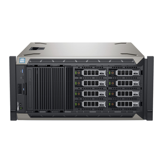
Page 7: Chapter 1: Dell Emc Poweredge T440 System Overview
Dell EMC PowerEdge T440 system overview The Dell EMC PowerEdge T440 system is a dual-socket, 5U rackable tower server that supports up to: ● Two Intel Xeon Scalable Processors ● 16 DIMM slots ● 4 or 8 x 3.5-inch SAS/SATA drive or SSDs, or 16 x 2.5-inch SAS/SATA drive bays (up to 12 Gbps SAS and 6 Gbps SATA) ●... - Page 8 Figure 1. Supported configurations for a Dell EMC PowerEdge T440 system Dell EMC PowerEdge T440 system overview...
-
Page 9: Front View Of The System
Press the power button to gracefully shut down an ACPI- compliant operating system. System identification The System Identification (ID) button is available on the front and back button of the systems. Press the button to identify a system in a rack by Dell EMC PowerEdge T440 system overview... - Page 10 The USB port is USB 3.0 compliant. Optical drive bay Enable you to install drives that are supported on your system. For more information, see the Dell EMC PowerEdge T440 Technical Specifications on the product documentation page. Drive slot Enables you to install TBUs for 8x and 16x backplane configurations, or drive blank in the empty drive slot to maintain proper system cooling.
- Page 11 BIOS using the step through mode. Status LED indicator Indicate the status of the system. For more information, see the panel Dell EMC PowerEdge T440 Technical Specifications on the product documentation page. Dell EMC PowerEdge T440 system overview...
- Page 12 The USB port is USB 3.0 compliant. Optical drive bay Enable you to install drives that are supported on your system. For more information, see the Dell EMC PowerEdge T440 Technical Specifications on the product documentation page. Drive slot Enables you to install TBUs for 8x and 16x backplane configurations, or drive blank in the empty drive slot to maintain proper system cooling.
- Page 13 The USB port is USB 3.0 compliant. Optical drive bay Enable you to install drives that are supported on your system. For more information, see the Dell EMC PowerEdge T440 Technical Specifications on the product documentation page. Drive slot Enables you to install TBUs for 8x and 16x backplane configurations, or drive blank in the empty drive slot to maintain proper system cooling.
- Page 14 BIOS using the step through mode. Status LED indicator Indicate the status of the system. For more information, see the panel Dell EMC PowerEdge T440 Technical Specifications on the product documentation page. Dell EMC PowerEdge T440 system overview...
-
Page 15: Status Led Indicators
The USB port is USB 3.0 compliant. Optical drive bay Enable you to install drives that are supported on your system. For more information, see the Dell EMC PowerEdge T440 Technical Specifications on the product documentation page. Drive slot Enables you to install TBUs for 8x and 16x backplane configurations, or drive blank in the empty drive slot to maintain proper system cooling. -
Page 16: System Health And System Id Indicator Codes
For information about the event and error messages generated by the system firmware and agents that monitor system components, go to qrl.dell.com > Look Up > Error Code, type the error code, and then click Look it up. Dell EMC PowerEdge T440 system overview... -
Page 17: Drive Indicator Codes
NIC ports, and USB and VGA ports. Most of the expansion card ports can be accessed from the back panel. The hot swappable and cabled power supply units are accessible from the back panel. Dell EMC PowerEdge T440 system overview... - Page 18 Ports, panels, or slots Icon Description Power supply unit (2) For more information, see the Dell EMC PowerEdge T440 Technical Specifications on the product documentation page. iDRAC9 dedicated Enables you to remotely access iDRAC. For more information, see network port the iDRAC User’s Guide at www.dell.com/poweredgemanuals.
-
Page 19: Nic Indicator Codes
PCIe expansion card The expansion slots enable you to connect PCI Express expansion slot(6) cards. For more information, see the Dell EMC PowerEdge T440 Technical Specifications on the product documentation page. NIC indicator codes Each NIC on the back of the system has indicators that provide information about the activity and link status. The activity LED indicator indicates if data is flowing through the NIC, and the link LED indicator indicates the speed of the connected network. -
Page 20: Locating The Service Tag Of Your System
Express Service Code and Service Tag. Alternatively, the information may be on a sticker on the chassis of the system. The mini Enterprise Service Tag (EST) is found on the back of the system. This information is used by Dell to route support calls to the appropriate personnel. - Page 21 Figure 12. Locating Service Tag of your system 1. Information tag (top view) 2. Information tag (back view) 3. OpenManage Mobile (OMM) label 4. iDRAC MAC address and iDRAC secure password label 5. Service Tag Dell EMC PowerEdge T440 system overview...
-
Page 22: System Information Label
System information label Dell EMC PowerEdge T440 system overview Figure 13. PowerEdge T440 – Service information... - Page 23 Figure 14. PowerEdge T440 – Service information Dell EMC PowerEdge T440 system overview...
-
Page 24: Chapter 2: Initial System Setup And Configuration
The Integrated Dell Remote Access Controller (iDRAC) is designed to make system administrators more productive and improve the overall availability of Dell systems. iDRAC alerts administrators about system issues and enables them to perform remote system management. This reduces the need for physical access to the system. -
Page 25: Log In To Idrac
Ensure that you change the default username and password after setting up the iDRAC IP address. For more information about logging in to the iDRAC and iDRAC licenses, see the latest Integrated Dell Remote Access Controller User's Guide at www.dell.com/poweredgemanuals. -
Page 26: Downloading Drivers And Firmware
Using iDRAC virtual media www.dell.com/idracmanuals Downloading drivers and firmware Dell EMC recommends that you download and install the latest BIOS, drivers, and systems management firmware on your system. Prerequisites Ensure that you clear the web browser cache before downloading the drivers and firmware. -
Page 27: Chapter 3: Installing And Removing System Components
Damage due to servicing that is not authorized by Dell is not covered by your warranty. Read and follow the safety instructions that are shipped with your product. -
Page 28: Before Working Inside Your System
NOTE: It is recommended that you always use an antistatic mat and antistatic strap while working on components inside the system. CAUTION: To ensure proper operation and cooling, all bays in the system and system fans must be always populated with a component or a blank. Before working inside your system Prerequisites Follow the safety guidelines listed in... -
Page 29: Installing The Front Bezel
NOTE: There are two bezel keys attached to the back of the bezel. 2. Press the release latch at the top of the bezel. 3. Pull the top end of the bezel away from the system. 4. Unhook the bezel tabs from the slots at the bottom of the system, and pull the bezel away from the system. Figure 15. -
Page 30: System Feet
Figure 16. Installing the front bezel System feet Removing the system feet Prerequisites NOTE: It is recommended that you remove the system feet only when you are converting the system from the tower mode to the rack mode, or when you are replacing the system feet with the wheel assembly. 1. -
Page 31: Installing The System Feet
Figure 17. Removing the system feet Next steps If applicable, install the system feet or the caster wheel assembly. Installing the system feet Prerequisites CAUTION: Install the feet on a stand-alone tower system to provide stability to the system. An unstable system might tip over and cause injury to the user or damage to the system. -
Page 32: Inside The System
Figure 18. Installing the system feet Next steps 1. Place the system upright on a flat, stable surface, and rotate the system feet outward. 2. Follow the procedure listed in After working inside your system. Inside the system NOTE: Components that are hot swappable are marked orange and touch points on the components are marked blue. Installing and removing system components... - Page 33 Figure 19. Inside the system - Cabled drive system 1. release latch 2. drive cage 3. cable retention lock 4. cabled power supply unit 5. power supply unit cage 6. fan 7. processor 2 socket 8. processor 1 9. cabled drive cage Figure 20.
-
Page 34: Caster Wheels - Optional
7. processor 2 socket 8. processor 1 9. backplane Caster wheels – optional Removing caster wheels Prerequisites 1. Follow the safety guidelines listed in Safety instructions. 2. Place the system on a flat, stable surface. 3. Extend the wheels beyond the edge of the surface. Steps 1. -
Page 35: System Cover
2. Place the system on its side on a flat, stable surface. 3. If installed, remove the system feet. Steps 1. Align the two retention hooks on the rear wheel unit with the two slots on the base of the system, and insert the hooks into the slots. -
Page 36: Installing The System Cover
Steps 1. Turn the latch release lock to the unlocked position. 2. Press the cover release latch and remove the system cover. Figure 23. Removing the system cover Next steps Install the system cover. Installing the system cover Prerequisites NOTE: Ensure that all internal cables are connected and placed out of the way and no tools or extra parts are left inside the system. - Page 37 Figure 24. Installing the system cover Next steps 1. Place the system upright on its feet on a flat and stable surface. 2. If removed, install the bezel. 3. Reconnect the peripherals and connect the system to the electrical outlet. 4.
-
Page 38: Air Shroud
Air shroud Removing the air shroud Prerequisites CAUTION: Never operate your system with the air shroud removed. The system may get overheated quickly, resulting in shutdown of the system and loss of data. 1. Follow the safety guidelines listed in Safety instructions. -
Page 39: Drives
NOTE: When the cooling shroud is properly seated, the chassis intrusion-switch on the cooling shroud connects to the chassis intrusion-switch connector on the system board. Figure 26. Installing the air shroud Next steps Follow the procedure listed in After working inside your system. -
Page 40: Installing A Drive Blank
Figure 27. Removing a drive blank Next steps Install a drive or a drive blank. Installing a drive blank The procedure for installing 2.5-inch and 3.5-inch drive blanks is identical. Prerequisites 1. Follow the safety guidelines listed in Safety instructions. 2. -
Page 41: Removing A Drive Carrier
Next steps If removed, install the bezel. Removing a drive carrier Prerequisites 1. Follow the safety guidelines listed in Safety instructions. 2. If applicable, remove the front bezel. 3. Using the management software, prepare the drive for removal. If the drive is online, the green activity or fault indicator flashes while the drive is turning off. When the drive indicators are off, the drive is ready for removal. -
Page 42: Installing A Drive Carrier
Installing a drive carrier Prerequisites CAUTION: Before attempting to remove or install a drive while the system is running, see the documentation for the storage controller card to ensure that the host adapter is configured correctly to support drive removal and insertion. -
Page 43: Removing The Drive From The Drive Carrier
Removing the drive from the drive carrier Prerequisites Follow the safety guidelines listed in Safety instructions. CAUTION: Mixing drives from previous generations of PowerEdge servers is not supported. Steps 1. Using a Phillips #1 screwdriver, remove the screws from the slide rails on the drive carrier. NOTE: If the hard drive or SSD carrier has Torx screw, use Torx 6 (for 2.5-inch drive) or Torx 8 (for 3.5-inch drive) screwdriver to remove the drive. -
Page 44: Removing A 2.5-Inch Drive From A 3.5-Inch Drive Adapter
NOTE: If the hard drive or SSD carrier has Torx screw, use Torx 6 (for 2.5-inch drive) or Torx 8 (for 3.5-inch drive) screwdriver to remove the drive. 2. Align the screw holes on the drive with the screws holes on the drive carrier. When aligned correctly, the back of the drive is flush with the back of the drive carrier. -
Page 45: Installing A 2.5-Inch Drive Into A 3.5-Inch Drive Adapter
Figure 33. Removing a 2.5-inch drive from a 3.5-inch drive adapter Next steps Install a 2.5-inch drive into a 3.5-inch drive adapter. Installing a 2.5-inch drive into a 3.5-inch drive adapter Prerequisites 1. Follow the safety guidelines listed in Safety instructions. -
Page 46: Removing A 3.5-Inch Drive Adapter From A 3.5-Inch Drive Carrier
Figure 34. Installing a 2.5-inch drive into a 3.5-inch drive adapter Removing a 3.5-inch drive adapter from a 3.5-inch drive carrier Prerequisites 1. Follow the safety guidelines listed in Safety instructions. 2. If installed, remove the front bezel. Remove the 3.5-inch drive carrier from the system. -
Page 47: Installing A 3.5-Inch Drive Adapter Into The 3.5-Inch Drive Carrier
Figure 35. Removing a 3.5-inch drive adapter from a 3.5-inch drive carrier Next steps Install the 3.5-inch drive carrier or install the 3.5-inch drive adapter into the 3.5-inch drive carrier. Installing a 3.5-inch drive adapter into the 3.5-inch drive carrier Prerequisites 1. -
Page 48: Optical Drives And Tape Drives
Figure 36. Installing a 3.5-inch drive adapter into the 3.5-inch drive carrier Next steps Installing a 2.5-inch drive into a 3.5-inch drive adapter. 2. If removed, install the front bezel. Optical drives and tape drives Removing the optical or tape drive blank Prerequisites 1. -
Page 49: Installing The Optical Or Tape Drive Blank
Figure 37. Removing the optical drive or tape drive blank Next steps Install the optical drive cage or tape drive. 2. If applicable, install the bezel. Installing the optical or tape drive blank Prerequisites 1. Follow the safety guidelines listed in Safety instructions. -
Page 50: Removing The Optical Drive Cage Or Tape Drive
Figure 38. Installing the optical or tape drive blank Next steps 1. Follow the procedure listed in After working inside your system. 2. If applicable, install the bezel. Removing the optical drive cage or tape drive Prerequisites NOTE: The procedure to remove the optical drive cage is identical to removing a tape drive. 1. -
Page 51: Installing The Optical Drive Cage Or Tape Drive
Figure 39. Removing the optical drive cage or tape drive Next steps Install the optical drive cage or tape drive. Installing the optical drive cage or tape drive Prerequisites NOTE: The procedure to install the optical drive cage is the same as installing the tape drive. Follow the safety guidelines listed in Safety instructions. -
Page 52: Cabled Drives
Figure 40. Installing the optical drive cage or tape drive Next steps 1. Follow the procedure listed in After working inside your system. 2. If applicable, install the bezel. Cabled drives CAUTION: Do not turn off or restart your system while the drive is being formatted. Doing so can cause a drive failure. -
Page 53: Installing The Internal Hard Drive Bay
Figure 41. Removing the internal hard drive bay Next steps Follow the procedure listed in After working inside your system. Installing the internal hard drive bay Prerequisites 1. Follow the safety guidelines listed in Safety instructions. 2. Follow the procedure listed in Before working inside your system. -
Page 54: Removing A Cabled Drive
Figure 42. Installing the internal hard drive bay Next steps 1. Follow the procedure listed in After working inside your system. 2. Connect the data and power cables to the hard drive(s). Removing a cabled drive Prerequisites 1. Follow the safety guidelines listed in Safety instructions. -
Page 55: Installing A Cabled Drive
Figure 43. Removing a cabled drive Next steps 1. Follow the procedure listed in After working inside your system. 2. Install the internal drive bay into the chassis. 3. If disconnected, reconnect the power and data cable(s) to the remaining drive(s) in the internal drive bay. Installing a cabled drive Prerequisites 1. -
Page 56: Drive Backplane
Figure 44. Installing a cabled drive Next steps 1. Install the internal drive bay into the chassis. 2. Follow the procedure listed in After working inside your system. 3. Enter System Setup and ensure that the drive controller is enabled. 4. - Page 57 Figure 45. x8 drive backplane 1. ODD power connector 2. backplane P4 power connector 3. backplane sideband signal connector 4. Mini SAS SAS_A0 5. Mini SAS SAS_B0 Installing and removing system components...
- Page 58 Figure 46. x16 drive backplane 1. backplane P4 power connector 2. backplane power connector 3. backplane power connector for optical and tape drives 4. signal connector 5. Mini SAS HD SAS_A0 6. Mini SAS HD SAS_B0 7. I2C Connector Installing and removing system components...
-
Page 59: Backplane Cable Routing
Backplane cable routing Cable routing - 8 x 3.5 inch drive backplane 1. cable retention latch 2. SATA cable (BP: BP_A0 to MB: SATA_A) 3. SATA cable (BP: BP_B0 to MB: SATA_B) 4. drive backplane Figure 47. Cable routing - 8 x 3.5 inch drive backplane with internal PERC 1. - Page 60 3. SAS cable (BP: BP_B0 to internal PERC) 4. internal PERC 5. drive backplane Figure 48. Cable routing -16 x 2.5 inch drive backplane with internal PERC 1. cable retention latch 2. SAS cable (BP: BP_A0 to internal PERC) 3. SAS cable (BP: BP_B0 to internal PERC) 4.
-
Page 61: Removing A Hard Drive Backplane
Figure 49. Cable routing - 4 x 3.5 inch cabled HDD 1. cable retention latch 2. signal cable 3. cabled HDD Removing a hard drive backplane Prerequisites CAUTION: To prevent damage to the drives and backplane, you must remove the hard drives from the system before removing the backplane. -
Page 62: Installing A Hard Drive Backplane
Figure 50. Removing a backplane Next steps Install a hard drive backplane. Installing a hard drive backplane Prerequisites 1. Follow the safety guidelines listed in Safety instructions. 2. Follow the procedure listed in Before working inside your system. 3. If installed, remove the front bezel. -
Page 63: System Memory
Figure 51. Installing a hard drive backplane Next steps Install the air shroud. Install the drives into their original slots. 3. If applicable, install the bezel. 4. Follow the procedure listed in After working inside your system. System memory System memory guidelines The PowerEdge systems support DDR4 Registered DIMMs (RDIMMs), and Load Reduced DIMMs (LRDIMMs). - Page 64 Figure 52. System memory view Table 13. Memory channels Processor Channel 0 Channel 1 Channel 2 Channel 3 Channel 4 Channel 5 Processor 1 Slots A1 and A7 Slots A2 and Slots A3 Slots A4 and A9 Slots A5 and A10 Slots A6 Processor 2 Slots B1 Slots B2...
-
Page 65: General Memory Module Installation Guidelines
Table 14. Memory population DIMM Type DIMMs Operating Frequency (in Maximum DIMM Rank/ Populated/ Voltage MT/s) Channel Channel LRDIMM 2666, 2400, 2133, 1866 Quad rank 1.2 V 2666, 2400, 2133, 1866 Quad rank General memory module installation guidelines To ensure optimal performance of your system, observe the following general guidelines when configuring your system memory. If your system's memory configurations fail to observe these guidelines, your system might not boot, stop responding during memory configuration, or operate with reduced memory. - Page 66 Dell Fault Resilient Mode The Dell Fault Resilient Mode if enabled, the BIOS creates an area of memory that is fault resilient. This mode can be used by an OS that supports the feature to load critical applications or enables the OS kernel to maximize system availability.
- Page 67 Table 16. Memory population rules Processor Configuration Memory population Memory population information NOTE: Odd number of DIMMs will result in unbalanced memory configurations, which in turn will result in performance loss. It is recommended to populate all memory channels identically with identical DIMMs for best performance.
-
Page 68: Removing A Memory Module
Table 16. Memory population rules (continued) Processor Configuration Memory population Memory population information Single rank sparing population A{1}, B{1}, A{2}, B{2}, A{3}, Populate in this order, odd amount order B{3}... per processor allowed. Requires two ranks or more per channel. Multi rank sparing population A{1}, B{1}, A{2}, B{2}, A{3}, Populate in this order, odd amount... - Page 69 CAUTION: To ensure proper system cooling, memory module blanks must be installed in any memory socket that is not occupied. Remove memory module blanks only if you intend to install memory modules in those sockets. Steps 1. Locate the appropriate memory module socket. CAUTION: Handle each memory module only by the card edges, ensuring not to touch the middle of the memory module or metallic contacts.
-
Page 70: Cooling Fans
Cooling fans Removing the internal cooling fan Prerequisites CAUTION: Never operate your system with the internal cooling fan removed. The system can overheat and result in shutdown of the system and loss of data. CAUTION: Do not operate the system with the cover removed for a duration exceeding 5 minutes. 1. -
Page 71: Removing The External Cooling Fan
4. Connect the internal cooling fan power cable to the connector on the system board. Figure 56. Installing the internal cooling fan Next steps Install the air shroud. 2. Follow the procedure listed in After working inside your system. Removing the external cooling fan Prerequisites 1. -
Page 72: Installing The External Cooling Fan
Installing the external cooling fan Prerequisites 1. Follow the safety guidelines listed in Safety instructions. 2. Follow the procedure listed in Before working inside your system. Steps 1. Route the external cooling fan power cable into the system through the slot at the back of the chassis. 2. -
Page 73: Expansion Card Holder
Next steps 1. Follow the procedure listed in After working inside your system. 2. While booting, press F2 to enter System Setup and verify that the system detects the USB memory key. Expansion card holder Removing the expansion card holder Prerequisites 1. -
Page 74: Expansion Cards
Table 18. Expansion card configuration: 1 processor Card Type Slot Priority Maximum Allowed Card, Network(Broadcom/Intel) 1,2,4,5 NIC (Intel) 1,2,4,5 PERC9/ 9.14G (FXN) 4,5,2 RAID - PERC9+ (Internal) (Dell) 4,5,2 RAID - PERC10 (Internal) (Dell) 4,5,2 RAID - PERC10 (External)(Dell) 4,5,2 Installing and removing system components... -
Page 75: Gpu Card Installation Guidelines
Slot Priority Maximum Allowed GPGPU (NVIDIA, AMD) Card, Network (Broadcom, Intel) 1,2,4,5,3 NIC(Intel) 1,2,4,5,3 PERC9/ 9.14G (FXN) 4,5,3,2 RAID - PERC9+ (Internal) (Dell) 4,5,3,2 RAID - PERC10 (Internal) (Dell) 4,5,3,2 RAID - PERC10 (External)(Dell) 4,5,3,2 NIC(Broadcom) 4,5,3,2 Card, Network ((Broadcom/Intel) -
Page 76: Installing An Expansion Card
2. Press the expansion card latch and push down the latch to open it. 3. Hold the expansion card by its edge, and pull the card up to remove it from the expansion card connector and the system. 4. Install the filler brackets by performing the following steps: a. - Page 77 Steps 1. Unpack the expansion card and prepare it for installation. For instructions, see the documentation accompanying the card. 2. Open the expansion card latch adjacent to the slot you want to install the expansion card. 3. Remove the existing expansion card or filler bracket from the expansion card holder. NOTE: Store this bracket for future use.
-
Page 78: M.2 Ssd Module
M.2 SSD module Removing the M.2 SSD module Prerequisites 1. Follow the safety guidelines listed in Safety instructions. 2. Follow the procedure listed in Before working inside your system. Remove the air shroud. 4. Remove the BOSS card. NOTE: The procedure to remove the BOSS card is similar to the removing an expansion card. Steps 1. -
Page 79: Optional Microsd Or Vflash Card
Steps 1. Connect the M.2 SSD module to the connector on the BOSS card. 2. Place the retention strap on the M.2 SSD module, and tighten the screw to secure the module. Figure 66. Installing the M.2 SSD module Next steps 1. -
Page 80: Installing The Microsd Card
Figure 67. Removing the MicroSD card NOTE: Temporarily label each MicroSD card with its corresponding slot number after removal. Next steps 1. Follow the procedure listed in After working inside your system. Install a MicroSD card. Installing the MicroSD card Prerequisites Follow the safety guidelines listed in Safety... -
Page 81: Optional Idsdm Or Vflash Module
Figure 68. Installing the MicroSD card Next steps Follow the procedure listed in After working inside your system. Optional IDSDM or vFlash module Removing the optional IDSDM or vFlash card Prerequisites 1. Follow the safety guidelines listed in Safety instructions. 2. -
Page 82: Installing Optional Idsdm Or Vflash Card
Figure 69. Removing the optional IDSDM/vFlash card NOTE: There are two dip switches on the IDSDM/vFlash card for write-protection. Next steps Install the optional IDSDM/vFlash card. Installing optional IDSDM or vFlash card Prerequisites Follow the safety guidelines listed in Safety instructions. -
Page 83: Processors And Heat Sinks
Figure 70. Installing optional IDSDM/vFlash card Next steps Install the MicroSD cards. NOTE: Reinstall the MicroSD cards into the same slots based on the labels you had marked on the cards during removal. 2. Follow the procedure listed in After working inside your system. -
Page 84: Removing The Processor From The Processor And Heat Sink Module
Figure 71. Removing the processor and heat sink module Next steps Install the processor and heat sink module. Removing the processor from the processor and heat sink module Prerequisites NOTE: Only remove the processor from the processor and heat sink module if you are replacing the processor or heat sink. This procedure is not required when replacing a system board. - Page 85 2. Insert a flat blade screwdriver into the release slot marked with a yellow label. Twist (do not pry) the screwdriver to break the thermal paste seal. 3. Push the retaining clips on the processor bracket to unlock the bracket from the heat sink. Figure 72.
-
Page 86: Installing The Processor Into A Processor And Heat Sink Module
Installing the processor into a processor and heat sink module Prerequisites Follow the safety guidelines listed in Safety instructions. Steps 1. Place the processor in the processor tray. NOTE: Ensure that the pin 1 indicator on the processor tray is aligned with the pin 1 indicator on the processor. 2. - Page 87 Figure 75. Applying thermal grease on top of the processor 5. Place the heat sink on the processor and push down on the base of the heat sink until the bracket locks onto the heat sink. NOTE: ● Ensure that the two guide pin holes on the bracket match the guide holes on the heat sink. ●...
-
Page 88: Installing A Processor And Heat Sink Module
Figure 76. Installing the heat sink onto the processor Next steps Install the processor and heat sink module. Install the air shroud. 3. Follow the procedure listed in After working inside your system. Installing a processor and heat sink module Prerequisites CAUTION: Never remove the heat sink from a processor unless you intend to replace the processor. - Page 89 NOTE: Ensure that the PHM is held parallel to the system board to prevent damaging the components. 2. Push the blue retention clips inward to allow the heat sink to drop into place. 3. Using the Torx #T30 screwdriver, tighten the screws on the heat sink in the order below: a.
-
Page 90: Power Supply Units
Power supply units NOTE: For more information, see the PowerEdge T440 Technical Specs at www.dell.com/poweredgemanuals. CAUTION: If two PSUs are installed, both the PSUs must have the same type of label. For example, Extended Power Performance (EPP) label. Mixing PSUs from previous generations of PowerEdge servers is not supported, even if the PSUs have the same power rating. -
Page 91: Removing A Power Supply Unit
Figure 79. Installing a power supply unit blank Next steps Follow the procedure listed in After working inside your system. Removing a power supply unit Prerequisites CAUTION: The system needs one power supply unit (PSU) for normal operation. On power-redundant systems, remove and replace only one PSU at a time in a system that is powered on. -
Page 92: Installing A Power Supply Unit
Installing a power supply unit Prerequisites 1. Follow the safety guidelines listed in Safety instructions. 2. For systems that support redundant PSU, ensure that both the PSUs are of the same type and have the same maximum output power. NOTE: The maximum output power (shown in watts) is listed on the PSU label. -
Page 93: Installing A Cabled Power Supply Unit
Figure 82. Removing a cabled PSU Next steps Install a cabled power supply unit. 2. Follow the procedure listed in After working inside your system. Installing a cabled power supply unit Prerequisites 1. Follow the safety guidelines listed in Safety instructions. -
Page 94: Power Interposer Board
Figure 83. Installing a cabled PSU Next steps Follow the procedure listed in After working inside your system. Power interposer board Removing the power interposer board Prerequisites 1. Follow the safety guidelines listed in Safety instructions. 2. Follow the procedure listed in Before working inside your system. -
Page 95: Installing The Power Interposer Board
Damage due to servicing that is not authorized by Dell is not covered by your warranty. Read and follow the safety instructions that are shipped with your product. -
Page 96: System Battery
System battery Replacing the system battery Prerequisites WARNING: There is a danger of a new battery exploding if it is incorrectly installed. Replace the battery only with the same or equivalent type recommended by the manufacturer. For more information, see the safety information that shipped with your system. -
Page 97: Control Panel Assembly
Control panel assembly Removing the control panel assembly Prerequisites 1. Follow the safety guidelines listed in Safety instructions. 2. Follow the procedure listed in Before working inside your system. Steps 1. Using the Phillips #2 screwdriver, remove the screw that secures control panel to the chassis. 2. - Page 98 Steps 1. Replace the blank information tag in the new control panel with the information tag retained from the old control panel. Figure 89. Installing the information tag Figure 90. Installing the control panel assembly 2. To install the information tag, push the information tag into the control-panel slot. 3.
-
Page 99: System Board
System board Removing the system board Prerequisites CAUTION: If you are using the Trusted Platform Module (TPM) with an encryption key, you may be prompted to create a recovery key during program or System Setup. Be sure to create and safely store this recovery key. If you replace this system board, you must supply the recovery key when you restart your system or program before you can access the encrypted data on your hard drives. - Page 100 Figure 91. System board screws 3. Holding the post, incline the system board at an angle, and lift the system board out of the chassis. Installing and removing system components...
-
Page 101: Installing The System Board
Figure 92. Removing the system board Next steps Replace or Install the system board. Installing the system board Prerequisites Follow the safety guidelines listed in Safety instructions. Steps 1. Unpack the new system board assembly. CAUTION: Do not lift the system board by holding a memory module, processor, or other components. CAUTION: Take care not to damage the system identification button while placing the system board into the system. -
Page 102: Restoring The System Using Easy Restore
5. Import your new or existing iDRAC Enterprise license. For more information, see iDRAC User's Guide, at www.dell.com/poweredgemanuals Restoring the system using Easy Restore The easy restore feature enables you to restore your service tag, license, UEFI configuration, and the system configuration data after replacing the system board. -
Page 103: Trusted Platform Module
● Restore the service tag, license, and diagnostics information, press Y ● Navigate to the Lifecycle Controller based restore options, press N. ● Restore data from a previously created Hardware Server Profile, press F10 NOTE: When the restore process is complete, BIOS prompts to restore the system configuration data. ●... -
Page 104: Initializing Tpm For Bitlocker Users
Removing the TPM Steps 1. Locate the TPM connector on the system board. 2. Press to hold the module down and remove the screw using the security Torx 8-bit shipped with the TPM module. 3. Slide the TPM module out from its connector. 4. -
Page 105: Converting The System From Tower Mode To Rack Mode
6. Restart your system. 7. Enter System Setup again. 8. On the System Setup Main Menu screen, click System BIOS > System Security Settings. 9. From the Intel TXT option, select On. Converting the system from tower mode to rack mode Your system can be converted from the tower mode to the rack mode. -
Page 106: Updating The System Bios
Next steps 1. Install the system cover. 2. Install the system in the rack. For more information, see the Rack Installation Guide that is shipped with your system. 3. Follow the procedure listed in After working inside your system. Updating the system BIOS About this task To update the system BIOS, perform the following steps: Steps... -
Page 107: Chapter 4: Jumpers And Connectors
Jumpers and connectors This topic provides specific information about the jumpers. It also provides some basic information about jumpers and switches and describes the connectors on the various boards in the system. Jumpers on the system board help to disable the system and setup passwords. -
Page 108: System Board Jumper Settings
Table 20. System board connectors Item Connector Description DIMMs for Processor 1 channels 0,1,2,3,4,5 Memory slots A1-A10 for Processor 1 Intrusion switch Intrusion switch connector SATA B Onboard SATA B connector Backplane signal Backplane signal connector Front_USB Front USB connector SATA connector SATA connector Control panel... - Page 109 Damage due to servicing that is not authorized by Dell is not covered by your warranty. Read and follow the safety instructions that are shipped with your product. Steps 1. Power off the system, including any attached peripherals, and disconnect the system from the electrical outlet.
-
Page 110: Chapter 5: System Diagnostics
System diagnostics If you experience a problem with your system, run the system diagnostics before contacting Dell for technical assistance. The purpose of running system diagnostics is to test your system hardware without using additional equipment or risking data loss. If you are unable to fix the problem yourself, service and support personnel can use the diagnostics results to help you solve the problem. - Page 111 Menu Description Results Displays the results of all tests that are run. System health Provides the current overview of the system performance. Event log Displays a time-stamped log of the results of all tests run on the system. This is displayed if at least one event description is recorded.
-
Page 112: Chapter 6: Getting Help
Dell EMC product catalog. Availability varies by country and product, and some services may not be available in your area. To contact Dell EMC for sales,... -
Page 113: Quick Resource Locator For Dell Emc Poweredge T440 System
Dell EMC. This information is used by Dell EMC Technical Support to troubleshoot the issue. ● Proactive contact — A Dell EMC Technical Support agent contacts you about the support case and helps you resolve the issue. -
Page 114: Chapter 7: Documentation Resources
This section provides information about the documentation resources for your PowerEdgeT440system. To view the document that is listed in the documentation resources table: ● From the Dell EMC support site: 1. Click the documentation link that is provided in the Location column in the table. - Page 115 Methods to download firmware and drivers section in this document. Managing your system For information about systems management https://www.dell.com/poweredgemanuals software offered by Dell, see the Dell OpenManage Systems Management Overview Guide. For information about setting up, using, and www.dell.com/openmanagemanuals >...