Advertisement
Quick Links
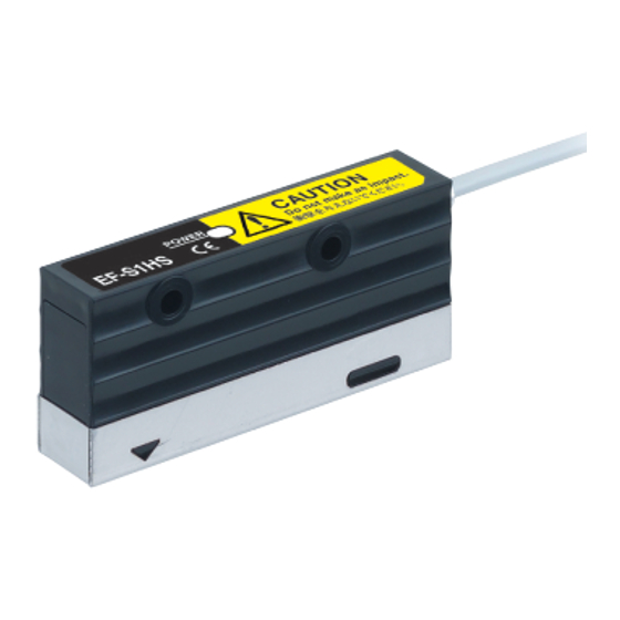
Electrostatic Sensor / Sensor Head
EF-S1HS
Thank you very much for using Panasonic products. Please read this Instruction
Manual carefully and thoroughly for the correct and optimum use of this product.
Kindly keep this manual in a convenient place for quick reference.
Never use this product with a device for personnel protection.
In case of using devices for personnel protection, use products
which meet laws or standards, such as OSHA, ANSI or IEC etc., for
WARNING
personnel protection applicable in each region or country.
1
OUTLINE
This product is a sensor head for connecting to a Electrostatic sensor controller
(EF-S1C).
It can be used for in-line measurement of electrical potentials on object surfaces.
2
PART DESCRIPTION
Power indicator (Green) (Note)
Note:
If the power indicator is not illuminated, check that the cables are connected correctly.
3
MOUNTING
A protective seal is affixed to the measuring part of
this product at the factory setting. Be sure to remove
this protective seal before use.
Do not let any dust or other foreign materials get
onto the sensor. If dust or other foreign materials get
onto the measuring part or the area around it, it may
interfere with correct measurement. If dust or other
foreign materials get onto the sensor, clean it off
with an air blower or similar.
Use M3 pan-head screws, spring washers and plain
washers (please arrange separately) to mount the
sensor so that it faces downward. The tightening
torque at this time should be 0.5N . m or less.
Example of recommended mounting
If a mounting bracket used by
the customer is brought close to
the measuring part, it may affect
measuring performance.
Mount the mounting bracket to
the sensor head so that it is as
far away from the measuring
part as possible.
If a charge builds up in the mounting bracket, it will affect measuring performance,
so be sure to ground the mounting bracket when using the sensor. However, the
metal enclosure should be insulated.
Mount in a location which is not subject to vibration.
Mount the sensor head so that the sensor is parallel to the object being measured,
and use the exclusive controller (EF-S1C) to set the measuring distance so that it
is equal to the distance from the sensor to the object being measured.
(Measurement accuracy will be better if the measurement distance is set to as
short a distance as possible.) For details on the setting method for the controller,
refer to the separate instruction manual for the exclusive controller (EF-S1C).
Range for measurement distance
Range for
measurement
0
distance
8
A
A
8 to 20.5mm
21
B
21 to 100mm
B
100
Ramco National
INSTRUCTION MANUAL
CMJE-EFS1HS No.0032-56V
Measuring part
Protective
seal
Plain washer
Please
arrange
Spring washer
separately.
M3 pan-head screw
Mounting
bracket
Measuring part
Measurement
Exclusive controller display
range
1kV
to
to
2kV
800-280-6933 | nsales@ramcoi.com
This product measures electric fields. Because of this, if any objects are present
inside the measurement area (refer to the illustration below) or near the sensor
head which might disturb the electric field around the object being measured, it
will affect measurement accuracy.
(
The shorter the measurement distance, the more difficult it will be for nearby
objects to have an adverse effect on measurement.
In order to obtain the most accurate measurement results, mount the sensor head
while taking into account factors such as the measurement distance,
measurement area and ambient environment.
In addition, after mounting the sensor head, carry out 0-Adjust and calibration
using the controller. For details, refer to the separate instruction manual for the
exclusive controller (EF-S1C).
Measurement distance - Measurement area (typical)
8
10
20
40
Measurement area (mm)
If several sensors are being used together, measurement errors will occur
because the metallic parts of the sensor heads will act as nearby metallic objects
that can affect measurement.
Mount the sensors so that there is a gap between them that is equal to or greater
than the values given in the table below.
L (mm)
D (mm)
8
0
8 to 12
8
12 to 16
18
L
16 to 30
51
(
)
Measurement
30 to 40
68
distance
4
CONNECTION TO EXCLUSIVE CONTROLLER(EF-S1C)
Be sure to turn off the power before connecting the sensor head and the exclusive
controller.
How to mount the sensor head to the controller
Insert the sensor head connector into the inlet of
the exclusive controller until it clicks.
Fit the connector cover on the connector.
When removing the sensor head, be sure to push
down the connector lock lever while removing it. If
the connector is pulled with excessive force (0.4N
or more) without the lock lever being pushed
down, it may damage the connector.
5
CONNECTION METHOD
The cable can be shortened to the desired length.
<Names of controller connector parts>
Power cable inlet
Strip gauge
Release procedure
Use a flathead screwdriver (with a blade width of 2mm or less) to
push in the operating lever (white) of the power cable inlet, and
remove the power cable.
Blade width
2mm or less
23
30
112
200
D
Controller
connector
Connector cover
Lock lever
Power cable inlet
Operating lever (white)
Release hole
Operating lever
(white)
www.panasonicsensors.com
Connection
Using the
strip the
)
bare leng
bared en
sure that
Use a flat
width of
operating
panel to t
Insert the
cable inle
Check th
cable is i
inlet as
right, and
section p
Termin
Place th
screwdriv
and again
lever (wh
the flathe
When a
lever (wh
cable will
Gently pu
that it do
6
MAJ
Item
Applicable con
Measurement
(measurement
Ambient temp
Ambient hum
Vibration resis
Shock resistan
Material
Cable
Weight
Notes: 1)
For d
for th
2)
This
the e
3)
This
to th
4)
If thi
hum
envir
Advertisement

Related Manuals for Panasonic EF-S1HS


Summary of Contents for Panasonic EF-S1HS
- Page 1 Use a flat exclusive controller (EF-S1C). width of Thank you very much for using Panasonic products. Please read this Instruction operating Manual carefully and thoroughly for the correct and optimum use of this product. Measurement distance - Measurement area (typical) panel to t Kindly keep this manual in a convenient place for quick reference.
- Page 2 Overseas Sales Division (Head Office) 2431-1 Ushiyama-cho, Kasugai-shi, Aichi, 486-0901, Japan Phone: +81-568-33-7861 FAX: +81-568-33-8591 About our sale network, please visit our website. PRINTED IN JAPAN © Panasonic Industrial Devices SUNX Co., Ltd. 2012 Ramco National 800-280-6933 | nsales@ramcoi.com www.panasonicsensors.com...